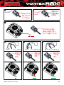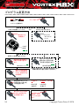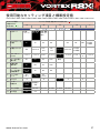
1
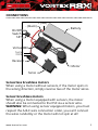
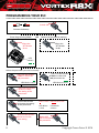
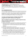
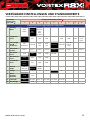
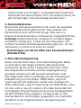
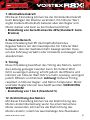
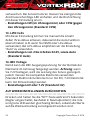
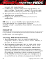
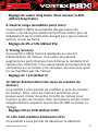
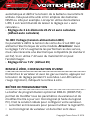
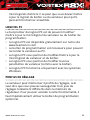
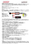
INSTRUCTION MANUAL
MODE D’EMPLOI
BEDIENUNGSANLEITUNG
INSTRUCTION MANUAL · ENGLISH
Warnings............................................................................... 3
Warranty............................................................................... 4
Connections.......................................................................... 5
ESC Calibration..................................................................... 6
Programming your ESC........................................................ 8
Available Parameters and default settings...................... 9
Features.............................................................................. 10
Status LED Function........................................................... 10
Audio Warning Tones........................................................ 10
ESC Parameters Setup....................................................... 11
Available Parameters........................................................ 12
1. Running Mode.................................................................. 12
2. Drag Brake Force.............................................................. 13
3. Low Voltage Cut-off.......................................................... 13
4. Start mode “punch”.......................................................... 14
5. Max Brake Force............................................................... 14
6. Max Reverse Force........................................................... 14
7. Initial Brake Force (minimum brake)............................. 14
8. Neutral Range................................................................... 15
9. Timing................................................................................ 15
12. Motor Rotation Direction.............................................. 15
13. LiPO Cells........................................................................ 15
14. BEC Voltage..................................................................... 16
Restore Default Settings................................................... 16
Program Box....................................................................... 16
PC Software........................................................................ 17
Setting Profiles................................................................... 17
2
Copyright Team Orion © 2014
WARNINGS
• Do not let children use this product without the
supervision of an adult.
• Never leave the ESC unsupervised while it is powered on.
• The ESC might get hot during use, be careful when
handling it.
• Always disconnect the battery after use, do not store with
the battery connected.
• Do not use near flammable materials.
• If the ESC has suspicious reactions, immediately
disconnect the battery and discontinue use.
www.teamorion.com3
WARRANTY
Team Orion guarantees this product to be free from
manufacturing and workmanship defects. The warranty
does not cover incorrect installation, components worn by
use, or any other problem resulting from incorrect use or
handling of the product. No liability will be accepted for any
damage resulting from the use of this product. By the act of
connecting and operating this product, the user accepts all
resulting liability. Is considered incorrect use:
• Failure to follow instructions.
• Improper use of the product (abusive use, out of spec,
etc.)
• Failure to adapt settings for proper function (improper
connections, wrong gearing, installation, setup, etc.).
• Overload, overheating (desoldering, melting, etc.).
• Running in inadequate conditions (damage or rust from
rain, humidity, etc.).
• Improper maintenance (presence of dirt, etc.).
• Disassembly, modification by the user (modifying original
connectors, wires, components, etc.).
• Mechanical damage due to external causes.
4
Copyright Team Orion © 2014
CONNECTIONS
On/Off
Switch
SET
- (black)
+ (red)
Battery
Vortex R8X
TH/CH2
ST/CH1
Receiver
Motor
Servo
Sensorless brushless motors
When using a motor without sensors, if the motor spins in
the wrong direction, simply reverse two of the motor wires.
Sensor brushless motors
When using a motor equipped with sensors, the motor
should also be connected to the ESC via a sensor wire.
WARNING! When using sensor equipped motors, you must
respect the A-B-C wire connection order, you can’t connect
the wires randomly or the motor will not spin at all!
www.teamorion.com5
ESC CALIBRATION
In order to ensure proper function, the ESC must be
calibrated to your transmitter inputs. Center the trims and
reset all settings inside the transmitter before proceeding to
the calibration
Calibration procedure
A.Make sure the ESC is switched off and then switch the
transmitter on.
B.Press and hold the setup button (located on the switch),
then switch on the ESC. Release the button as soon as the
red LED starts to flash.
C.Calibrate the throttle points by pressing the button once
after each step.
1. Neutral point (1 flash)
2. Full throttle (2 flashes)
3. Full brakes/reverse (3 flashes)
D.The motor will run 3 seconds after the last step is
completed.
6
Copyright Team Orion © 2014
1
2
ON/OFF
Press and
hold the
SET button
Keep
pressing
the SET
button
Switch ON
3
Release as
soon as soon as
the red LED
starts to blink
LED
4
5
Press
once
LED
6
Press
once
LED
Press
once
LED
www.teamorion.com7
PROGRAMMING YOUR ESC
1
Switch ON
Connect the battery
Enter Programming Mode
Reset to factory default settings
OR
2
2
Press the
SET button
for 1s
Press the
SET button
for 5s
LED
blinks
Select the parameter you wish to modify
3
3
Press the SET button
1 time to select the
1st parameter...
...press the SET button
2 times to select the
2nd parameter etc.
LED blinks 1 time
4
5
6
8
3
LED blinks 2 times
Press the SET button
for 3s to modify
the setting of the
parameter
Use the SET button
to change the setting
of the parameter.
Press the SET button
for 3s to save the
new setting
Press 1 time Press 2 times etc.
LED blinks
1 time
LED blinks
2 times
7
Switch OFF
ESC to complete
the procedure
Copyright Team Orion © 2014
AVAILABLE PARAMETERS AND DEFAULT SETTINGS
Parameter
(indicated by
green LED
)
Setting (indicated by red LED
1
2
3
4
5
)
6
7
8
9
25%
30%
100%
User set
in 1%
steps
3.2V/Cell
3.4V/Cell
User set
in 0.1V
steps
Level 4
Level 5
Level 6
Level 7
Level
8
Level 9
100%
Disable
7
8
Standard Parameters (adjustable with on/off switch)
1
Running
Mode
2
Drag Brake
Force
3
Forward
with
Brake
Forward/
Reverse
with
Brake
Foward/
Reverse
(For
Rock
Crawler)
0%
5%
10%
20%
Low Voltage
Cut-Off
Threshold
No
Protection
2.6V/Cell
2.8V/
Cell
3.0V/
Cell
4
Start Mode
(Punch)
Level 1
Level 2
Level 3
5
Max Brake
Force
25%
50%
75%
6
Max Reverse
Force
7
Initial Brake
Force
8
Neutral
Range
25%
50%
75%
100%
Drag
Brake
Force
0%
20%
40%
6%
(Narrow)
9%
(Normal)
12%
(Wide)
3
4
5
6
3S 11.1V
4S 14.8V
5S 18.5V
6S 22.2V
9
Timing
1
2
12
Motor
Rotation
Direction
CCW
CW
13
LiPO Cells
Auto
2S 7.4V
14
BEC Voltage
6V
7.2V
www.teamorion.com9
Thank you for purchasing a Team Orion Brushless ESC.
This ESC features the latest brushless technologies. Our
World Championship winning development team has
spent countless hours developing this ESC so that you
can experience ultimate performance. Please read these
instructions thoroughly before using the ESC.
FEATURES
•
•
•
•
•
•
Designed for on-road and off-road 1/8 scale cars
6V or 7.2V adjustable BEC for more servo performance
Works with sensor and sensorless motors
New case design with improved cooling system
Highly customizable software
Easy set-up via the setup button or optional digital
program box
STATUS LED FUNCTION
• When you switch on the ESC, the green LED flashes
according to the number of cells of the battery (4 cells = 4
flashes / 4 beep tones).
• In the neutral position, no LED are lit
• The red LED lights when the car is moving forward,
backwards or is braking.
AUDIO WARNING TONES
1. Input voltage: as it is switched on the ESC checks the
input voltage and emits a number of beep tones according
to the number of battery cells detected (4 cells = 4 beep
tones). If an issue is detected, the ESC emits two beep tones
10
Copyright Team Orion © 2014
repeatedly with a 1 second pause (xx-xx-xx).
2. Radio signal issue: as it is switched on and the ESC
checks the radio signal input. If an issue is detected, the
ESC emits one beep tone repeatedly with a 2 second pause
(x-x-x).
ESC PARAMETERS SETUP
You can adjust several parameters by using the setup button
located on the switch or by using the optional program box
(ORI65153). The green flashing LED indicates the parameter
and the red flashing LED indicates the setting value.
To setup custom parameter settings the optional
program box and PC software are required.
How to modify the parameters settings using the setup
button located on the switch.
A.Switch on the ESC.
B.Press and hold the setup button until the green LED starts
flashing and then release the setup button (holding the
setup button for 5 seconds will restore the ESC to factory
defaults).
C.Press the setup button once more.
D.The green LED starts flashing repeatedly, indicating the
currently selected parameter. One flash = parameter 1,
two flashes = parameter 2 and so on. Press the button to
switch between the different available parameters.
E. To change the setting of the actual parameter, press and
hold the setup button until the LED starts flashing red.
F. The red LED flashes indicating the actual setting. One
www.teamorion.com11
flash = setting 1, two flashes = setting 2 and so on. Press
the button to switch between the different available
settings.
G.Press and hold the setup button for 3 seconds to save the
modification.
H.Switch the ESC off and back on to make the parameter
change effective.
Note: you can only change one setting at a time, after each
modification you need to switch the ESC off and back on to
make the parameter change effective and be able to modify
another parameter.
AVAILABLE PARAMETERS
1. Running Mode
1. “Forward Only with Brake” this mode is meant for
competition use. In this mode the car can go forward and
brake, there is no reverse.
2. “Forward/Reverse with Brake” this is the basic all-around
mode. In this mode the car can go forward and reverse
and can also brake. When you move the throttle to the
reverse position while the car is moving forward, brakes
are applied until the car stops, reverse cannot engage
while the car is moving. To engage reverse, once the car
has stopped, release the brakes and move the throttle to
the reverse position again. While braking or in reverse, if
the throttle is moved to the forward position, the car will
immediately accelerate forward.
3. “Forward/Reverse” this mode is meant for Rock Crawler
use. In this mode there is no brake, the car can go from
12
Copyright Team Orion © 2014
forward to reverse immediately without any pause. Do
not use this mode with other car types as it can overload
and/or damage the ESC.
2. Drag Brake Force
Sets the amount of brake automatically applied when the
throttle is returned to the neutral position. This simulates
the engine breaking effect of a real car. Warning! Stronger
brakes will also result in higher ESC and motor running
temperature. Check the motor and ESC temperature and
adjust the parameter to keep temperature within safe limits.
›› Setting value from 0% to 100% or custom setting
(default 0%)
3. Low Voltage Cut-off
This function helps to prevent battery over-discharge. The
ESC continuously monitors the battery’s voltage. If the
voltage becomes lower than the threshold for 2 seconds,
the output power is shut off and the red LED flashes twice
repeatedly. The cutoff threshold calculation is based on LiPo
individual cell voltage. For NiMH batteries, if the voltage
battery pack is higher than 9.0V, it will be considered as
a 3 cell LiPo battery pack; if it is lower than 9.0V, it will be
considered as a 2 cell LiPo battery pack. Using the optional
Digital Program box you can adjust custom values for the
cutoff threshold. Unlike the preset values, custom cutoff
values are for the total battery voltage not individual cell
voltage.
›› Setting value from OFF to 3.4V/cell or custom value for
whole battery voltage (default 3.2V/cell)
www.teamorion.com13
4. Start mode “punch”
This parameter sets the initial throttle punch when the car
accelerates. Level 1 gives a very soft initial acceleration and
level 9 gives a very strong initial acceleration. Warning!
Stronger acceleration will also result in higher ESC and
motor running temperature. Check the motor and ESC
temperature and adjust the parameter to keep temperature
within safe limits.
›› Setting value from 1 to 9 (default 5)
5. Max Brake Force
This parameter adjusts the maximum breaking force. A
higher value provides stronger braking, but it also causes
extra stress to the ESC and motor. Warning! Stronger
brakes will also result in higher ESC and motor running
temperature. Check the motor and ESC temperature and
adjust the parameter to keep temperature within safe limits.
›› Setting value from disabled to 100% (default 50%)
6. Max Reverse Force
This parameter adjusts the maximum power when travelling
in reverse.
›› Setting value from 25% to 100% (default 25%)
7. Initial Brake Force (minimum brake)
This parameter adjusts the minimum amount of braking
power when the brakes engage. A higher value will give
stronger brakes but can also cause loss of control and extra
stress on the motor/ESC.
›› Setting value from drag brake value to 40% (default
drag brake)
14
Copyright Team Orion © 2014
8. Neutral Range
This parameter adjusts the throttle sensitivity around the
neutral point. A higher value means that the throttle will
have to be moved further for the car to move forward,
backward or brake.
›› Setting value from 6% to 12% (default 6%)
9. Timing
This parameter adjusts the motor drive current timing
allowing to increase performance. A lower value decreases
performance but increases efficiency and run time, a higher
value increase performance but lowers efficiency and run
time. Warning! Higher timing values cause the motor and/
or ESC to run hotter. If the motor and/or ESC overheat, they
can become damaged. USE WITH CAUTION!
›› Setting value from 1 to 8 (default 5)
12. Motor Rotation Direction
This parameter allows you to change the motor rotation
direction. Note: with sensorless motors you can also switch
two of the three motor wires to change the motor rotation
direction. With sensored motors you must respect the ABC
wire order and use this setting to change the motor rotation
direction.
›› Setting value CW or CCW (default CCW)
13. LiPO Cells
This parameter allows you to manually select the voltage of
the battery which is being used, overriding the automatic
detection (if you are using NiMH or LiFe batteries for
example). When using LiPo batteries It is recommended to
www.teamorion.com15
leave this setting on “auto calculate”.
›› Setting value from 2 to 6 cells 22.2V and auto-calculate
(default auto calculate)
14. BEC Voltage
This parameter sets the voltage output of the ESC BEC
system that powers the electronics on your car. WARNING!
Using 7.2V will increase the servo performance but requires
compatible electronics (regular electronics only work with
6V). Using 7.2V with 6V electronics can damage them.
›› Setting value 6V or 7.2V (default 6V)
RESTORE DEFAULT SETTINGS
With the ESC powered ON and the throttle in the neutral
position, press and hold the “SET” key for 5 seconds, the red
and green LED will flash simultaneously indicating that the
parameters have been reset to the factory default values.
PROGRAM BOX
The optional program box allows you to modify all of the ESC
parameters and to modify/update the ESC firmware (via the
PC software). It is the ideal way to adjust your ESC.
• The program box is required to use the ESC in conjunction
with the PC software.
• The program box firmware is independent from the ESC
firmware. You may need to update the program box or
ESC firmware via the PC software so that they can work
together.
16
Copyright Team Orion © 2014
PC SOFTWARE
The PC computer software is mainly used to update/modify
the ESC or program box firmware.
• You can download the PC software for free from our
website www.teamorion.com/R10-downloads.html
• The program box is required to connect your ESC to the
computer/PC software.
• The PC software allows you to update/modify your
program box and ESC firmware.
• The PC software allows you to modify all of the ESC
settings (as with the program box).
• The PC software currently only works with the Windows
operating system.
SETTING PROFILES
The ESC can store 3 different setting profiles, which means
that you can have three sets of different settings stored
inside the ESC’s memory. To be able to access this function,
you need to use the optional program box.
www.teamorion.com17
BEDIENUNGSANLEITUNG · DEUTSCH
Warnungen......................................................................... 19
Garantie.............................................................................. 20
Anschlüsse.......................................................................... 21
Regler-Kalibrierung............................................................ 22
Regler programmieren...................................................... 24
Verfügbare Einstellungen und Standardwerte.............. 25
Eigenschaften..................................................................... 26
Funktion der Status-LED................................................... 26
Warntöne............................................................................ 26
Regler-Einstellungen......................................................... 27
VERFÜGBARE Einstellungen.............................................. 28
1. Betriebsmodus / “Blinky” Modus.................................... 28
2. Automatik-Bremse........................................................... 29
3. Akku-Abschaltspannung.................................................. 29
4. Startmodus “Punch”......................................................... 30
5. Maximale Bremskraft...................................................... 30
6. Maximale Rückwärts-Leistung........................................ 30
7. Minimalbremskraft.......................................................... 31
8. Neutral-Bereich................................................................ 31
9. Timing................................................................................ 31
12. Drehrichtung des Motors.............................................. 31
13. LiPO Cells........................................................................ 32
14. BEC Voltage..................................................................... 32
Auf Werkseinstellungen zurücksetzen........................... 32
Programmierbox................................................................ 33
PC-Software........................................................................ 33
Einstellungsprofile............................................................. 33
18
Copyright Team Orion © 2014
WARNUNGEN
• Lassen Sie Kinder beim Gebrauch dieses Produkts nie
unbeaufsichtigt.
• Lassen Sie den Regler nie unbeaufsichtigt, während er
eingeschaltet ist.
• Der Regler kann während des Gebrauchs warm werden.
Seien Sie vorsichtig!
• Stecken Sie den Akku nach dem Gebrauch IMMER aus!
• Verwenden Sie den Regler nicht im Bereich von
brennbaren Materialien.
• Wenn der Regler auffällige Reaktionen zeigt, ziehen Sie
den Akku sofort aus und suchen im Fachhandel Hilfe.
www.teamorion.com19
GARANTIE
Team Orion garantiert, dass dieses Produkt frei ist von
Herstellungs- und Bearbeitungsfehlern. Die Garantie deckt
nicht inkorrekte Installation, Gebrauchsabnützung oder
jegliche andere Probleme, die durch inkorrekte Anwendung
des Produkts entstanden sind. Jegliche Haftung für Schäden,
die durch den Gebrauch dieses Produkts entstehen,
wird abgelehnt. Mit dem Gebrauch dieses Produkts
übernimmt der Anwender jegliche Haftung. Nicht korrekte
Anwendungen sind:
• Nicht befolgen der Anleitung.
• Nicht korrekter Gebrauch des Produkts (Missbrauch,
Überlastung etc)
• Falsche Einstellungen für korrekte Funktion (falscher
Anschluss, falsche Übersetzung, Installation etc.)
• Überlastung, Überhitzung (schmelzen, ablöten etc)
• Anwendung bei nicht adäquaten Bedingungen
(Beschädigung oder Rost durch Schmutz, Feuchtigkeit etc.)
• Falsche Pflege (Anwesenheit von Schmutz etc.)
• Demontage/Modifikation des Produkts durch den
Anwender (Ändern der Originalstecker, Kabel,
Komponenten etc.)
• Mechanische Beschädigung von aussen
20
Copyright Team Orion © 2014
ANSCHLÜSSE
- (schwarz)
EIN/AUS
Schalter
SET
+ (rot)
Akku
Vortex R10.1 Pro
TH/CH2
ST/CH1
Empfänger
Motor
Servo
Sensorless Brushless Motoren: Wenn Sie einen Motor
ohne Sensoren verwenden und dieser nach dem Anschluss
in die falsche Richtung dreht, vertauschen Sie zwei beliebige
Anschlusskabel des Motors.
Sensor Brushless Motoren: Wenn Sie einen Sensor
Brushless Motor verwenden, müssen Sie ihn zusätzlich mit
einem Sensor-Kabel an den Regler anschliessen. ACHTUNG!
Wenn Sie einen Motor mit Sensoren verwenden, müssen Sie
die Reihenfolge A-B-C der Motorkabel beachten. Wenn Sie
diese Reihenfolge nicht beachten, dreht der Motor nicht.
www.teamorion.com21
REGLER-KALIBRIERUNG
Um die korrekte Funktion des Reglers zu gewährleisten,
muss er auf Ihre Fernsteuerung abgestimmt werden.
Zentrieren Sie hierzu alle Trimmer und setzen Sie alle
Einstellungen am Sender zurück, bevor Sie mit der
Kalibrierung des Reglers beginnen.
Befolgen Sie diese Schritte, um den Regler zu kalibrieren
A.Schalten Sie den Regler aus und die Fernsteuerung ein.
B.Drücken und halten Sie die “SET”-Taste (auf dem Ein-/AusSchalter) und schalten Sie den Regler ein. Lassen Sie die
“SET”-Taste los, sobald die LED rot blinkt.
C.Stellen Sie die folgenden Positionen am Sender ein und
bestätigen Sie jeweils mit der “SET”-Taste:
1. Neutralpunkt (LED blinkt 1 mal)
2. Vollgas (LED blinkt 2 mal)
3. Vollbremse/rückwärts (LED blinkt 3 mal)
D.Der Motor dreht nach dem letzten Schritt während 3
Sekunden. Danach ist der Vorgang abgeschlossen.
22
Copyright Team Orion © 2014
1
2
EIN/AUS
SET Taste
drücken
und halten
SET Taste
stetig
halten
Einschalten
3
Loslassen, sobald
die rote LED blinkt
LED
4
5
1 mal
drücken
LED
6
1 mal
drücken
LED
1 mal
drücken
LED
www.teamorion.com23
REGLER PROGRAMMIEREN
1
Einschalten
Akku einstecken
Programmiermodus starten
Alle Einstellungen zurücksetzen
OR
2
2
SET Taste
während
5s drücken
SET Taste
während
1s drücken
LED
blinkt
3
4
5
6
24
Wählen Sie den Parameter, den Sie ändern möchten
3
...drücken Sie die SET
Drücken Sie die SET
Taste 2 mal, um den
Taste 1 mal, um den
ersten Parameter zu
zweitenParameter zu
wählen...
wählen...
LED blinkt 1 mal
LED blinkt 2 mal
3
Drücken Sie die SET
Taste während 3s,
um den Parameter
zu ändern.
Ändern Sie die
Einstellung mit der
SET Taste.
SET Taste während
3s drücken, um die
Einstellung zu
speichern.
1 mal drücken 2 mal drücken etc.
LED blinkt
1 mal
LED blinkt
2 mal
7
Regler ausschalten, um
den Vorgang
abzuschliessen
Copyright Team Orion © 2014
VERFÜGBARE EINSTELLUNGEN UND STANDARDWERTE
Parameter
(indicated by
green LED
)
Setting (indicated by red LED
1
2
3
4
5
)
6
7
8
9
25%
30%
100%
User set
in 1%
steps
3.2V/Cell
3.4V/Cell
User set
in 0.1V
steps
Level 4
Level 5
Level 6
Level 7
Level
8
Level 9
100%
Disable
7
8
Standard Parameters (adjustable with on/off switch)
1
Running
Mode
2
Drag Brake
Force
3
Forward
with
Brake
Forward/
Reverse
with
Brake
Foward/
Reverse
(For
Rock
Crawler)
0%
5%
10%
20%
Low Voltage
Cut-Off
Threshold
No
Protection
2.6V/Cell
2.8V/
Cell
3.0V/
Cell
4
Start Mode
(Punch)
Level 1
Level 2
Level 3
5
Max Brake
Force
25%
50%
75%
6
Max Reverse
Force
7
Initial Brake
Force
8
Neutral
Range
25%
50%
75%
100%
Drag
Brake
Force
0%
20%
40%
6%
(Narrow)
9%
(Normal)
12%
(Wide)
3
4
5
6
3S 11.1V
4S 14.8V
5S 18.5V
6S 22.2V
9
Timing
1
2
12
Motor
Rotation
Direction
CCW
CW
13
LiPO Cells
Auto
2S 7.4V
14
BEC Voltage
6V
7.2V
www.teamorion.com25
Vielen Dank für den Kauf eines Team Orion Brushless
Fahrtenreglers. Dieser Fahrtenregler ist mit der aktuellsten
Technologie ausgerüstet. Unser Team, das mit zahlreichen
Weltmeistertiteln ausgezeichnet worden ist, hat unzählige
Teststunden in den Regler investiert, um die höchstmögliche
Leistung zu erzielen. Lesen Sie diese Anleitung genau durch,
bevor Sie den Regler verwenden.
EIGENSCHAFTEN
•
•
•
•
•
•
Entwickelt für On-Road und Off-Road 1/8er Fahrzeuge
6V oder 7.2V BEC für bessere Servo-Leistung
Für Sensor und Sensorless Motoren
Neues Gehäuse Design mit verbesserter Kühlung
Neue, optimierte Software mit zahlreichen Einstellungen
Einfache Einstellung mit der Setup-Taste oder
Programmierbox
FUNKTION DER STATUS-LED
• Wenn Sie den Regler einschalten, blinkt die LED grün
• In Neutralposition leuchtet keine LED
• Die rote LED leuchtet, wenn das Fahrzeug vorwärts oder
rückwärts fährt oder bremst
WARNTÖNE
Problem mit Eingangsspannung: Der Regler prüft die
Eingangsspannung, sobald er eingeschaltet wird. Wenn ein
Problem erkannt wird, ertönen wiederholt zwei Signaltöne
im Abstand von 1 Sekunde (xx-xx-xx).
Problem mit dem Empfangssignal: Der Regler prüft das
26
Copyright Team Orion © 2014
Empfangssignal, sobald er eingeschaltet ist. Falls ein
Problem besteht, ertönt wiederholt ein Signalton im Abstand
von 2 Sekunden (x-x-x).
REGLER-EINSTELLUNGEN
Sie können Einstellungen mit Hilfe der Setup Taste auf dem
Ein-/Aus-Schalter oder mit der optionalen Programmierbox
vornehmen (ORI65153). Die grüne LED zeigt den gewählten
Parameter und die rote LED den Wert des Parameters.
Benutzerspezifische Werte können nur mit Hilfe der
optionalen Programmierbox vorgenommen werden.
Standard-Einstellungen ändern mit Hilfe der Setup Taste
auf dem Ein-/Aus-Schalter
1. Schalten Sie den Regler ein
2. Drücken und halten Sie die Setup-Taste, bis die grüne LED
zu blinken beginnt. Danach lassen Sie die Taste los (bei
Halten der “SET” -Taste während 5 Sekunden wird der
Regler auf die Standardeinstellungen zurückgesetzt)
3. Drücken Sie die Setup-Taste noch einmal.
4. Die grüne LED blinkt wiederholt 1 mal. Dies zeigt an, dass
die Einstellung 1 gewählt ist.
5. Um den aktuellen Parameter zu ändern, drücken Sie die
Setup -Taste bis die LED rot blinkt.
6. Die rote LED wird nun den Wert der Einstellung anzeigen:
blinkt sie 1 mal, so beträgt der Wert 1, blinkt sie 2 mal,
beträgt der Wert 2 usw. Drücken Sie die Setup -Taste, um
den Wert zu verändern.
7. Wenn Sie den gewünschten Wert eingestellt haben,
www.teamorion.com27
drücken und halten Sie die Setup -Taste während 3
Sekunden, um die Änderung zu speichern.
8. Schalten Sie den Regler aus und wieder ein, um die neue
Einstellung zu aktivieren.
Bitte beachten: Sie können jeweils nur eine Einstellung
verändern. Nach jeder Veränderung muss der Regler einund ausgeschaltet werden.
VERFÜGBARE EINSTELLUNGEN
1. Betriebsmodus / “Blinky” Modus
1. “Vorwärs mit Bremse” Dieser Modus ist für den
Renneinsatz entwickelt worden. Er weist eine
Vorwärts- und eine Bremsfunktion auf, jedoch keinen
Rückwärtsgang.
2. “Vorwärts/Rückwärts mit Bremse” ist der Modus für den
Allround-Einsatz. Ihr Fahrzeug kann damit vorwärts und
rückwärts fahren. Wenn Sie den Gashebel während der
Vorwärtsfahrt auf Rückwärtsposition stellen, bremst das
Fahrzeug bis zum Stillstand. Es ist nicht möglich, den
Motor rückwärts drehen zu lassen, bevor das Fahrzeug
zum Stillstand gekommen ist. Wenn Sie rückwärts fahren
wollen, müssen Sie den Gashebel nach der Vollbremsung
wieder auf die Neutralposition bewegen, bevor Sie ihn zur
Rückwärtsfahrt wieder auf Rückwärtsposition bringen.
Wenn Sie bremsen oder rückwärts fahren und danach
in eine Vorwärtsposition übergehen, fährt das Fahrzeug
umgehend vorwärts
3. “Vorwärts/Rückwärts” ist für Rock Crawler geeignet.
Dieser Modus hat keine Bremse. Das Fahrzeug kann
28
Copyright Team Orion © 2014
zudem direkt von Vorwärts- zu Rückwärtsfahrt wechseln.
Verwenden Sie diesen Modus nicht mit anderen Autos, da
der Fahrtenregler sonst beschädigt werden kann.
2. Automatik-Bremse
Bremst das Fahrzeug automatisch ab, wenn der Gashebel
in die Neutralposition geführt wird. Dies simuliert die
Motorbremse eines echten Fahrzeugs. Dies kann zu
besserem Einlenkverhalten und besseren Fahrgefühl führen.
Achtung! Stärkere Bremsen resultieren in höherer Reglerund Motor-Temperatur. Prüfen Sie die Temperatur und
nehmen Sie kleine Einstellungsveränderungen vor, um die
Temperatur in sicheren Grenzen zu halten.
›› Einstellungen von 0% bis 100% oder benutzerfefiniert
(Standard: 0%).
3. Akku-Abschaltspannung
Diese Funktion dient dazu, eine Tiefentladung des Akkus
zu verhindern. Der Regler prüft die Akku-Spannung
fortlaufend. Wenn sie für 2 Sekunden oder mehr unter
das eingestellte Limit fällt, wird die Ausgangsleistung
gestoppt und die rote LED leuchtet wiederholt 2 mal.
Das eingestellte Limit ist abhängig von der individuellen
Zellspannung von LiPo-Akkus. NiMH Akkus, die mehr
Spannung als 9.0V aufweisen, werden wie 3-zellige LiPoAkkus behandelt. Liegt die Spannung von NiMH Akkus unter
9.0 Volt, wird er wie ein 2-Zellen LiPo-Akku behandelt. Mit
der Digitalen Programmierbox können Sie beliebige Werte
als Abschaltspannung eingeben. Im Gegensatz zu den
Standardwerten, die im Regler gespeichert sind, betreffen
die Werte in der Programmierbox die Spannung des
www.teamorion.com29
gesamten Akkus und nicht der einzelnen Zellen.
›› Von OFF bis 3.4V/Zelle oder benutzerdefiniert für den
kompletten Akku (Standard: 3.2V/Zelle).
4. Startmodus “Punch”
Diese Einstellung ermöglicht es, die
Beschleunigungscharakteristik des Fahrzeugs zu verändern.
Level 1 ergibt eine sehr feine Beschleunigung und Level
9 beschleunigt sehr stark aus dem Stand. Achtung!
Stärkerer Punch resultiert in höherer Regler- und MotorTemperatur. Prüfen Sie die Temperatur und nehmen Sie
kleine Einstellungsveränderungen vor, um die Temperatur in
sicheren Grenzen zu halten.
›› Einstellungen von 1 bis 9 (Standard: 5).
5. Maximale Bremskraft
Diese Einstellung betrifft die maximale Bremskraft des
Reglers. Ein höherer Wert führt zu stärkerer Bremskraft.
Zu starke Bremskraft kann zum Blockieren der Räder und
Kontrollverlust über das Fahrzeug führen.
Achtung! Stärkere Bremsen resultieren in höherer Reglerund Motor-Temperatur. Prüfen Sie die Temperatur und
nehmen Sie kleine Einstellungsveränderungen vor, um die
Temperatur in sicheren Grenzen zu halten.
›› Einstellungen von deaktiviert bis 100% (Standard:
50%).
6. Maximale Rückwärts-Leistung
Diese Einstellung stellt die maximale Leistung für die
Rückwärtsfahrt ein.
›› Einstellungen von 25% bis 100% (Standard: 25%)
30
Copyright Team Orion © 2014
7. Minimalbremskraft
Mit dieser Einstellung können Sie die minimale Bremskraft
beim Betätigen der Bremse verändern. Ein höherer Wert
ergibt stärkere Bremskraft, belastet aber den Regler und
Motor stärker und kann zu Kontrollverlust führen.
›› Einstellung von Auto-Bremse bis 40% (Standard: AutoBremse)
8. Neutral-Bereich
Diese Einstellung betrifft die Empfindlichkeit des
Regelverhaltens um den Neutralpunkt. Ein höherer Wert
bedeutet, dass der Gashebel mehr bewegt werden muss,
um das Fahrzeug vorwärts oder rückwärts zu bewegen oder
abzubremsen.
9. Timing
Diese Einstellung beeinflust das Timing des Motors, womit
die Leistung gesteigert werden kann. Ein tieferer Wert
führt zu weniger Leistung, erhöht jedoch die Effizienz und
Fahrzeit; ein höherer Wert führt zu mehr Leistung, verringert
jedoch Effizienz und Fahrzeit. Achtung! Höheres Timing
resultiert in höherer Regler- und Motor-Temperatur. Motor
und/oder Regler können beschädift werden. VORSICHTIG
VERWENDEN!
›› Einstellung von 1 bis 8 (Standard: 5)
12. Drehrichtung des Motors
Mit dieser Einstellung können Sie die Drehrichtung des
Motors ändern.Bemerkung: wenn Sie einen Sensorless
Motor verwenden, können Sie die Drehrichtung des
Motors ändern, indem Sie zwei beliebige Anschlusskabel
www.teamorion.com31
vertauschen. Bei Sensormotoren müssen Sie zwingend die
Anschlussreihenfolge ABC einhalten und die Drehrichtung
mit dieser Einstellung änern.
›› Einstellungen CW (im Uhrzeigersinn) oder CCW (gegen
den Uhrzeigersinn (Standard: CCW)
13. LiPO Cells
Mit dieser Einstellung können Sie manuell die Anzahl
Zellen Ihres Akkus erfassen, dabei wird die Auto-Funktion
überschrieben (z.B. wenn Sie NiMH oder LiFe Akkus
verwenden). Bei LiPo Akkus empfehlen wir die Einstellung
“Auto” zu verwenden.
›› Einstellungen von 2 bis 6 Zellen 22.2V, sowie Auto
(Standard: Auto)
14. BEC Voltage
Damit kann die BEC Ausgangsspannung für der Betrieb der
Elektronik im Fahrzeug festgelegt werden. Achtung: wenn
Sie 7.2V festlegen, wird die Leistung des Servos gesteigert,
jedoch müssen Sie kompatible Elektronik verwenden
(Standard Elektronik funktioniert nur mit 6V). 7.2V Elektronik
kann mit 6V beschädigt werden.
›› Einstellungen 6V oder 7.2V (Standard: 6V)
AUF WERKSEINSTELLUNGEN ZURÜCKSETZEN
Drücken und halten Sie die “SET”-Taste während 5 Sekunden
(Regler eingeschaltet, Gashebel in Neutralposition): die rote
und grüne LED werden gleichzeitig blinken, sobald alle Werte
auf die Werkseinstellung zurückgesetzt worden sind.
32
Copyright Team Orion © 2014
PROGRAMMIERBOX
Die optionale Programmierbox erlaubt es, die Einstellungen
Ihres Reglers zu ändern, sowie die Firmware zu aktualisieren
(mit Hilfe der PC-Software).
• Die Programmierbox wird verwendet, um den Regler
zusammen mit der PC-Software zu verwenden.
• Die Firmware der Programmierbox ist unabhängig von
der Regler-Firmware. Je nach Regler muss die Firmware
der Programmierbox oder des Reglers mit Hilfe der
PC-Software aktualisiert werden, damit sie zusammen
funktionieren.
PC-SOFTWARE
Die PC-Software wird dazu verwendet, um die Firmware des
Reglers oder der Programmierbox zu aktualisieren.
• Die PC-Software kann auf www.teamorion.com/R10downloads.html heruntergeladen werden
• Die Programmierbox wird verwendet, um den Regler mit
dem Computer bzw. der PC-Software zu verbinden.
• Die PC-Software erlaubt Ihnen, die Firmware des Reglers
bzw. der Programmierbox zu ändern/aktualisieren.
• Mit der PC-Software können wie mit der Programmierbox
alle Einstellungen am Regler vorgenommen werden.
• Die PC-Software ist momentan ausschliesslich in einer
PC-Version verfügbar.
EINSTELLUNGSPROFILE
Der Regler kann 3 verschiedene Profile speichern. Hierzu
benötigen Sie die optionale Programmierbox.
www.teamorion.com33
MODE D‘EMPLOI · FRANCAIS
Mises en garde................................................................... 35
Garantie.............................................................................. 36
Branchements.................................................................... 37
Calibrage du variateur...................................................... 38
Programmation du variateur........................................... 40
Paramètres du variateur et réglages par défaut........... 41
Caractéristiques................................................................. 42
Fonctionnement des LED d’état....................................... 42
Signaux sonores................................................................. 42
Paramètrage du régulateur.............................................. 43
Paramètres......................................................................... 44
1. Running Mode (fonctionnement)................................... 44
2. Drag Brake (frein moteur)............................................... 45
3. Low voltage cut-off (protection tension batterie)........ 45
4. Start mode “punch” (puissance accélération)............... 46
5. Max brake force (frein max)............................................ 46
6. Max reverse force (puissance marche arrière)............. 46
7. Initial brake force (frein initial)....................................... 46
8. Neutral range (sensibilité point mort)........................... 47
9. Timing (avance)................................................................. 47
12. Motor Rotation Direction (sens de rotation du moteur)
47
13. LiPo Cells (nombre d’éléments LiPo)........................... 47
14. BEC Voltage (tension alimentation BEC)..................... 48
Remise à zéro, configuration d’usine.............................. 48
Boîtier de programmation................................................ 48
Logiciel PC........................................................................... 49
Profils de réglage............................................................... 49
34
Copyright Team Orion © 2014
MISES EN GARDE
• Ne laissez pas les enfants utiliser ce produit sans la
supervision d’un adulte.
• Ne laissez pas un régulateur enclenché sans surveillance.
• Le régulateur peut chauffer pendant l’utilisation, faites
attention lorsque vous le manipulez.
• Débranchez toujours la batterie après l’emploi. Ne stockez
pas le régulateur avec la batterie branchée.
• N’utilisez pas le régulateur à proximité de matières
inflammables.
• Si le régulateur réagit de façon suspecte, débranchez-le et
arrêtez immédiatement son utilisation.
www.teamorion.com35
GARANTIE
Team Orion garanti que ce produit ne comporte pas de
défauts de fabrication. Cette garantie n’est pas valable
lors d’une mauvaise utilisation, d’usure due à l’utilisation
ou tout autre problème résultant d’une utilisation ou
d’une manipulation inappropriée du produit. Aucune
responsabilité ne sera assumée pour un quelconque
dommage résultant de l’utilisation du produit. Du fait
de connecter et d’utiliser ce produit, l’utilisateur accepte
toutes les responsabilités découlant de son utilisation. Sont
considérés comme mauvaise utilisation:
• Ne pas suivre les instructions.
• Utilisation inadaptée (abus, utilisation extrême, etc.) :
• Réglages inadaptés (mauvaises connexions, rapport
inadapté, mauvaise installation, etc.).
• Surcharge, surchauffe (éléments dessoudés, brûlés, etc.).
• Conditions d’utilisation inappropriées (humidité, pluie,
etc.).
• Mauvais entretien (présence de saleté, etc.).
• Démontage, modifications par l’utilisateur (modification
des connecteurs, câbles, composants, etc.).
• Dommage dus aux chocs
36
Copyright Team Orion © 2014
BRANCHEMENTS
+ (rouge)
- (noir)
ON/OFF
Interrupteur
SET
Accu
Vortex R8X
TH/CH2
ST/CH1
Récepteur
Moteur
Servo
Moteur brushless sensorless
Lorsqu’un moteur sensorless est utilisé, si le moteur tourne
à l’envers, inversez deux des trois fils moteur pour modifier
le sens de rotation.
Moteur brushless avec sensor
Lorsque vous utilisez un moteur avec sensor, vous devez
en plus utiliser un câble sensor pour relier le moteur au
variateur. ATTENTION ! Lorsque vous utilisez un moteur
avec sensor, vous devez impérativement respecter l’ordre
des fils ABC du moteur, sinon le moteur ne fonctionnera pas
du tout !
www.teamorion.com37
CALIBRAGE DU VARIATEUR
Afin d’assurer un fonctionnement optimal, le variateur doit
être calibré par rapport au signal de l’émetteur. Avant de
procéder au calibrage, centrez le trim des gaz et désactivez
les fonctions spéciales qui pourraient être actives dans
l’émetteur.
Procédure de calibrage
A.Assurez-vous que le variateur est éteint puis allumez
l’émetteur.
B.Pressez sur le bouton de réglage situé sur l’interrupteur
tout en enclenchant le variateur. Relâchez le bouton dès
que la LED rouge clignote.
C.Calibrez le variateur en appuyant une fois sur le bouton à
chaque étape.
1. Neutre (1 flash)
2. Plein gaz (2 flashs)
3. Freins/marche arrière (3 flashs)
D.Le variateur est fonctionnel 3 secondes après que le
calibrage ait été effectué.
38
Copyright Team Orion © 2014
1
2
ON/OFF
Maintenir
pressé
Maintenir
pressé
Enclencher
3
Relâcher lorsque la
LED rouge clignote
LED
4
5
Pressez
une fois
LED
6
Pressez
une fois
LED
Pressez
une fois
LED
www.teamorion.com39
PROGRAMMATION DU VARIATEUR
1
Enclencher
Brancher la batterie
Mode de programmation
Remise en configuration d‘usine
OR
2
2
Pressez le
bouton
pendant 1sec
Pressez le
bouton
pendant 5sec
La LED
clignote
Sélectionnez le paramètre que vous voulez modifier
3
3
Pressez une fois pour
sélectionner le 1er
paramètre
La LED clignote 1 fois
4
5
6
40
Pressez deux fois pour
sélectionner le 2ème
paramètre
3
La LED clignote 2 fois
Pressez pendant
3sec pour modifier
le paramètre
Modifiez le réglage
en pressant le bouton
Pressez pendant 3
secondes pour
sauvegarder la
modification
1 pression
2 pressions
La LED
clignote
une fois
La LED
clignote
2 fois
etc.
7
Eteignez le
variateur pour
compléter la
procédure
Copyright Team Orion © 2014
PARAMÈTRES DU VARIATEUR ET RÉGLAGES PAR DÉFAUT
Parameter
(indicated by
green LED
)
Setting (indicated by red LED
1
2
3
4
5
)
6
7
8
9
25%
30%
100%
User set
in 1%
steps
3.2V/Cell
3.4V/Cell
User set
in 0.1V
steps
Level 4
Level 5
Level 6
Level 7
Level
8
Level 9
100%
Disable
7
8
Standard Parameters (adjustable with on/off switch)
1
Running
Mode
2
Drag Brake
Force
3
Forward
with
Brake
Forward/
Reverse
with
Brake
Foward/
Reverse
(For
Rock
Crawler)
0%
5%
10%
20%
Low Voltage
Cut-Off
Threshold
No
Protection
2.6V/Cell
2.8V/
Cell
3.0V/
Cell
4
Start Mode
(Punch)
Level 1
Level 2
Level 3
5
Max Brake
Force
25%
50%
75%
6
Max Reverse
Force
7
Initial Brake
Force
8
Neutral
Range
25%
50%
75%
100%
Drag
Brake
Force
0%
20%
40%
6%
(Narrow)
9%
(Normal)
12%
(Wide)
3
4
5
6
3S 11.1V
4S 14.8V
5S 18.5V
6S 22.2V
9
Timing
1
2
12
Motor
Rotation
Direction
CCW
CW
13
LiPO Cells
Auto
2S 7.4V
14
BEC Voltage
6V
7.2V
www.teamorion.com41
Nous vous félicitons pour l’achat d’un variateur brushless
Team Orion. Ce variateur est équipé des technologies les
plus récentes. Notre team champion du monde a passé
de longues heures à développer ce produit afin que vous
puissiez bénéficier des performances les plus élevées qui
soient. Veuillez lire attentivement ce mode d’emploi avant
d’utiliser le variateur.
CARACTÉRISTIQUES
• Conçu pour les voitures piste ou tout-terrain à l’échelle
1/8.
• BEC 6V ou 7.2V pour des servos plus performants
• Fonctionne avec les moteurs sensor ou sensorless
• Nouveau boîtier avec système de refroidissement
amélioré
• Software hautement paramétrable
• Paramétrage simple via un bouton ou boîtier de
programmation
FONCTIONNEMENT DES LED D’ÉTAT
• Lorsque vous enclenchez le variateur, la LED verte
clignote en rapport avec le nombre d’éléments de
la batterie connectée (4 éléments = 4 flash = 4 beep
sonores).
• Au neutre aucune LED ne s’allume.
• La LED rouge s’allume lorsque la voiture avance, recule
ou freine.
SIGNAUX SONORES
42
Copyright Team Orion © 2014
1. Problème d’alimentation: le variateur contrôle la tension
de la batterie lorsqu’il est enclenché. Si un problème est
détecté, le variateur émet deux signaux sonores avec 2
secondes de pause entre les répétitions (xx-xx-xx).
2. Problème de signal radio: le variateur contrôle le signal
radio lorsqu’il est enclenché. Si un problème est détecté, le
variateur émet un signal sonore avec 2 secondes de pause
entre les répétitions (x-x-x).
PARAMÈTRAGE DU RÉGULATEUR
Les paramètres du variateur peuvent être modifiés en
utilisant le bouton de réglage situé sur l’interrupteur ou en
utilisant le boîtier de programmation optionnel (ORI65153).
La LED verte indique le paramètre et la LED rouge indique la
valeur du réglage du paramètre.
Note : pour modifier les valeurs « custom » l’utilisation
du boîtier optionnel et du logiciel PC est obligatoire.
A.Enclenchez le variateur.
B.Pressez sur le bouton jusqu’à ce que la LED verte clignote
puis relâchez-le (si vous le maintenez pressé pendant 5
secondes, les paramètres sont remis en configuration
d’usine).
C.Pressez encore une fois sur le bouton.
D.La LED verte clignote à répétition, indiquant le paramètre
actuel. Un flash = paramètre 1, deux flash = paramètre 2
et ainsi de suite. Pressez sur le bouton pour passer d’un
paramètre à l’autre.
E. Pour modifier le paramètre, pressez sur le bouton jusqu’à
www.teamorion.com43
ce que la LED rouge clignote.
F. La LED rouge clignote, indiquant le réglage actuel. Un
flash = réglage 1, deux flash = réglage 2 et ainsi de suite.
Pressez sur le bouton pour passer d’un réglage à l’autre.
G. Appuyez sur le bouton pendant 3 secondes pour
sauvegarder la modification.
H.Eteignez puis rallumez le variateur pour valider la
modification.
NB : Vous ne pouvez modifier qu’un paramètre à la fois.
Pour sauvegarder une modification et pouvoir
modifier un autre paramètre, il faut éteindre et rallumer le
variateur.
PARAMÈTRES
Les paramètres standards peuvent être modifiés à l’aide du
bouton situé sur l’interrupteur.
1. Running Mode (fonctionnement)
1. “Marche avant avec frein” ce mode est destiné à la
compétition. Dans ce mode la voiture avance et freine, il
n’y a pas de marche arrière.
2. “Marche avant/arrière avec frein” ce mode est le mode
basique passe partout. Dans ce mode, la voiture peut
avancer, reculer et freiner. Lorsque vous tirez/poussez
le manche des gaz en position marche arrière pendant
que la voiture avance, le variateur freine la voiture jusqu’à
ce qu’elle soit totalement arrêtée. Une fois la voiture à
l’arrêt, relâchez le manche des gaz puis tirez/poussez le
en position marche arrière à nouveau pour enclencher
44
Copyright Team Orion © 2014
la marche arrière. Lorsque la voiture recule ou pendant
que vous freinez, si vous tirez/poussez le manche des
gaz en position marche avant, la voiture repart en avant
instantanément.
3. “Marche avant/arrière” ceci est le mode de
fonctionnement idéal pour les Rock Crawler. Dans ce
mode le variateur passe de la marche avant à la marche
arrière et inversement, sans délai. Attention n’utilisez pas
ce mode avec des autres types de voitures car cela peut
surcharger le variateur et l’endommager.
2. Drag Brake (frein moteur)
Ce paramètre règle la quantité de frein appliqué lorsque
les gaz sont au neutre. Cette fonction simule l’effet de frein
moteur d’une vraie voiture. Attention ! Une valeur élevée
provoque plus de contraintes sur le moteur et le variateur,
assurez-vous qu’ils ne surchauffent pas !
›› Réglage de 0% à 100% ou custom (défaut 0%)
3. Low voltage cut-off (protection tension batterie)
Le variateur contrôle constamment la tension de la batterie.
Si la tension passe en-dessous du seuil prédéfini pendant 2
secondes, le variateur coupe l’alimentation et la LED rouge
clignote deux fois à répétition. Le seuil de coupure est
calculé sur la base d’une batterie LiPo. Avec une batterie
NiMH, si sa tension est supérieure à 9V alors la coupure
sera basée sur celle d’un LiPo 3 éléments, en-dessous de
9V la coupure sera basée sur celle d’un LiPo 2 éléments. En
utilisant le boîtier de programmation vous pouvez définir
une valeur personnalisée, dans ce cas la valeur se réfère à
la tension de la batterie plutôt qu’à celle d’un seul élément.
www.teamorion.com45
Réglage de OFF à 3.4V/élément ou custom pour la tension
totale de la batterie (défaut 3.2V/élément)
4. Start mode “punch” (puissance accélération)
Ce paramètre défini la puissance de l’accélération. Le niveau
1 donne une accélération peu puissante et le niveau 9 donne
l’accélération la plus puissante. Attention ! Une valeur élevée
provoque plus de contraintes sur le moteur et le variateur,
assurez-vous qu’ils ne surchauffent pas !
›› Réglage de 1à 9 (défaut 5)
5. Max brake force (frein max)
Ce paramètre défini la puissance du freinage. Une valeur
plus élevée donne un freinage plus puissant mais crée aussi
plus de contraintes sur le variateur et le moteur. Attention
! Une valeur élevée provoque plus de contraintes sur le
moteur et le variateur, assurez-vous qu’ils ne surchauffent
pas !
›› Réglage de désactivé (disabled) à 100% (défaut 50%)
6. Max reverse force (puissance marche arrière)
Ce paramètre défini la puissance/vitesse maximale en
marche arrière.
›› Réglage de 25% à 100% (défaut 25%)
7. Initial brake force (frein initial)
Ce paramètre défini la puissance de freinage initiale lorsque
le frein est actionné. La valeur minimale est égale à la valeur
du frein moteur (s’il est activé). Attention ! Une valeur
élevée provoque plus de contraintes sur le moteur et le
variateur, assurez-vous qu’ils ne surchauffent pas !
46
Copyright Team Orion © 2014
›› Réglage de valeur drag brake (frein moteur) à 40%
(défaut drag brake)
8. Neutral range (sensibilité point mort)
Ce paramètre défini la sensibilité des gaz autour du
neutre. Une value plus élevée fait qu’il faut utiliser plus de
débattement de la commande des gaz pour que la voiture
avance, recule ou freine.
›› Réglage de 6% à 12% (défaut 9%)
9. Timing (avance)
Ce paramètre défini l’avance appliquée au courant
d’alimentation du moteur. Une valeur plus élevée
augmente les performances mais diminue le rendement et
l’autonomie. Attention ! Une valeur élevée provoque plus de
contraintes sur le moteur et le variateur, assurez-vous qu’ils
ne surchauffent pas !du moteur.
›› Réglage de 1 à 8 (défaut 5)
12. Motor Rotation Direction (sens de rotation du
moteur)
Ce paramètre vous permet de modifier le sens de rotation
du moteur. Note : avec les moteurs sensorless vous
pouvez aussi croiser deux des trois fils du moteur pour
inverser le sens de rotation. Avec les moteurs sensor il faut
obligatoirement respecter le sens des fils ABC et utiliser ce
réglage.
›› Réglage CW ou CCW (défaut CCW)
13. LiPo Cells (nombre d’éléments LiPo)
Ce paramètre vous permet de désactiver la détéction
www.teamorion.com47
automatique et définir la tension de la batterie couramment
utilisée. Cela peut-être utile si l’on emploie des batteries
NiMH ou LiFe par exemple. Lorsqu’on utilise des batteries
LiPO, il est recommandé de laisser le réglage sur « auto
calculate ».
›› Réglage de 2 à 6 éléments 22.2V et auto calculate
(défaut auto calculate)
14. BEC Voltage (tension alimentation BEC)
Ce paramètre défini la tension de sortie du circuit BEC qui
alimente l’électronique de votre modèle. Attention ! Avec
le réglage 7.2V on augmente les performances des servos,
mais cela nécessite une électronique compatible (le standard
est 6V). Si on utilise 7.2V avec du matériel 6V on peut
l’endommager.
›› Réglage 6V ou 7.2V (défaut 6V)
REMISE À ZÉRO, CONFIGURATION D’USINE
Enclenchez le variateur et avec les gaz au neutre, appuyez sur
le bouton de réglage pendant 5 secondes. Les LED verte et
rouge clignotent, indiquant la remise à zéro.
BOÎTIER DE PROGRAMMATION
Le boîtier de programmation optionnel DSB-R+ (ORI65153)
permet de modifier tous les paramètres du variateur et de
modifier/mettre à jour son micrologiciel (à l’aide du logiciel
PC). C’est la solution idéale pour configurer votre variateur.
• Le boîtier est nécessaire pour pouvoir utiliser le logiciel PC.
• Le micrologiciel du variateur et du boîtier sont deux
48
Copyright Team Orion © 2014
micrologiciels distincts. Il se peut que vous deviez mettre
à jour le logiciel du boîtier ou du variateur pour qu’ils
puissent fonctionner ensemble.
LOGICIEL PC
Le but premier du logiciel PC est de pouvoir modifier/
mettre à jour le micrologiciel du variateur ou du boîtier de
programmation.
• Le logiciel PC est disponible gratuitement sur notre site
www.teamorion.com
• Le boîtier de programmation est nécessaire pour pouvoir
raccorder le variateur au PC.
• Le logiciel PC vous permet de modifier/mettre à jour le
micrologiciel du variateur et du boîtier.
• Le logiciel PC vous permet de modifier tous les
paramètres du variateur (comme avec le boîtier).
• Le logiciel PC fonctionne uniquement avec les systèmes
Windows.
PROFILS DE RÉGLAGE
Le variateur peut mémoriser 3 profils de réglages, cela
veut dire que vous pouvez sauvegarder trois jeux de
réglages totalement différents dans la mémoire du
régulateur. Pour pouvoir accéder à cette fonctionnalité, il
faut impérativement utiliser le boîtier de programmation
optionnel.
www.teamorion.com49
INSTRUCTION MANUAL · JAPANESE
警告.......................................... 51
保証.......................................... 52
接続.......................................... 53
スピードコントローラーの調整.................. 54
プログラム変更方法............................ 56
使用可能なセッティング項目と標準設定値........ 57
特長.......................................... 58
スピードコントローラーとモーターの接続........ 58
センサー付きブラシレスモーター................ 59
スピードコントローラーの調整.................. 59
調整の手順.................................... 59
LEDの状態について............................. 60
警告音 について............................... 60
電源スイッチに付属の設定ボタンを使ったセッティン
グ方法........................................ 60
標準的なセッティング項目...................... 62
1. 走行モード .............................. 62
2. ドラッグブレーキの強さ................... 62
3. 低電圧カットオフ......................... 63
4. スタートモード(パンチ)................. 63
5. ブレーキの強さ(最大時)................. 64
6. 後進の速さ(最大時)..................... 64
7. イニシャルブレーキの強さ (初期製動力).... 64
8. ニュートラルレンジ....................... 65
9. タイミング............................... 65
50
Copyright Team Orion © 2014
10/11. 使用できません。.....................
12. モーター回転方向........................
13. LiPoのセル数............................
14. BEC電圧.................................
標準セッティングへの復元......................
プログラムボックス............................
PC ソフトウェア...............................
セッティングプロフィール......................
65
65
66
66
66
67
67
68
警告
• お子様が本製品を使用する場合は必ず保護者の監督
下にて使用してください。
• スピードコントローラーに電源が入った状態では絶
対に放置しないでください。
• スピードコントローラーは使用中に熱くなる事があ
ります。お取り扱いには十分に注意してください。
• 使用後は必ずバッテリーを取り外して下さい。バッ
テリーを取り付けたまま保管しないで下さい。
• 燃えやすい物の近くでは使用しないでください。
• もしスピードコントローラーが異常な動作をした場
合、すぐにバッテリーを外して使用を中止してくだ
さい。
www.teamorion.com51
保証
ティームオリオンは本製品に製造上の欠陥がないこと
を保証します。この保証は不適切な取り付け、使用に
伴う損耗、あるいは不適切な使用方法や取り扱いによ
る問題については適用されません。この製品の使用に
より発生するあらゆる損失に対する責任は負いませ
ん。この製品の接続および使用開始により、使用者が
すべての責任を負うことを受け入れたものとします。
•
•
•
•
•
•
•
•
•
52
下記の場合は不適切な使用とみなされます。
取扱説明書に従わない場合
不適切な使用(手荒に扱う、仕様外の使用方法など)
適切な動作を妨げる設定(不適切な接続方法、取り
付け、設定など)
過負荷、過熱(ハンダ、部品の溶融など)
不適切な環境での使用(雨、湿気などによるダメージ
あるいは錆など)
メンテナンス不良(埃など)
お客様による分解、改造(コネクター、配線、部品の
改造など)
外的要因による機械的損傷
Copyright Team Orion © 2014
接続
+ (赤)
‑ (黒)
ON/OFF
スイッチ
設定ボタン
バッテリー
Vortex R8X
TH/CH2
ST/CH1
受信機
モーター
サーボ
センサーレスブラシレスモーター
センサーレスモーターを使用する場合は、A-B-C配線の
順序は重要ではありません。モーターの回転方向が逆
の場合はいづれか2本の配線を入れ替えて下さい。
センサー付ブラシレスモーター
センサー付モーターを使用する場合、モーターとスピ
ードコントローラーをセンサーケーブルで接続して下
さい。 警告! センサー付モーターを使用する場合は、
モーターをスピードコントローラーに接続する際に、
配線のA-B-Cを順序通りに接続しなければなりません。
配線を不適切に接続してはいけません。
www.teamorion.com53
スピードコントローラーの調整
正常な動作をさせる為にスピードコントローラーを使
用する送信機用に調整しなければなりません。調整前
にトリムをセンターに調整し送信機のセッティングを
リセットする事をお勧めします。
調整の手順
A. スピードコントローラーのスイッチが切られている
事を確認し、送信機のスイッチを入れて下さい。
B. スイッチ上の設定ボタンを押しながらスイッチを入
れ、LEDが赤く点滅し始めたらすぐに設定ボタンを離
します。
C. 送信機のスロットルをニュートラル、ハイポイン
ト、ブレーキ/バックポイントの順に操作し、1つの
操作ごとに設定ボタンを押し設定します。設定ボタ
ンを押した際にLEDは下記ののように点滅します。
1.ニュートラルポイント(1回点滅)
2.ハイポイント(2回点滅)
3.ブレーキ/バックポイント(3回点滅)
D.最後の調整が完了した3秒後に走行可能になります。
54
Copyright Team Orion © 2014
1
2
ON/OFF
設定ボタンを
押したままに
して下さい。
ton
設定ボタン
は押し続け
たまま
スイッチを
入れる。
3
LEDが赤い点滅を
始めたら設定ボタン
はすぐに離して下さい。
LED
4
5
6
ニュートラル
ハイポイント
ブレーキポイント
設定ボタ
ンを1回
押す。
設定ボタ
ンを1回
押す。
設定ボタ
ンを1回
押す。
LED
LED
LED
www.teamorion.com55
プログラム変更方法
1
スイッチを入れる。
バッテリーを接続する。
プログラム変更モードへ入る。
又は
2
プログラムをリセットする。
2
設定ボタンを
1秒間押す。
Press the
SET but ton
for 5s
LEDが
点滅
変更したい項目を選んで下さい。
3
3
設定ボタンを1回押すと
1番目の項目が選ばれ
ます。
続けてもう1回(計2回)
設定ボタンを押すと2番
目の項目が選ばれます。
LED blinks 1 tim e
4
5
6
56
LEDが2回点滅
※続けて設定ボタンを押す事で次の項目へ移り、
最後の項目まで進むと項目1へ戻ります。
選択した設定項目の
セッティングを変更す
るには、設定ボタンを
3秒間押す。
設定項目のセッティング
は設定ボタンを押す度
に次を選択します。
新しいセッティングを保
存するには設定ボタン
を3秒間押します。
3
1を選択中
2を選択中
LEDが1回
点滅する。
LEDが2回
点滅する。
同じく続く。
7
プログラムの変
更を終了するに
はスイッチを切り
ます。
Copyright Team Orion © 2014
使用可能なセッティング項目と標準設定値
セッティング項目
(緑色のLEDで 示されます。 )
セッティング内容 (赤色のLEDで示されます。 )
12
1
走行モード
2
ドラッグブレーキ
の強さ
3
低電圧カットオフ
4
スタートモード
(パンチ)
5
ブレーキの強さ
(最大時)
25%
50%
6
後進の速さ
(最大時)
25%
7
イニシャル
ブレーキの強さ
(初期製動力)
ドラック
ブレーキ
と同じ
8
ニュートラル
レンジ
6%
(ナロー)
9%
(ノーマル)
9
タイミング
12
モーター
回転方向
13
LiPO セル数
14
BEC 電圧
前進/
ブレーキ
34
56
78
9
前進/後進 前進/後進
ブレーキ (クローラー
向け)
0%
5%
10%
20%
オフ
2.6V/セル
2.8V/
セル
3.0V/
セル
3.2V/セル
3.4V/セル
カスタム
0.1V単位 レベル1
レベル 2
Level 3
レベル 4
レベル 5
レベル 6
レベル 7
75%
100%
50%
75%
100%
0%
20%
40%
12
時計回り
(CW)
Auto
2S 7.4V
6V
7.2V
30%
100%
レベル
8
カスタム
1% 単位
レベル 9
無効
12%
(ワイド)
34
反時計回り
(CCW)
25%
3S 11.1V
5
4S 14.8V
5S 18.5V
67
8
6S 22.2V
www.teamorion.com57
チームオリオン ブラシレススピードコントローラーを
お買い上げ頂きありがとうございます。本製品は最新
のブラシレスシステムを使用しております。世界戦で
優勝したチームオリオン開発チームはこのブラシレス
スピードコントローラーの開発に多くの時間を費やし
ました。この優れた性能をご体験下さい。ブラシレス
スピードコントローラーをご使用の前にこの取扱説明
書をよくお読み下さい。
特長
• 1/8スケールのオンロードとオフロードカーに対応
• 6Vまたは7.2V用に調整可能なBECシステムによるサー
•
•
•
•
ボ性能の向上
センサー付とセンサーレスモーターに対応
冷却性能が向上した新デザインケース
最先端のタイミング調整機能を備えたソフトウェア
設定ボタン又はオプションのデジタルプログラムボ
ックスを使用した簡単なセットアップ
スピードコントローラーとモーターの接続
• センサーレスブラシレスモーター
• センサーレスブラシレスモーターを使用する場合、
モーターの回転方向が逆の場合は、いずれか2本の配
線を入れ替えて下さい。
58
Copyright Team Orion © 2014
センサー付きブラシレスモーター
センサー付きモーターを使用する場合、モーターとス
ピードコントローラーをセンサーケーブルで接続して
ください。
警告!センサー付きモーターを使用する場合は、モー
ターをスピードコントローラーに接続する際に、配線
のA-B-Cを順序通りに接続しなければなりません。配線
を不適切に接続してはいけません。
スピードコントローラーの調整
正常な動作をさせる為にスピードコントローラーを使
用する送信機用に調整しなければなりません。調整前
にトリムをセンターに調整し送信機のセッティングを
リセットする事をお勧めします。
調整の手順
A. スピードコントローラーのスイッチが切られている
事を確認し、送信機のスイッチを入れて下さい。
B. スイッチ上の設定ボタンを押しながらスイッチを入
れ、LEDが赤く点滅し始めたらすぐに設定ボタンを離
します。
C. 送信機のスロットルをニュートラル、ハイポイン
ト、ブレーキ/バックポイントの順に操作し、1つの
操作ごとに設定ボタンを押し設定します。設定ボタ
ンを押した際にLEDは下記のように点滅します。
www.teamorion.com59
1. ニュートラルポイント(1回点滅)
2. ハイポイント(2回点滅)
3. ブレーキ/バックポイント(3回点滅)
D.最後の調整が完了した3秒後に走行可能になります。
LEDの状態について
• スピードコントローラーにスイッチを入れた時、緑
色のLEDがバッテリーのセル数に応じて点滅します(
4セル= 4回点滅/ 4回のビープ音)。
• ニュートラル状態ではLEDは点灯しません。
• 前進/後進/ブレーキの状態の時に赤いLEDが点灯し
ます。
警告音 について
1. 入力電圧:スピードコントローラーの電源が入った
際に入力電圧を確認し、バッテリーセル数に応じて
ビープ音が鳴ります( 4セル= 4回のビープ音)。
問題が検出された場合はスピードコントローラーか
ら2回連続したビープ音が1秒間隔で鳴ります (xxxx-xx)。
2. 受信機からの信号の問題:スピードコントローラー
の電源が入った際に入力信号を確認します。問題が
検出された場合はスピードコントローラーから1回の
ビープ音が2秒間隔で鳴ります (x-x-x)。
電源スイッチに付属の設定ボタンを使ったセッティン
60
Copyright Team Orion © 2014
グ方法
A. スピードコントローラーのスイッチを入れる。
B. 緑のLEDが点滅するまで設定ボタンを1秒間押し、点
滅したら設定ボタンを離します。(設定ボタンを5秒
間押し続けるとスピードコントローラーの設定が工
場出荷状態に戻ります。)
C. 設定ボタンをもう一度押す。
D.緑色のLEDは現在選択されているセッティング項目を
繰り返し点滅します。点滅1回は項目1、点滅2回は項
目2を示しています。セッティングする項目になるま
で設定ボタンを押して下さい。
E. セッティングを行う項目を選択したら設定ボタンを
押し続け赤色のLEDが点灯したら設定ボタンを離し
ます。
F. 赤色のLEDは現在のセッティング内容を示します。点
滅1回は セッティング内容の「1」を示し、点滅2回
は「2」です。セッティング内容の項目を変更するに
は設定ボタンを押します。
G.選択が終了したら設定ボタンを3秒間押して変更した
設定を保存します。
H.スピードコントローラーの電源を切って再度入れる
と変更したセッティングが有効になります。
I. 注意:変更は一度に一項目までしか出来ません。各
項目の変更後はスピードコントローラーの電源を切
り変更を記憶させた後に、次のセッティングを行っ
てください。
www.teamorion.com61
標準的なセッティング項目
1. 走行モード
1) “前進/ブレーキ” このモードはレースに適してい
ます。前進とブレーキのみで後進はしません。
2)“前進/後進 ブレーキ” このモードは前進と後進
が可能で更にブレーキも備えているのでオールラウン
ドに使えます。車体が前進している時にスロットルを
後進側に動かすとブレーキが掛かります。後進を行う
にはブレーキを掛けて車体を停止させ、ブレーキを放
し再びスロットルを後進側に動かします。ブレーキ又
は後進をしているときにスロットルを前進の位置に動
かすと車体はすぐに前進します。
3) “前進/後進” このモードはロッククローラー
に適しています。このモードではブレーキはありませ
ん。車体が止まらずにすぐに前進から後進へ切り替わ
ります。このモードは負荷が高いのでスピードコント
ローラーが損傷しやすくなります。ロッククローラー
以外には使用しないでください。
2. ドラッグブレーキの強さ
スロットルをニュートラル位置に戻した時に掛かるブ
レーキの強さを設定します。これは実車のエンジンブ
レーキのような効果で、車のコントロールフィールが
良くなります。
警告!強いブレーキはスピードコントローラーとモー
ターの加熱を引き起こします。スピードコントローラ
62
Copyright Team Orion © 2014
ーとモーターの温度に注意し、温度の許容範囲内でセ
ッティングをして下さい。
設定値は 0%~100%又はカスタム値 (初期設定:0%)
3. 低電圧カットオフ
この機能はバッテリーの過放電を防ぐ働きをします。
スピードコントローラーが常にバッテリー電圧を検出
しバッテリー電圧が2秒間設定よりも低くなると出力を
遮断し赤いLEDが2回連続した点滅を繰り返します。カ
ットオフ電圧はLiPoの個々のセル電圧として計算され
ます。ニッケル水素バッテリーの場合は電圧が9Vより
低いと2セルLiPoバッテリーとしてみなされ、電圧が9V
より高いと3セルLiPoバッテリーとみなされます。オプ
ションのデジタルプログラムボックスを使用するとカ
ットオフ電圧を任意に調整できます。この場合はプリ
セット値と違い設定した電圧は個々のセルの電圧では
無くバッテリー全体の電圧になります。 設定値は停止から3.4V/セル、または全体バッテリー電
圧のカスタム値(初期設定:3.2V/セル)
4. スタートモード(パンチ)
この項目は車体が加速する際の初期のスロットルパン
チ力を設定します。「レベル1」は加速がスムーズで、
「レベル9」では加速が良くなります。「レベル7~9」
を選ぶ場合は放電力の高いバッテリーが必要になりま
す。 警告!強い加速はスピードコントローラーとモ
ーターの加熱を引き起こします。スピードコントロー
www.teamorion.com63
ラーとモーターの温度に注意し、温度の許容範囲内で
セッティングをして下さい。
設定値は1~9 (初期設定:5)
5. ブレーキの強さ(最大時)
この項目は最大ブレーキ力を調整します。値が高いほ
どブレーキ力は強くなりますが、スピードコントロー
ラーやモーターに余分なストレスを掛けます。
警告!強いブレーキはスピードコントローラーとモー
ターの加熱を引き起こします。スピードコントローラ
ーとモーターの温度に注意し、温度の許容範囲内でセ
ッティングをして下さい。
設定値は無効から100% (初期設定:50%)
6. 後進の速さ(最大時)
この項目は後進時の最大出力を調整します。
設定値は25%~100% (初期設定:25%)
7. イニシャルブレーキの強さ (初期製動力)
この項目はブレーキの初期の強さを調整します。ドラ
ッグブレーキが有効な場合、出荷時の設定はドラッグ
ブレーキと同じになります。高い値はブレーキの利き
が良くなりますが、モーターとスピードコントローラ
ーに余分なストレスを掛けます。
設定値はドラッグブレーキから40% (初期設定:ドラッ
グブレーキ)
64
Copyright Team Orion © 2014
8. ニュートラルレンジ
この項目はニュートラル位置のスロットル感度を調整
します。設定値が高い程、スロットルを多く移動しな
いと車体は動き出しません。
設定値は6%~12% (初期設定:6%)
9. タイミング
この機能はモーター駆動電流のタイミングを調整し、
パフォーマンスを向上させることができます。低い値
ではパフォーマンスが低下しますが、効率性が向上し
走行時間が長くなります。高い値ではパフォーマンス
が向上しますが、効率性を低下させ走行時間が短くな
ります。
警告!高い値はスピードコントローラーとモーターの
加熱を引き起こします。スピードコントローラーとモ
ーターの温度に注意し使用して下さい。
設定値は1~8 (初期設定:5)
10/11. 使用できません。
12. モーター回転方向
この項目は、モーターの回転方向を変更することがで
きます。注意:センサーレスモーターはモーターの回
転方向を3本の配線の内、いずれか2本の配線を入れ替
えても変更できます。センサー付きモーターを使用す
る場合は、モーターをスピードコントローラーに接続
する際に、配線のA-B-Cを順序通りに接続しなければな
www.teamorion.com65
りません。
設定値は、CW又はCCW (初期設定:CCW)
13. LiPoのセル数
この機能は、自動検出を無効にして、手動で使用され
ているバッテリー電圧を選択することが出来ます。(
あなたがニッケル水素やLiFeバッテリーを使用してい
る場合)。リポバッテリーを使用する場合は、 「auto
calculate」の設定することをお勧めします。
設定値は、auto calculateから6セル22.2V (初期設
定:auto calculate)
14. BEC電圧
この項目は、スピードコントローラーから取るあなた
の車のBECシステム電圧出力を選択できます。
警告!7.2Vを使用すると、サーボ性能を向上します
が、互換性のある受信機・サーボの使用が必要です。
(受信機・サーボは通常6Vのみで動作)。 6Vのみ対応
の場合、7.2Vを使用するとそれらが破損します。
設定値は6Vか7.2V (初期設定:6V)
標準セッティングへの復元
スロットルをニュートラル位置にし、設定ボタンを5
秒間押す事でスピードコントローラーが工場出荷時の
設定にリセットされ、同時に赤色と緑色のLEDが点滅
します。
66
Copyright Team Orion © 2014
プログラムボックス
オプションのデジタルプログラムボックスでは、スピ
ードコントローラーの全ての項目を変更し、スピード
コントローラーのファームウェアを更新する事ができ
ます。(PCソフトウェアが必要)
•プログラムボックスはPCソフトウェアと合わせてスピ
ードコントローラーに使えます。
•プログラムボックスのファームウェアはスピードコ
ントローラーとは独立しています。プログラムボック
スとスピードコントローラーを正常に動作させる為
に、PCソフトウェアを使い両方のファームウェアを更
新する必要があるかもしれません。
PC ソフトウェア
PC ソフトウェアは主にスピードコントローラー及びプ
ログラムボックスのファームウェアを変更/更新する
為に使用します。スピードコントローラーに”ストッ
ク”ファームウェアをインストールする場合はオプシ
ョンのプログラムボックスを使用し、パソコンとスピ
ードコントローラーを接続する必要があります。
• PC ソフトウェアはTeam ORIONのウェブサイトから無
料でダウンロードできます。 (www.teamorion.com/
R10-downloads.html)
• プログラムボックスを使用するにはパソコンとスピ
ードコントローラーを接続する必要があります。
• PC ソフトウェアを使用するとスピードコントローラ
www.teamorion.com67
ーとプログラムボックスのファームウェアを更新す
る事ができます。
• PC ソフトウェアを使用するとスピードコントローラ
ーの全ての設定を変更する事ができます。(プログ
ラムボックスと同じ)
• PC ソフトウェアは現時点ではウインドウズのインス
トールされたパソコンで使用可能です。
セッティングプロフィール
スピードコントローラーには3種類の設定を記憶する事
が可能で、この機能を使用すると異なるセッティング
を容易に使い分ける事ができます。この機能を使用す
るにはオプションのプログラム事ができます。この機
能を使用するにはオプションのプログラムボックスが
必要です。
68
Copyright Team Orion © 2014
www.teamorion.com69
www.teamorion.com
www.facebook.com/teamorion
www.youtube.com/teamorioncom
Copyright Team Orion © 2014