1
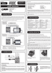
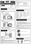
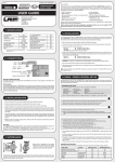
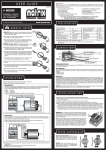
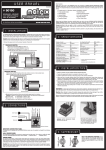
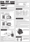
© LRP electronic GmbH 2008
RA00242
BRUSHLESS + BRUSHED
ORDER NO.:
80400
OVER 5.5T (BRUSHLESS - STAR)
OVER 7T (BRUSHED)
Dear Customer,
thank you for your trust in this LRP product. By purchasing a LRP SPX SUPER REVERSE speed-control, you have chosen one of the most advanced speed-controls of today. This speed-control with all of its
high-tech features and specially selected electronic components is offering great value for the money.
• 4 speed controls in 1 (Brushless, Brushed, Fwd/Brk/Rvs, Fwd/Brk)
• 4 fully adjustable modes
• AutoCell System
• Sensored Design
• Internal-Temp-Check system
• Advanced Digital
• 4, 5, and 6 cell optimised
• Small and Lighweight
• Big Power Capacitor
• IceDrive Design
• additional 2.6mm² Power-Wire-Set included
USER MANUAL
LRP electronic GmbH
Wilhelm-Enssle-Str. 132-134
73630 Remshalden
Germany
Please read the following instructions carefully before you start using your LRP SPX SUPER REVERSE speed
control. This user guide contains important notes for the safety, the use and the maintenance of this product.
Thus protecting yourself and avoid damages of the product.
Proceed according to the user guide in order to understand your LRP SPX SUPER REVERSE speed control better.
Please take your time as you will have much more joy with your product if you know it exactly.
This user manual shall be kept in a safe place. If another customer is using this product, this manual has to be
handed out together with it.
[email protected]
www.LRP.cc
1. INSTALLATION
• Connect the speed-control to the receiver (position: Channel 2)
3. SPECIFICATIONS
BRUSHLESS MOTOR:
The LRP SPX SUPER REVERSE comes pre-wired using common JST motor connectors. It‘s simply „plug
& play“ when you intend using a designated LRP Brushless motor, see picture below! You can of course
also use the supplied optional 2.6mm² power wires for a „hardwired“ setup without connectors.
Brushless + Brushed
yes
Typ. Voltage Drop (Brushed) 4
@20A - 0.013V
Brushless + Brushed adaption
AUTOMATIC
Rated Current (Brushed) 4
300A
Forward/Brake
yes
B.E.C.
6.0V/3.0A
Forward/Brake/Reverse
yes
High Frequency
yes
Case Size
33.1x37.6x14.9mm
Sensored Brushless System
yes
Weight (excl. wires)
24.5g
Multi-Protection-System
yes
Voltage Input
4.8-8.4V
Connectors
Std. Tamiya Style
Rec. Motor Limit for Star winds (Brushless)2
over 5.5 turns
Power Wires (additional)
2.6mm²
Rec. Motor Limit (Brushed) 2
über 7 turns
4, 5, 6 cell optimised
yes
Typ. Voltage Drop (Brushless) 4
@20A - 0.017V / phase
Internal-Temp-Check System
yes
Rated Current (Brushless) 4
300A / phase
C
Compatible winding styles (Brushless)
Star
B
4 adjustable modes
(NiMH/LiPo, Forward/Brake - Forward/
yes
Brake/Reverse, Power Profiles, Auto-Brake)
B
–
A
orange
+
yellow
C
blue
• Blue power-wire
Speedo MOT.A to motor „A“
• Yellow power-wire
Speedo MOT.B to motor „B“
• Orange power-wire
Speedo MOT.C to motor „C“
• Connect the hall sensor cable to the speed-control and the motor.
4
2
Transistors rating at 25°C junction temperature
measured at 7.2V
Specifications subject to change without notice.
A
Hall Sensor Wire
4. INSTALLATION TIPS
BRUSHED MOTOR:
B
–
A
orange
+
yellow
C
blue
• MOT.A (blue) and MOT.B (yellow) will be the combined „minus“ on the brushed motor.
• MOT.C (orange) wire will be „plus“ on the brushed motor.
+
Together to minus
• Doublecheck all connections before connecting the speed-control to a battery.
CAUTION: If battery is connected with reversed polarity it will destroy your speed-control!
Speedo BAT+ to battery „Plus“
• Red power-wire
Speedo BAT- to battery „Minus“
• Black power-wire
• The speed-control is now ready to be set-up (see section 6).
• Mount the speedo using the supplied thick/black doubled-sided tape.
• Position the speed-control where it is protected in the event of a crash.
• Install the speed-control so that you have easy access to the connector and buttons.
• Make sure there is enough clearance (about 3cm) between the speed-control, power-wires, antenna and
receiver. Avoid any direct contact between power components, the receiver or the antenna. This can cause
interference. If interference occurs, position the components at a different place in the model.
• The aerial should be run vertically up and away from the receiver. Avoid contact with any parts made of
carbon fibre or metal. If the aerial is too long, don’t coil up the excess length. It is better to cut it down to a
length of about 35 cm. See also the instructions supplied with your radio control system.
• Make sure there are enough cooling slits in the body. This will increase the performance and life of all the
electronic components.
HEATSINK: We recommend using the supplied heatsink in order to achieve best performance even under
extreme circumstances. Clean the heatsink and stickerplate before you attach the clear/thin Scotch 468MP
thermal tape to guarantee perfect heat dissipation.
Caution: Use ONLY the supplied clear/thin Scotch 468MP thermal tape to attach the heatsink! Do not us standard double sided tape to attach the heatsink as standard tape does not transfer heat!
Because of the physical principles of brushless technology, the speed-controls do get a little hotter then brushed
systems. Therefore it is required to let the speed-control cool down completely after every run. When running
in extreme conditions (high ambient temperature, low-turn motors, high gear ratios, etc.) we recommend using
the optional pre-wired cooling fan (#82511) which fits perfectly into the supplied heatsink.
MOT.A (Blue)
BAT - (Black)
MOT.B (Yellow)
BAT + (Red)
On/Off - Switch
MOT.C (Orange)
2. CONNECTIONS
LRP SPX SUPER REVERSE with heat sink.
Power Capacitor
Receiverwire
RECEIVER CONNECTING WIRE:
This speed-control is equipped with an LRP Multicon receiver
wire. As supplied, it will easily fit in all ordinary receivers.
Hall Sensor Connector
HALL SENSOR WIRE:
This bi-directional multipole wire (which comes with the motor and NOT the speed-control!) connects the
speed-control and the motor. Do not alter or modify this cable! There are replaceable/optional hall sensor wires
available:
• #81910 (20cm)
• #81920 (10cm)
POWER WIRES:
The LRP SPX SUPER REVERSE comes pre-wired using common Tamiya/JST battery connector and JST motor
connectors. It‘s simply „plug & play“ when you intend using a designated LRP Brushless motor! There is a
complete set of 2.6mm² power wires included, which allow you to use a „hardwired“ wire setup. The unique
splitted solder-tabs allow easy and convenient replacement of the power wires. Nevertheless some soldering
skills are required. Talk to your local hobbyshop if you are concerned about replacing the wires yourself. There
is a replacement power wire set available: #82505
CAUTION: Be very careful with the correct wire sequence since an incorrect connection may damage the
speed-control! Avoid creating solder bridges on the solder-tabs and isolate all connections carefully. Avoid
soldering longer then 5sec per soldering joint.
Mount the power-capacitor in a position where it is protected in the event of a
crash. The best place is right next to the speed-control (see picture). Secure it
with doublesided tape.
5. SUPPRESSION
ONLY FOR BRUSHED MOTORS! Motors with no
capacitors or not enough capacitors may interfere
with the speed-control. To avoid this, solder the
supplied capacitors to your motor (see picture).
8. SPECIAL FEATURES
6. RADIO / SPEED-CONTROL SET-UP
In setup mode the LRP SPX SUPER REVERSE stores every step when you press the SET button. All the settings will
be stored in the speed-controls memory even if the speed-control will be disconnected from the battery.
TRANSMITTER SETTINGS
Setup the following basic functions on your transmitter (if available):
Internal-Temp-Check System: the LRP SPX SUPER REVERSE allows you to read-out the maximum internal temperature that the speedo reached. To save it to the memory you have to briefly apply brakes after the run
before you turn the switch off. You can convienently read-out the temperature back in the pits since it remains
stored until you turn it on the next time regularly (which will reset the memory). This new feature allows you to
accurately check if all is running well or if you‘re close to shutdown already.
How to read-out the temperature:
Switch at „OFF“ position.
Keep MODE button pressed while you turn switch to „ON“ (then release button)
SET LED will start to flash red (MODE LED is off), now count the number of flashes.
Throttle travel
High ATV, EPA
maximum
Brake travel
Low ATV, EPA, ATL
maximum
Throttle exponential
EXP, EXPO
start with 0
Neutral trim
SUB Trim
centre
Servo reverse
Throttle reverse
any setting, don‘t change after set-up procedure!
Basics:
• Thermal shutdown of the speedo would occur at 6 flashes.
• The higher the number of flashes, the cooler the speedo ran (e.g. the better it is!)
• Every flash equals to ~8°C temperature decrease
If your transmitter doesn‘t offer any of above functions, it‘s already in „basic setup“ mode.
• Ensure that the speed-control is not connected to the drive battery and is switched off.
• Remove motor pinion or ensure that the wheels of the model are free to rotate.
• Switch the transmitter on and set the transmitter throttle stick to neutral.
Example:
you count 10 flashes after the run
10 - 6 = 4 (e.g. 4 flashes „away“ from shutdown)
4 x 8°C = 32°C (e.g. you are 32°C away from thermal shutdown and therefore safe!)
AutoCell System: Ready for the next battery technology – LiPo batteries! LRP’s exclusive and smart
• Connect the speed-control to the battery, and switch the unit on.
• Hold the SET button pressed for at least 3sec using the supplied plastic screwdriver.
You entered setup mode and the SET LED flashes red (it will flash until the setup is completed).
• Leave transmitter in neutral position and press the SET button once.
Neutral setting is stored , MODE LED flashes green and the motor beeps.
• Hold full throttle on transmitter and press the SET button once.
Full-throttle setting is stored, MODE LED flashes red.
• Hold full reverse on transmitter and press the SET button once.
Reverse setting is stored, LED‘s glow red (MODE) and red (SET).
to your transmitter, but never mind since you can simply disconnect the receiver lead from the receiver and
change the MODE settings as described in section 7 „Mode Programming“.
IceDrive Design: LRP’s secret IceDrive Design results in lower speedo temperature under all racing conditions
and for both brushless + brushed. Sorry, no further details to be disclosed. Simply a step ahead of the competition!
Works-Default-Settings: All LRP speed-controls come factory-adjusted (defaults are grey-shaded abo-
CHECKING THE FUNCTIONS:
Check the LED‘s when moving your throttle stick and you will see if everything is setup correctly.
STATUS
MODE LED
SET LED
off
red
Neutral (automatic brake inactive)
--
Neutral (automatic brake active)
--
red
off
Forward
partial throttle
green
off
green
red
Forward
full throttle
Brake/Reverse
partial brake/reverse
red
off
Brake/Reverse
full brake/reverse
red
red
7. MODE PROGRAMMING
All modes are available for brushless and brushed motors (speedo adapts automatically). The LRP SPX SUPER
REVERSE features 4 modes which enable you to adjust it to YOUR special requirements. The factory settings
are shown in grey colour.
• How to get into „programming the modes“
• How to check the stored values
Automatic Brushless / Brushed Adaption: The LRP exclusive Automatic Brushless/Brushed Adaptation detects the connected motor type during turn-on/initialisation and adjusts the correct brushless or brushed
operation automatically. No adjustments required by yourself, apart from the correct connection of each motor
type (don‘t forget the hall-sensor-wire for brushless!).
CAUTION: Keep in mind, when swopping between brushless and brushed motors, that the chosen mode values
will be identical!
Changing Mode settings without the transmitter: At race events you usually do not have access
• This completes the setup procedure and your LRP SPX SUPER REVERSE is ready to use.
• If you make a mistake during the setup procedure, don‘t worry: Disconnect the battery for about 10sec and
start again from the first step.
• At the end of each run switch of the car, and then switch off the transmitter.
• At the start of each run switch on the transmitter first, then switch on the car.
• For storage of the car, disconnect the drive battery at any time!
FUNCTION
AutoCell System ensures that LiPo batteries can be used safely without accidentially deep-discharging of
the cells. The motor function will be shut-off and the SET LED will flash if the system recognises very low
battery voltage.
TIP: We recommend using value 2 for 4-6 cells NiMH racing purposes, which disengages the LiPo protection.
Press MODE button for 3 or more seconds.
Count the number of flashes of the red SET-LED
(1x = value 1, 2x = value 2, etc.).
ve). If you loose track of the modes, you can restore the works default settings. With the transmitter switched
on, hold the SET button pressed while you switch on the speed-control. This simple action returns the unit to
the LRP works default settings.
Power Capacitor: Never disconnect the power-capacitor! It is required for proper function, a special SuperLow ESR type has been choosen, which offers increased punch and additional protection, therefore only use
genuine LRP power capacitors.
Sensored Brushless Technology: Advanced Digital allows the perfect knowledge of the brushless
motor’s magnet position. This results in perfect motor control at high and low RPM‘s, as well as perfect
brake control.
Multi-Protection System: The perfect protection against short-circuits (motor), overload and overheating. If your speed-control faces overload, the motor function will be shut-off for protection and the SET LED will
flash, although the steering function is maintained. Let the speed-control cool down for a few minutes. If you
experience frequent shutdowns, check for the following:
• Correct gear ratio (refer to motor manual for gearing recommendations)
• ADPC setting too high (higher value will heat up motor and speed-control excessively)
• Motor is too strong or motor is damaged.
9. TROUBLESHOOTING GUIDE
EXPLANATION: If no remark, cause can be either with brushless or brushed motor. If „BM“ is indicated, cause
only relating to brushed motor.
SYMPTOM
CAUSE
REMEDY
Servo is working, no motor function.
Speed-control plugged in incorrectly
Plug speed-control in Ch 2
Overload protection activated
Allow speed-control to cool down
Wiring problem
Check wires and plugs
Motor defective
Replace motor
BM - Motor brushes stuck
Check that brushes are moving freely
Speed-control defective
Send in product for repair
Speed-control plugged in incorrectly
Plug speed-control in with correct polarity
Crystal defective
Replace components one by one.
• How to change the value
• How to get to the next Mode
• How to leave the programming mode
Press SET button to increase value by one step.
Press MODE button once.
If you are in MODE.4, press the MODE button
one more time
• Table of settings, values and modes: see below (grey-shaded values show „works default settings“)
No servo and no motor function.
Receiver defective
MODE.1 - AutoCell SYSTEM
we recommend using value 2 for 4-6 cells NiMH racing purposes, which disengages the LiPo protection.
MODE LED
Value 1
Value 2
Green
LiPo
Mode
NiMH
Racing Mode
MODE.2 - FORWARD/BRAKE/REVERSE - FORWARD/BRAKE
the LRP SPX SUPER REVERSE contains 4 speed-controls in 1! Brushless or brushed it adapts automatically
and here you can select between forward/brake/reverse and forward/brake „racing style“ operation.
MODE LED
Value 1
Value 2
Red
Forward
Reverse
Forward
Brake
MODE LED
Value 1
Value 2
Value 3
Value 4
Green/Red
(alternate)
Smooth
Linear
Progressive
Aggressive
Green/Red
(same time)
No Automatic
Brake
Value 1
Send in product for repair
BM - Motor connected incorrectly
Connect motor correctly
Insufficient performance.
E.g. poor brake power, topspeed or
acceleration..
Motor pinion too big or gear ratio too long.
Use smaller motor pinion/shorter gear ratio
Transmitter settings changed after set-up
Repeat set-up procedure
BM - Motor worn out
Maintain motor
Motor defective
Replace motor
Value 2
Value 3
Motor never stops, runs at constant
slow speed
Radio interference
MODE.4 - AUTO-/DRAGBRAKE
allows you to set a slight braking action which is applied in the neutral range. This enables you to simulate the
feel of a brushed motor and also hold the throttle on longer when entering a turn. Your car also has more front
traction with this setting.
For brushless motors you achieve the same natural slowdown as a brushed motor with no autobrake when
you set value 1-2 (for motors with bonded magnets) or 0-1 (for motors with sintered magnets).
Value 0
Speed-control defective
Motor runs in reverse when accelerating forward on the transmitter.
Speed-control overheats or switches
off frequently.
MODE.3 - POWER PROFILES
allows you to adjust the LRP SPX SUPER REVERSE to your likes. Either you run on slippery or high-traction
surfaces, we have incorporated a profile for you!
Higher value means more overall power and more aggressive throttle response.
MODE LED
Transmitter defective
Value 4
increasing from low (#1) to high (#4) autobrake settins
Speed-control defective.
Send in product for repair
Motor stronger than motorlimit or input voltage
too high
Use only motors and batteries which are within
the specifications of the speed-control
Motor pinion too big or gear ratio too long.
Use smaller motor pinion/shorter gear ratio
Drive train or bearing problems.
Check or replace components.
Model used too often without cool-down periods
Let speed-control cool down after every run
Transmitter settings changed after set-up
Repeat set-up procedure
Humidity/water in speed-control
Immediately unplug and dry speed-control
Speed-control defective
Send in product for repair
BM - Motor suppressors not sufficient
Solder capacitors to motor
Receiver or antenna too close to power wires,
motor, battery or speed-control.
Receiver aerial too short or coiled up
See „Installation Tips“ and „Installation“
Receiver defective, too sensitive;
Transmitter defective, transmitter output power
too low, servo problem
Replace components one by one
Only use original manufacturers crystals
Poor battery connection
Check plugs and connecting wires
Transmitter batteries empty
Replace / recharge transmitter batteries
Transmitter antenna too short
Pull out antenna to full length
RA00245
!
© LRP electronic GmbH 2008
WARNHINWEISE
!
WARNING NOTES
Kein Spielzeug. Nicht für Kinder unter 14 Jahren geeignet.
No toy. Not suitable for children under 14 years.
Bewahren Sie das Produkt außerhalb der Reichweite von kleinen
Kindern auf.
Keep the product out of the reach of children.
Beachten Sie unbedingt die folgenden Hinweise, da diese Ihr
Produkt zerstören können und die Gewährleistung ausschließen. Nichtbeachtung dieser Hinweise können zu Sach- und
Personenschäden und schweren Verletzungen führen!
• Lassen Sie das Produkt niemals unbeaufsichtigt, solange es
eingeschaltet, in Betrieb oder mit einer Stromquelle verbunden
ist. Im Falle eines Defekts könnte dies Feuer am Produkt oder
seiner Umgebung verursachen.
• Wickeln Sie Ihr Produkt niemals mit Plastikfolie, Metallfolie oder
Ähnlichem ein, sondern sorgen Sie im Gegenteil für Frischluft.
• Vermeiden Sie falschen Anschluss oder Verpolung des Pro-
dukts.
• Alle Kabel und Verbindungen müssen gut isoliert sein. Kurz-
schlüsse können unter Umständen das Produkt zerstören.
• Dieses Produkt oder andere elektronische Komponenten dürfen
niemals mit Wasser, Öl, Treibstoffen oder anderen elektrisch
leitenden Flüssigkeiten in Berührung kommen, da diese Mineralien enthalten können, die elektronische Schaltkreise korrodieren lassen. Bei Kontakt mit diesen Stoffen müssen Sie sofort
den Betrieb einstellen und das Produkt sorgfältig trocknen.
• Die Originalstecker und Originalkabel dürfen niemals verändert
oder abgeschnitten werden.
• Öffnen Sie niemals das Produkt und löten Sie keinesfalls auf der
Platine oder anderen Komponenten
• Benutzen Sie Ihr Produkt nicht mit geöffnetem, beschädigtem
oder fehlendem Gehäuse oder in Schrumpfschlauch. Dies mindert den Störschutz, kann Kurzschlüsse verursachen und das
Produkt beschädigen.
• Entnehmen Sie immer den Akku aus Ihrem Produkt bzw. trennen Sie das Produkt von der Stromquelle,
wenn das Produkt nicht verwendet wird.
• Schalten Sie immer zuerst Ihren Sender ein, bevor Sie den Empfänger oder Fahrtenregler einschalten.
Der Empfänger könnte Störsignale auffangen, Vollgas geben, und Ihr Modell beschädigen. Beim
Ausschalten beachten Sie die umgekehrte Reihenfolge. Erst Empfänger und Fahrtenregler ausschalten, dann Sender ausschalten.
• Geben Sie keinesfalls Vollgas, wenn der Motor noch nicht eingebaut ist. Durch die extrem hohen
Drehzahlen ohne Last kann der Motor beschädigt werden.
• Löten Sie bei Verwendung dieses Reglers niemals eine Schottky-Diode an den Motor.
• Solange der Motor an den Regler angeschlossen ist, dürfen Sie niemals den Motor mit einem separa-
ten Akku oder mit einem Motor-Einlaufgerät laufen lassen.
• Stellen Sie sicher, dass die Kühlbleche der Fets sich niemals berühren - Kurzschlußgefahr!
• Verändern Sie niemals die Polarität des Empfängersteckers.
• Schließen Sie sämtliche Teile der Ausrüstung sorgfältig an. Falls sich die Verbindungen durch Vibra-
tionen lösen, können Sie die Kontrolle über das Modell verlieren.
• Vermeiden Sie es beim Wechseln der Powerkabel länger als 5 Sekunden je Lötstelle zu löten, um
eine Beschädigung der Bauteile durch Überhitzung auszuschließen. Verwenden Sie zum Löten eine
leistungsstarke Lötstation mit mind. 60W.
Pay close attention to the following points, as they can destroy the product and void your warranty. Non-observance of
these points can lead to property damage, personal and severe
injuries!
• Never leave the product unsupervised while it is switched on,
in use or connected with a power source. If a defect occurs, it
could set fire to the product or the surroundings.
• Never wrap your product in plastic film, metal foil or similar. In
fact, make sure it gets enough fresh air.
• Avoid incorrect connections or connections with reversed pola-
rity of the product.
• All wires and connections have to be well insulated. Short-cir-
cuits can possibly destroy the product.
• Never allow this product or other electronic components to come
in contact with water, oil or fuels or other electroconductive liquids, as these could contain minerals, which are harmful for
electronic circuits. If this happens, stop the use of your product
immediately and let it dry carefully.
• Never cut off or modify the original plugs and original wires.
• Never open the product and never solder on the PCB or other
components.
• Never use this product when the case is open, damaged or mis-
sing or when the product is wrapped in a shrink-fit tube. This
will reduce protection, may cause short circuits and damage
the product.
• Always remove the battery from your product or disconnect the
product from the power source, if the product is not in use.
• Always switch on your transmitter first before you switch on the receiver or the speed control. The
receiver could receive interference signals, start full acceleration and damage your model. When
you switch off, make sure you do so in the reverse sequence. First switch off the receiver and speed
control, then switch off the transmitter.
• Never apply full throttle if the motor is not installed. Due to the extremely high RPMs without load,
the motor can get damaged.
• Never solder a Schottky diode to the motor when you are using this speed-control.
• If the speed-control is connected to the motor, never run the motor directly with a separate battery
or run-in device.
• Ensure, that the output stages (FETs) never touch a metal surface - Short-circuit hazard!
• Never change the polarity of the receiver connector.
• Always wire up all the parts of the equipment carefully. If any of the connections come loose as a •
result of vibration, you could loose control over your model.
• Avoid soldering longer then 5 seconds per soldering joint when replacing the power wires to prevent
possible damage to the product due to overheating of the components. Use a high power soldering
station with at least 60W for soldering.
• The manufacturer can not be held responsible for damages, which are a result of non-observan-
ce of the warning notes and security advices.
• Der Hersteller kann nicht für Schäden verantwortlich gemacht werden, die infolge von Nichtbe-
achtung der Sicherheitshinweise und Warnungen verursacht werden.
Das Symbol einer durchgestrichenen Abfalltonne auf Rädern bedeutet, dass das Produkt in
der Europäischen Union einer getrennten Müllsammlung zugeführt werden muss. Diese Produkte dürfen nicht über den unsortierten Hausmüll entsorgt werden.
The crossed-out wheeled bin means that within the European Union the product must be
taken to seperate collection at the product end-of-life. Do not dispose of these products as
unsorted municipal waste.
ALLGEMEINE GEWÄHRLEISTUNGS- UND REPARATURBESTIMMUNGEN
Produkte der LRP electronic GmbH (nachfolgend „LRP“ genannt) werden nach strengsten Qualitätskriterien
gefertigt. Wir gewähren die gesetzliche Gewährleistung auf Produktions- und Materialfehler, die zum Zeitpunkt
der Auslieferung des Produkts vorhanden waren. Für gebrauchstypische Verschleißerscheinungen wird nicht
gehaftet. Diese Gewährleistung gilt nicht für Mängel, die auf eine unsachgemäße Benutzung, mangelnde
Wartung, Fremdeingriff oder mechanische Beschädigung zurückzuführen sind.
Dies liegt unter Anderem vor bei:
• Stecker abgeschnitten bzw. kein verpolsicheres Stecksystem
• Empfängerkabel und/oder Schalter beschädigt
• Gehäuse mechanisch beschädigt
• Wasser/Wasserrückstände im Gehäuse
• Mechanische Beschädigung der Bauteile/Platine
• Auf der Platine gelötet (Ausnahme außen liegende Lötlaschen)
• Akkuseitig verpolt
Bevor Sie dieses Produkt zur Reparatur einsenden, prüfen Sie bitte zunächst alle anderen Komponenten in ihrem
Modell und schauen Sie ggf. in der Fehlerfibel des Produktes (sofern vorhanden) nach, um andere Störquellen
und Bedienfehler auszuschließen. Sollte das Produkt bei der Überprüfung durch unsere Serviceabteilung
keine Fehlfunktion aufweisen, müssen wir Ihnen hierfür die angefallenen Bearbeitungskosten laut Preisliste
berechnen.
Mit der Einsendung des Produktes muss der Kunde mitteilen, ob das Produkt in jedem Fall repariert werden
soll. Sollte kein Gewährleistungs- oder Garantieanspruch bestehen, erfolgt die Produktüberprüfung und ggf.
Reparatur in jedem Falle kostenpflichtig gemäß unserer Preisliste. Ein Gewährleistungs- oder Garantieanspruch
kann nur anerkannt werden, sofern eine Kopie des Kaufbelegs beigefügt ist. Auf Ihre ausdrückliche Anforderung
erstellen wir einen kostenpflichtigen Kostenvoranschlag. Wenn Sie nach Zusendung des Kostenvoranschlags
den Auftrag zur Reparatur erteilen, entfallen die Kostenvoranschlagskosten. An unseren Kostenvoranschlag
sind wir zwei Wochen ab Ausstellungsdatum gebunden. Für eine schnelle Abwicklung Ihres Servicefalls legen
Sie bitte eine ausführliche Fehlerbeschreibung und ihre Adressdaten der Einsendung bei.
Die von LRP angegebenen Werte über Gewicht, Größe oder Sonstiges sind als Richtwert zu verstehen.
LRP übernimmt keine formelle Verpflichtung für derartige spezifische Angaben, da sich durch technische
Veränderungen, die im Interesse des Produkts vorgenommen werden, andere Werte ergeben können.
Bei LRP 25 Jahre Garantie Produkten gelten zusätzlich die Garantiebestimmungen auf der LRP
25 Jahre Garantiekarte. Die ursprünglichen beim Kauf des Produktes entstehenden gesetzlichen
Gewährleistungsansprüche gegenüber dem Verkäufer sowie zwingende gesetzliche Haftungsregelungen nach
dem Produkthaftungsgesetz bleiben hiervon unberührt.
LRP-Werks-Service:
• Produkt mit Kaufbeleg und Fehlerbeschreibung bruchsicher verpacken.
• Einsenden an:
LRP electronic GmbH – Serviceabteilung
Wilhelm-Enssle-Str. 132-134, 73630 Remshalden, Deutschland
• LRP repariert das Produkt.
• Rücksendung an Sie per Nachnahme.
Technik + Service Hotline:
D: 0900 577 4624 (0900 LRP GMBH) (0.49€/Minute aus dem dt. Festnetz. Mobilfunkpreise können abweichen)
A: 0900 270 313 (0.73€/Minute aus dem öst. Festnetz. Mobilfunkpreise können abweichen)
eMail: [email protected]
Web: www.LRP.cc
Falls ein zurückgesandtes, defektes Produkt von LRP nicht mehr produziert wird, und wir dieses nicht reparieren
können, so erhalten Sie statt dessen ein mindestens gleichwertiges Produkt aus einer der Nachfolgeserien.
REPAIR PROCEDURES / LIMITED WARRANTY
All products from LRP electronic GmbH (hereinafter called “LRP”) are manufactured according to the highest
quality standards. LRP guarantees this product to be free from defects in materials or workmanship for 90
days (non-european countris only) from the original date of purchase verified by sales receipt. This limited
warranty doesn’t cover defects, which are a result of misuse, improper maintenance, outside interference or
mechanical damage.
„This applies among other things on:
• Cut off original power plug or not using reverse polarity protected plugs
• Receiver wire and/or switch wire damaged
• Mechanical damage of the case
• Humidity/Water inside the speed control
• Mechanical damage of electronical components/PCB
• Soldered on the PCB (except on external solder-tabs)
• Connected speed-control with reversed polarity“
To eliminate all other possibilities or improper handling, first check all other components in your model and the
trouble shooting guide, if available, before you send in this product for repair. If products are sent in for repair,
which do operate perfectly, we have to charge a service fee according to our pricelist.
With sending in this product, the customer has to advise LRP if the product should be repaired in either case. If
there is neither a warranty nor guarantee claim, the inspection of the product and the repairs, if necessary, in
either case will be charged with a fee at the customers expense according to our price list. A proof of purchase
including date of purchase needs to be included. Otherwise, no warranty can be granted. For quick repair- and
return service, add your address and detailed description of the malfunction.
If LRP no longer manufactures a returned defective product and we are unable to service it, we shall provide
you with a product that has at least the same value from one of the successor series.
The specifications like weight, size and others should be seen as guide values. Due to ongoing technical
improvements, which are done in the interest of the product, LRP does not take any responsibility for the
accuracy of these specs.
With LRP 25-Years Warranty products, the warranty terms on the LRP 25-Years Warranty card do also
apply. The legal warranty claims, which arose originally when the product was purchased, shall remain
unaffected.
LRP-Distributor-Service:
• Package your product carefully and include sales receipt and detailed description of malfunction.
• Send parcel to your national LRP distributor.
• Distributor repairs or exchanges the product.
• Shipment back to you usually by COD (cash on delivery), but this is subject to your national LRP
distributor‘s
general policy.