1
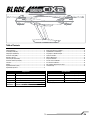
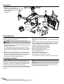
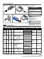
®
Instruction Manual
NOTICE
All instructions, warranties and other collateral documents are subject to change at the sole discretion of Horizon Hobby, LLC. For up-to-date product literature,
visit horizonhobby.com and click on the support tab for this product.
Meaning of Special Language
The following terms are used throughout the product literature to indicate various levels of potential harm when operating this product:
NOTICE: Procedures, which if not properly followed, create a possibility of physical property damage AND a little or no possibility of injury.
CAUTION: Procedures, which if not properly followed, create the probability of physical property damage AND a possibility of serious injury.
WARNING: Procedures, which if not properly followed, create the probability of property damage, collateral damage, and serious injury OR create a high probability of superficial injury.
WARNING: Read the ENTIRE instruction manual to become familiar with the features of the product before operating. Failure to operate the product
correctly can result in damage to the product, personal property and cause serious injury.
This is a sophisticated hobby product. It must be operated with caution and common sense and requires some basic mechanical ability. Failure to operate this
Product in a safe and responsible manner could result in injury or damage to the product or other property. This product is not intended for use by children without
direct adult supervision. Do not use with incompatible components or alter this product in any way outside of the instructions provided by Horizon Hobby, LLC.
This manual contains instructions for safety, operation and maintenance. It is essential to read and follow all the instructions and warnings in the manual, prior to
assembly, setup or use, in order to operate correctly and avoid damage or serious injury.
Age Recommendation: Not for children under 14 years. This is not a toy.
General Safety Precautions and Warnings
• Always keep a safe distance in all directions around your model to avoid collisions or injury. This model is controlled by a radio signal subject to interference
from many sources outside your control. Interference can cause momentary
loss of control.
• Always operate your model in open spaces away from full-size vehicles, traffic
and people.
• Always carefully follow the directions and warnings for this and any optional
support equipment (chargers, rechargeable battery packs, etc.).
• Always keep all chemicals, small parts and anything electrical out of the reach
of children.
• Always avoid water exposure to all equipment not specifically designed and
protected for this purpose. Moisture causes damage to electronics.
• Never place any portion of the model in your mouth as it could cause serious
injury or even death.
• Never operate your model with low transmitter batteries.
• Always keep aircraft in sight and under control.
• Always move the throttle fully down at rotor strike.
• Always use fully charged batteries.
• Always keep transmitter powered on while aircraft is powered.
• Always remove batteries before disassembly.
• Always keep moving parts clean.
• Always keep parts dry.
• Always let parts cool after use before touching.
• Always remove batteries after use.
• Never operate aircraft with damaged wiring.
• Never touch moving parts.
CAUTION: The ESCs for the 350 QX2 are not compatible with any other product, and the 350 QX2 is not compatible with any other ESCs. Use of any other
ESCs on the 350 QX2 will cause a crash, which may result in property damage and/or personal injury.
WARNING AGAINST COUNTERFEIT PRODUCTS: If you ever need to replace a Spektrum component found in a Horizon Hobby product, always purchase
from Horizon Hobby, LLC or a Horizon Hobby authorized dealer to ensure authentic high-quality Spektrum product. Horizon Hobby, LLC disclaims all support and warranty with regards, but not limited to, compatibility and performance of counterfeit products or products claiming compatibility with DSM or Spektrum.
The Blade 350 QX2 has many more features than other Blade quadcopters. Please take the time to read this manual and understand the functions this aircraft
contains before flying.
EN
2
®
Table of Contents
Box Contents ......................................................................................................4
Charging Warnings..............................................................................................4
Low Voltage Cutoff (LVC) .....................................................................................4
Charging the Flight Battery .................................................................................5
Transmitter Setup (BNF) ......................................................................................5
Mounting a Camera ............................................................................................6
Connecting the Flight Battery ..............................................................................7
Transmitter Control Layout (RTF) .........................................................................7
Power On ............................................................................................................7
Binding ...............................................................................................................8
Flight Mode Switches (RTF).................................................................................9
Flight Modes Explained .......................................................................................9
Audible Alerts and LED Codes ...........................................................................10
GPS Functionality of the 350 QX2......................................................................12
Flight Guidelines and Warnings .........................................................................13
Preparing the 350 QX2 for Flight .......................................................................13
Flying the 350 QX2 ...........................................................................................14
Airframe Maintenance.......................................................................................15
Compass Calibration .........................................................................................16
Pressure Sensor Calibration ..............................................................................16
Accelerometer Calibration .................................................................................16
ESC and Motor Assignment Procedure ..............................................................17
Troubleshooting ................................................................................................17
Components
Specifications
Airframe
Blade 350 QX2 Quadcopter
Length
18.30 in (465mm)
Motors
4x Brushless Outrunner Motor, 1100Kv
Height
7.48 in (190mm)
ESCs
4x 10-Amp Brushless ESC
Main Rotor Diameter
22.80 in (580mm)
Battery
3000mAh 3S 11.1V 20C Li-Po Battery
Flying Weight
Charger
3S DC Li-Po Balancing Charger with 5A AC Power Supply
To register your product online, visit www.bladehelis.com
Transmitter
Spektrum™ DX4 DSMX® 4-Channel Transmitter
3
35.5 oz (760 g)
EN
Box Contents
• Blade® 350 QX2
• 3000mAh 3S 11.1V 20C Li-Po Battery
• 3S DC Li-Po Balancing Charger with 5A AC Power Supply
• Spektrum™ DX4 DSMX® 4-Channel Transmitter (RTF)
• 4 AA Batteries (RTF)
• Camera Mount
Charging Warnings
The Battery Charger (EFLC3016) included with your quadcopter has been
designed to safely charge the Li-Po battery.
CAUTION: All instructions and warnings must be followed exactly.
Mishandling of Li-Po batteries can result in a fire, personal injury and/or
property damage.
• By handling, charging or using the included Li-Po battery, you assume all risks
associated with lithium batteries.
• If at any time the battery begins to balloon or swell, discontinue use immediately. If charging or discharging, discontinue and disconnect. Continuing to
use, charge or discharge a battery that is ballooning or swelling can result in
fire.
• Always store the battery at room temperature in a dry area for best results.
• Always transport or temporarily store the battery in a temperature range of
40–120º F (5–49° C). Do not store battery or model in a car or direct sunlight.
If stored in a hot car, the battery can be damaged or even catch fire.
• Always charge batteries away from flammable materials.
• Always inspect the battery before charging.
• Always disconnect the battery after charging, and let the charger cool between
charges.
• Always constantly monitor the temperature of the battery pack while charging.
• ONLY USE A CHARGER SPECIFICALLY DESIGNED TO CHARGE LI-PO BATTERIES. Failure to charge the battery with a compatible charger may cause a fire
resulting in personal injury and/or property damage.
• Never discharge Li-Po cells to below 3V under load.
• Never cover warning labels with hook and loop strips.
• Never leave charging batteries unattended.
• Never charge batteries outside recommended levels.
• Never charge damaged batteries.
• Never attempt to dismantle or alter the charger.
• Never allow minors to charge battery packs.
• Never charge batteries in extremely hot or cold places
(recommended between 40–120° F) or (5–49° C) or place in direct sunlight.
Low Voltage Cutoff (LVC)
Low voltage cutoff (LVC) protects the Li-Po battery from over-discharge in flight
and activates when the battery reaches a preset value. When the battery is
discharged to the cutoff point, the aircraft will display rapidly flashing red, green
and blue LEDs to warn you it’s time to land. When you see this LED code, land
immediately to prevent over-discharge and damage to the battery.
When the LVC is activated, you have approximately 2 minutes until the battery is
depleted and can no longer maintain a hover. Repeated flying to LVC will damage
the battery.
EN
NOTICE: Crash damage and battery damage are not covered under warranty.
IMPORTANT: Always disconnect and remove the Li-Po battery from the aircraft
after each flight. Charge your Li-Po battery to about half capacity before storage.
During storage, make sure the battery charge does not fall below 3V per cell.
A connected battery will result in trickle discharge.
4
Charging the Flight Battery
1a
Charger Specifications
• Input Voltage: 10.5–15V DC
• Charge Current: 3.5A
1b
The Battery Charging Process
2
1. Connect the AC power supply to the charger.
2. Connect the AC power supply to an AC power source.
The green LED blinks.
3. Connect the battery to the charger. The red LED
blinks, indicating charging. When the battery nears
full charge, the red and green LEDs blink, indicating
cell balancing.
4. Disconnect the battery when the green LED glows
solid.
3
LED Indications
Green Blinking: Ready to Charge
Red Blinking: Charging
Red & Green Blinking: Cell Balancing
Green Solid: Charging Complete
Red Solid: Error
CAUTION: Overcharging a battery can cause
a fire.
NOTICE: If using a battery other than the included
Li-Po battery, refer to your battery manufacturer’s
instructions for charging.
Transmitter Setup
CAUTION: When using a Futaba transmitter with a Spektrum DSM module, you must reverse the throttle channel and rebind. Refer to your Spektrum module manual for binding
and failsafe instructions. Refer to your Futaba transmitter manual for instructions on reversing the throttle channel.
Transmitter
Model
Type
Reverse
Setup
Throttle Cut Mode Setup
Setup
DX4e (New)*
w/3-position
switch
N/A
N/A
N/A
N/A
DX5e (New)*
w/3-position
switch
N/A
N/A
N/A
N/A
ACT
Travel Adj: GEAR POS (0) GEAR: ↑100%;
GEAR/F MODE POS (1) GEAR: ↓40%
FLAPS: Norm ←↑100; LAND ↓100
MIX 1: ACT; GEAR → GEAR ACT
RATE D 0%; U + 100%
SW MIX TRIM INH
SUB TRIM THRO ↑ 15-20%
GEAR 0; Mix 0 = SMART Mode
Acro
THRO-N
ELEV-N
GEAR-R
AILE-N
RUDD-N
FLAP-N
Travel Adj: GEAR (0)↑100%;
GEAR (1) ↓40%
MIX 1: FLAP → Gear OFF/ON
RATE → -50%
0%
SW: MIX OFFSET: 0
GEAR (0); Mix (0) = SMART Mode
DX6i
DX7/7SE
DX7S
DX8
Acro
Acro
Acro
DX6/DX9/DX18 Acro
FLAP-R (6)
Others-N
AUX1-R
Others-N
AUX1-R
Others-N
AUX1-R
Others-N
N/A
Set To:
Trainer
Set To:
Trainer
Set To:
I (BIND)
Switch Positions
Throttle Cut
Return Home
Position 0 = SMART Mode
Position 1 = AP Mode
Position 2 = Stability Mode
Position 0 = SMART Mode
Position 1 = AP Mode
Position 2 = Stability Mode
Lower throttle trim
until motors stop
turning
Press and Hold TRAINER/
BIND Release to EXIT
Lower throttle trim
until motors stop
turning
Press and Hold TRAINER/
BIND Release to EXIT
Press throttle cut
FLAP Position 0 = OFF
FLAP Position 2 = Return
Home
Lower throttle trim
until motors stop
turning
FLAP Pos 0
= OFF
FLAP Pos 1
= Return Home
Press
Trainer
FLAP Pos 0 = OFF
FLAP Pos 2 = Return
Home
Press Trainer/Bind
FLAP Pos 0
= OFF
FLAP Pos 2
= Return Home
Press I (BIND)
D (FLAP) Pos 0 = OFF
D (FLAP) Pos 2 = Return
Home
GEAR 1; Mix 0 = AP Mode
GEAR 1; Mix 1 = Stability Mode
GEAR (1); Mix (0) = AP Mode
GEAR (1); Mix (1) = Stability Mode
Switch Select:
Move Gear to F MODE (F MODE:GEAR)
Leave FLAPS as AUX1
Set All Others to INH
MIX 1: GER > GER
RATE:
0%
-100%
OFFSET: 0%; TRIM: INH; SW: Mix0
F MODE (0) = SMART Mode
F MODE (1) = AP Mode
F MODE (1); HOLD (1) = Stability Mode
F MODE (0) = SMART Mode
Switch Select: F-Mode to Gear;
Flap to Aux 1
All Others to INH
F MODE (1) = AP Mode
F MODE (2) = Stability Mode
B (0) = SMART Mode
Channel Assign: NEXT
1-4: N/A
5 Gear: B
6 AUX1: H
7-10: INH
B (1) = AP Mode
B (2) = Stability Mode
* Old versions of the DX4e and DX5e (with 2-position channel 5 switches) are not recommended for the 350 QX2. Only Smart Mode and Stability Mode will be available with GPS On.
5
EN
Mounting a Camera
IMPORTANT: Consult local laws and ordinances before installing and operating any type of photograph-capable or video recording device in this product.
Assembling the Isolation Mount
2
1
Installing the Included Camera Frame to the Isolation Mount
* Camera not included
Copper Foil Sheilding Instructions
The Blade® 350 QX2 includes two adhesive-backed,
metal-foil sheets to provide GoPro® users with an
extra measure of RF-shielding.
1. Fold the inner “T” sheet (A) around the
camera with the metallic side facing away
from the camera so it covers the top, sides
and back. DO NOT peel off the backing.
A
B
2. Peel the backing off the rectangular sheet (B).
3. Wrap sheet B around the back of sheet A,
sealing all the rear edges and holding
everything together.
DO NOT peel off
the backing
1 A
4. The shield is removable and is held in place
by the 350 QX2 camera mount.
*
The front and bottom of the camera are left
unshielded to allow any RF noise to radiate out
and away from the 350 QX2.
2
B
3
4
B
A
WARNING: Always disable Wi-Fi before flying the Blade 350 QX2 with a GoPro camera. If Wi-Fi is not disabled, interference may cause loss of control,
which could result in a crash.
EN
6
Connecting the Flight Battery
4
3
2
3
1
2
1
Transmitter Control Layout
Mode Switch
0 - Smart Mode
1 - AP Mode
2 - Stability Mode
Return Home Switch
Bind Button/
Motor Stop
Rudder/Yaw
(Modes 2 and 1)
Aileron/Roll
(Modes 2 and 1)
Throttle/Altitude
(Mode 2)
Elevator/Pitch
(Mode 1)
Elevator/Pitch
(Mode 2)
Throttle/Altitude
(Mode 1)
Power Switch
Power On
Transmitter
(Mode 2 )
350 QX2
RTF
1
2
Throttle
3
4
7
EN
Binding
The transmitter is bound to the model at the factory. If
for any reason the model needs to be re-bound, follow
the directions below.
Entering Bind Mode
The Binding Process
1. With the transmitter and quadcopter powered off,
connect the battery to the 350 QX2.
2. With the 350 QX2 on a level surface, turn on the
power switch and allow the quadcopter to initialize.
3. Wait until the blue LED on the quadcopter flashes
rapidly, signaling the quadcopter is initialized and
ready to bind.
4. Ensure the throttle is in the low position. Hold the
control sticks in the desired bind position
(see illustrations) and press and hold the bind button, then power on the transmitter.
5. Refer to the Flying LED Codes table to ensure the
aircraft is bound correctly.
IMPORTANT: Do not attempt to bind with more than
one bind code. Binding with more than one bind code
will only allow the aircraft to bind normally.
Unless binding with a bind code, the elevator and
aileron inputs must be neutral during binding. If you
are attempting a normal bind with any input other than
neutral, the aircraft will emit a constant, rapid beeping
sound.
Bind button
Normal Bind
Transmitter Bind Codes (Mode 2 shown)
Roll left
Yaw left
Bind in compass calibration mode
Bind with GPS enabled
Bind in pressure calibration mode
Bind with GPS disabled
Yaw right
EN
8
Roll right
Flight Mode Switches
GPS Enabled Functions
Smart Mode
(Solid Green LED on the 350 QX2)
AP Mode
(Solid Purple LED on the 350 QX2)
Stability Mode
(Solid Blue LED on the 350 QX2)
Return Home
(Rapid Red flashing LED
on the 350 QX2)
Flight Modes Explained
The Blade 350 QX2 flies very differently in the different flight modes. Beginners
should use Smart Mode to start and progress slowly into Stability Mode. When
flying in Smart Mode, the quadcopter follows stick input based on the set pilot location. When flying in Stability Mode, the quadcopter follows stick inputs based on the
orientation of the aircraft. The transition from Smart Mode to Stability Mode can be
a challenge for new flyers because the pilot will need to learn how to interpret the
aircraft’s orientation.
For pilots new to quadcopters and helicopters, familiarize yourself with the
Blade 350 QX2 in Smart Mode.
NOTICE: Do not attempt to fly your 350 QX2 in Stability Mode or AP Mode until you have familiarized yourself with the operation of the aircraft in Smart Mode
and read and understand the descriptions of the other flight modes.
Stick Relativity
Elevator input
Aileron input
Left
Right
Forward
Back
•
Aircraft response
relative to the
pilot location
•
SAFE Circle™
•
•
•
•
AP and Stability Mode Control Inputs
Forward elevator
Left aileron
•
Right aileron
•
Back elevator
9
Flight Mode 0– Smart Mode (Default)
(Solid Green Indicator LED)
• Stick Relativity– While in Smart Mode, the
path of the aircraft will always follow the control stick
input direction relative to the SAFE Circle, regardless
of the direction the nose of the aircraft is pointing.
SAFE Circle™– In most scenarios, the quad will not
enter the SAFE Circle.
Position Hold– The aircraft will hold its position when
elevator and aileron inputs are at neutral.
Self-Leveling– Brings the 350 QX2 to a level attitude
when the elevator and aileron inputs are at neutral.
Altitude Command– Altitude is relative to throttle
stick position.
Flight Mode 1– AP Mode
(Solid Purple Indicator LED)
• Position Hold– The aircraft will hold its position when elevator and aileron inputs are at neutral.
Self-Leveling– Brings the 350 QX2 to a level attitude
when the elevator and aileron inputs are at neutral.
Altitude Command– Altitude is relative to throttle
stick position.
Flight Mode 2– Stability Mode
(Solid Blue Indicator LED)
• Self-Leveling– Brings the 350 QX2 to a level
attitude when the elevator and aileron inputs are at
neutral.
Position Hold– The 350 QX2 uses GPS to hold a
given location when this function is activated. If GPS
is enabled and has a solid lock, the aircraft will hold
its position when elevator or aileron inputs are at
neutral.
Throttle provides proportional thrust– The throttle
responds directly to the throttle input, giving the pilot
direct control over hovering as well as ascent and
descent rates.
EN
Audible Alerts and LED Codes
The motors will beep under the following conditions:
• Any time the props stop spinning after they have
been initialized.
• After 30 seconds of no throttle input
(waiting armed on the ground).
Audible Alerts
Event
Audible Alert
ESC power on
one short beep
Successful initialization
many continuous tones with increasing frequency
RC signal detected after start
one long tone
Bind detected
one long tone
Bind accepted (3 seconds after detected)
one long tone
Throttle stick in correct position for motor start
low, med, high (happy tone)
Cannot start motors because of low voltage
high, med, low (sad tone)
Cannot start motors because vehicle is tilted
high, med, low (sad tone)
Enter ESC ID assignment mode
loud high, low — high, low
GPS Lock Acquired/Lost
3 short beeps, pause, then 3 short beeps
Initialization Audible Alerts
Event
Audible Alert
Gyro, accelerometer sensor error
High, low, 1 short tone
Compass initialization error
High, low, 2 short tones
Pressure sensor initialization error
High, low, 3 short tones
GPS initialization error
High, low, 4 short tones
ESCs not detected
High, low, 6 short tones
Settings saved (i.e. when changed GPS on/off, etc)
Rapid low, med, high — low, med, high
Low-battery warning
Medium frequency, loud tone (every 3 seconds)
Emergency state warning
(also after ESC ID assignment)
Once per second loud medium tone
Startup LED Codes
Sequence
Initialization failed
Pulsing red
IMU initialization
Red, green and blue flash once
Fully charged battery
Green (~2 second duration)
Color indicates level of battery charge
(~2 second duration)
Partial battery charge
Fully discharged battery
Red (~2 second duration)
Emergency mode
(cycle power to reinitialize)
White flashing
Return to home mode activated
Rapid red flashing
The quadcopter is in Bind mode
Rapid blue flashing
1 second
EN
1 second
10
1 second
Flying LED Codes
Sequence
Smart Mode, with GPS lock
Solid green
Smart Mode, no GPS lock
3 green flashes, pause
Stability Mode, with pressure
Slow green flash
AP Mode, with GPS lock
Solid purple
AP Mode, no GPS lock
3 purple flashes, pause
AP Mode, GPS disabled
Slow purple flash
Solid blue
Stability Mode, with GPS lock
Stability Mode, no GPS lock
3 blue flashes, pause
Stability Mode, GPS disabled
Slow blue flash
Flight mode set to Smart Mode
Flight mode set to AP Mode
Shows flight mode position on motor startup
Flight mode set to Stability Mode
Flight battery voltage below 10.9V
Red, green and blue flash (~3 second cycle)
Flight battery voltage below 10.6V
Red, green and blue flash (~1 second cycle)
Compass calibration needed*
Slow orange flash
1 second
1 second
1 second
*The LED may randomly flash orange. Unless it is repeated in the pattern
above, compass calibration is not needed.
CAUTION: If you see the LED signal for low battery, immediately land your aircraft and recharge the battery.
CAUTION: Do not attempt to use Return Home with a low battery.
Calibration LED Codes
Sequence
Gyro temperature calibration*
Rapid green and blue flashing
No calibration
Green pulsing
Compass calibration entered
Slow red and green flashing
Compass calibration started
Rapid red and green flashing
Pressure sensor temperature calibration
Rapid red and blue flashing
Pressure and gyro calibration*
Rapid red, green and blue flashing
Accelerometer offset calibration entered
(in flight only)
Accelerometer offset calibration started
(in flight only)
Slow red, green and blue flashing
Rapid red, green and blue flashing
Solid white
Calibration failed
1 second
1 second
1 second
* These items are performed by the manufacturer.
11
EN
GPS Functionality of the 350 QX2
To acquire a reliable GPS signal, it is important the 350 QX2 has a clear view of
the sky. Obstructions that can affect the aircraft’s ability to acquire an acceptable
signal include:
• Flying close to or around tall/big buildings
• Flying under dense vegetation
• Flying indoors or under a structure
If you lose or cannot acquire a GPS lock and home position, the aircraft will not
have Stick Relativity, SAFE Circle, Position Hold or Return Home functions available.
It is not possible to use Smart Mode without having GPS enabled. If the
350 QX2 is initialized without GPS enabled, it will default to Stability Mode. The
aircraft will still be capable of altitude command.
If you do not have a GPS signal, try maneuvering the 350 QX2 by steering with
forward elevator and rudder only.
With GPS OFF
• If Return Home mode is activated, the 350 QX2 will level off and land
quickly using the barometric pressure sensor to maintain the descent rate.
• Once the 350 QX2 has landed in Return Home mode, it will disarm the
motors.
GPS Failure
Upon GPS failure, the 350 QX2 will respond according to the following conditions:
Smart Mode: (rapid Green flashing LED)
If the 350 QX2 is in this mode and the GPS fails, the quad will default to
Stability Mode. The aircraft will still use the pressure sensor to maintain
altitude and control rate of descent. If GPS is reacquired, after 5–10 seconds
of reliable GPS signal the Smart Mode functions are returned to normal
AP Mode: (long Purple, two short Green flashing LED)
If the 350 QX2 is in this mode and the GPS fails, it will not switch
to Smart Mode and will not enter GPS hold, but will otherwise function
normally. If GPS is reacquired, after 5–10 seconds of reliable GPS signal
the AP Mode functions are returned to normal.
CAUTION: Do not attempt to fly the 350 QX2 with GPS enabled while
indoors or in a location where the GPS signal is known to be poor, as
loss of signal could result in a crash.
Stability Mode: (long Blue, two short Green flashing LED)
If the 350 QX2 is in this mode and the GPS fails, it will not switch to Smart
Mode and will not enter GPS hold, but will otherwise function normally. If
GPS is reacquired, after 5–10 seconds of reliable GPS signal the Stability
Mode functions are returned to normal.
GPS Functions
(see the Binding section for turning GPS functions ON and OFF )
With GPS ON
• If the 350 QX2 took off with GPS lock and a home position set, when Return
Home mode is activated the quadcopter will fly back to the start position
(maintaining altitude along the way), then reduce altitude to land.
Loss of Transmitter Signal
• If the 350 QX2 should lose GPS when Return Home mode is activated, it will
land quickly using the barometric pressure sensor to maintain the descent
rate.
If the transmitter signal is lost for any reason, the 350 QX2 will respond according to the following conditions:
• If the motors are not turning, the 350 QX2 will disarm.
• If the 350 QX2 took off without GPS lock, but acquires a GPS signal in flight,
it will land slowly using GPS to hold its position and barometric pressure
sensor to maintain the descent rate when Return Home mode is activated.
• If the motors are turning but the 350 QX2 is not flying, it will turn off the
motors and disarm.
• If the 350 QX2 is flying and has a good GPS lock with a home position set,
it will activate the Return Home function upon the loss of the transmitter
signal.
• If the 350 QX2 loses GPS during landing in Return Home mode, it will
increase the rate of descent and land quickly to avoid drift.
• If the 350 QX2 deviates too far from its intended GPS path when in Return
Home mode, it will descend using the barometric pressure sensor to maintain the descent rate. This could happen if the flight control system loses its
orientation because of aggressive flight in 3 axis mode.
• If the compass is not connected or faulty, or if there is no GPS lock, the 350
QX2 will descend slowly upon the loss of the transmitter signal.
• If the pressure sensor is not working, the 350 QX2 will reduce power to initiate a controlled descent upon the loss of the transmitter signal.
• Once the 350 QX2 has landed in Return Home mode, it will disarm the
motors.
EN
12
Flight Guidelines and Warnings
• Always keep aircraft in sight and under control.
• Always keep people and pets at least 35 feet (10 meters) away when the
battery is connected.
• Keep children out of the vicinity of this product at all times.
• Always use fully charged batteries.
• Always keep transmitter powered on while aircraft is powered.
• Always remove batteries before disassembly.
•
•
•
•
•
•
Always keep moving parts clean.
Always keep parts dry.
Always let parts cool after use before touching.
Always remove batteries after use.
Never operate aircraft with damaged wiring.
Never touch moving parts.
Preparing the 350 QX2 For Flight
Smart Mode Flying
1. Power on the transmitter with the flight mode set to
Smart Mode and the throttle stick down.
2. Install a charged battery, plug it in and close the hatch.
3. With the quad on a level surface, turn on the power
switch and allow the 350 QX2 to initialize.
If the GPS is enabled, wait for the GPS signal to be
acquired, which is indicated by a solid green LED. It
may take from 30–90 seconds to acquire a GPS signal.
Front
350 QX2 home location
LED
SAFE Circle™
16 feet (5 meters)
Pilot location
IMPORTANT: While in Smart Mode the motors will not
start if a GPS signal has not been acquired.
4. Move the aircraft to the desired home location and
orient the aircraft pointed away from the pilot.
5. Step back approximately 16 feet (5 meters) from the
home location.
6. When you are prepared to fly, you have two options to
start the motors:
• Move the rudder stick full left, then full right, then
back to center.
• Move both sticks into the bottom inside corners,
then back to center.
7. The props will begin to spin. The home position for GPS
functions is set and your aircraft is ready to fly.
Lower the throttle stick and hold the bind button for
1 second to power off the props after flight.
CAUTION: When the home location is set (step 6), the 350 QX2 must be approximately 16 feet (5 meters) from where the pilot will stand during flight, pointing away from the pilot. If the aircraft is pointed in any other direction, the SAFE Circle feature will not function as expected and may result in personal injury
or damage to property. Once the aircraft’s motors are started, do not change your position.
13
EN
Flying the 350 QX2
Takeoff
Increase the throttle slightly above low stick (10–15%).
The 350 QX2 altitude in Smart Mode corresponds
to the throttle position. Low throttle is on the ground,
slightly raising the throttle will produce a low hover,
and the higher the throttle position, the higher the 350
QX2 will ascend until it reaches its maximum altitude
(approximately 45 meters).
Explore the flight envelope of the 350 QX2 in Smart
Mode without fear of losing orientation. See the
diagrams in the Flight Modes Explained section for
more details on the aircraft’s function in Smart Mode.
In Smart Mode, the direction the aircraft is pointing
does not affect the control, and the aircraft’s response
relative to you (the pilot location) does not change with
orientation. AP Mode and Stability Mode operate more
like a conventional RC helicopter or multicopter.
Landing
To land the 350 QX2 there are two options:
• Guide the aircraft to where you wish to land and reduce the throttle. Hold the bind button for 1 second
after landing to disarm the motors.
• Activate the Return Home function to return the
350 QX2 to the assigned home location and land
automatically.
CAUTION: Do not activate the Return Home
function if the 350 QX2 is showing the low
battery indication. Manually land the aircraft
immediately.
Return Home
• When this feature is activated, the 350 QX2
will fly back to its assigned home location
and land. After landing, the motors may take
up to 5 seconds to disarm. If the motors take
more than 20+ seconds to disarm, perform
the Pressure Sensor Calibration.
• To restart the props after landing in Return Home,
fully lower the throttle, then quickly move the rudder
stick fully left and then fully right.
Smart Mode Altitude Control
Mode 2 shown
Maximum altitude
(approximately 45 meters)
Full throttle
Half throttle
Low throttle
Intermediate altitude
On the ground
RTF
Activating Return Home
Switch to position 1.
Returning the switch to position 0
will stop the Return Home program.
CAUTION: The 350 QX2 will not recognize the
SAFE Circle feature when Return Home is used.
Activating Return Home may cause the 350 QX2 to
fly directly over the pilot if the aircraft was flown to a
position behind where the pilot was standing when the
home position was established.
After Your Flight
1. Turn off the power switch on the 350 QX2.
2. Turn off the power to your transmitter.
3. Unplug and remove the battery from the 350 QX2.
CAUTION: Always disconnect the Li-Po battery from the aircraft when
not flying to avoid over-discharging the battery. Batteries discharged to a
voltage below the lowest approved voltage may become damaged, resulting in
loss of performance and potential fire when batteries are charged.
EN
Location alert
The motors will beep under the following conditions:
• At any time the props stop spinning after they have been initialized.
• After 30 seconds of no throttle input (waiting armed on the ground).
This will alert the pilot to the location of the aircraft if it lands in a location with
low visibility.
Beeping will continue until the battery can no longer supply enough power to the
motors.
If the quadcopter crash lands and one or more motors are stopped by an
impact, the quadcopter enters emergency mode. The LED will flash white and
the motors will beep loudly.
14
Airframe Maintenance
Replacing the body
Body Screw
Locations
Disassembly of the old airframe
1. Ensure the battery is disconnected from the
quadcopter.
2. Remove the 2 machine screws from each propeller
and remove the propellers.
3. Remove the 32 1.5mm hex screws from the bottom
of the frame to separate the upper and lower body
pieces.
4. Unplug the compass sensor from the flight control
board. Remove the landing gear with compass sensor and place it in a safe area away from magnets.
NOTICE: Do not allow the compass sensor to
get near a magnet. Any magnet, including those in
the 350 QX2 motors, can damage the compass and
cause it to work incorrectly. If the 350 QX2 is flown
with a faulty compass, all GPS functions will be
compromised.
Internal Components
Motors
ESCs
GPS receiver
GPS antenna
Battery tray assembly
Flight control board
5. Unplug the GPS receiver from the flight control
board and remove the battery tray assembly.
6. If you are replacing the GPS components, remove
the foil from the GPS receiver and unplug the GPS
antenna from the GPS receiver.
7. Remove the flight control board from the airframe.
8. Remove the receiver.
9. Remove the motors and ESCs from the airframe.
Before installing the components into the new airframe,
inspect all the components for any obvious damage or
burnt smells. Check the motors for smooth bearings
and inspect all the propellers for chips, burrs or cracks.
Replace any parts in question.
Installing components in the new airframe
1. Install the motors and ESCs, making sure to match
the wire colors on the connectors.
2. Install the receiver.
3. Install the flight control board.
4. Install the tray assembly.
5. Install the GPS receiver and GPS antenna and plug
the cables into their corresponding sockets.
6. Assign the motors and ESCs according to the
ESC and Motor Assignment Procedure.
7. Install the landing gear and connect the compass
to the flight control board. If you replaced the
compass or believe that it may have been impaired
by a magnetic field, you will need to perform the
compass calibration procedure.
8. Mount the top of the airframe.
9. Install the propellers, paying attention to the
direction of rotation as indicated by the arrows
molded in the frame and on the propellers for each
motor.
Propeller Direction of Rotation Indicators
Rotation
direction
Motor number
15
EN
Compass Calibration
The Flight Controller on the 350 QX2 has automatic magnetic declination calibration, so you will not have to worry about looking up the magnetic declination at your
location and changing settings on your 350 QX2 to get accurate compass measurements. The status LED blinks orange if the compass senses a magnet or metal object
nearby. A random orange flash of the LED is considered normal, and not cause for
compass calibration. When the Status LED blinks a consistent pattern of orange,
compass calibration should be performed using the procedure below.
Compass calibration procedure:
1. Go to an open space outdoors away from metal. Take a conventional compass
with you to ensure you know the direction of north.
2. Ensure your transmitter is off and then connect a flight battery to the 350 QX2.
Power the aircraft on. Wait five seconds and then the blue LED will begin flashing rapidly, signaling the aircraft is initialized and ready to bind.
3. Once the blue light begins flashing, bind with yaw stick left. The 350 QX2 LED
will slowly flash between red and green for 5 seconds.
4. Put the 350 QX2 flat in your hands and face north. After 5 seconds of slow
flashing, the quad will start flashing rapidly. The quad is now collecting data to
be used for the calibration.
5. Slowly rotate the quad 360 degrees about the east-west axis (“flip” the aircraft
either forward or backward) until it is flat in your hands again.
6. Continue facing north and yaw the quad 45 degrees left so the quad is now
facing north-west.
7. Slowly rotate the quad 360 degrees about the east-west axis,
(“flip” the aircraft diagonally either direction) until it is flat in your hands again.
8. Continue facing north and yaw the quad 45 degrees left so the quad is now
facing west.
9. Slowly rotate the quad 360 degrees about the east-west axis
(“flip” the quad sideways either direction) until it is flat in your hands again.
10. Continue facing north and yaw the quad 45 degrees left so the quad is now
facing south-west.
11. Slowly rotate the quad 360 degrees about the east-west axis
(“flip” the aircraft diagonally either direction) until it is flat in your hands again.
You have 30 seconds to complete the procedure. The 350 QX2 should still be blinking
rapidly when you finish. Hold the aircraft still until it stops blinking rapidly. If successful, the 350 QX2 will beep a positive confirmation and then restart itself.
If unsuccessful, the 350 QX2 displays the failed calibration code, a solid white LED.
If the 350 QX2 displays this error code, power off the aircraft and then begin the
calibration procedure again.
Compass Calibration Steps
North
Step 5
Step 7
Step 9
Step 11
Pressure Sensor Calibration
The pressure sensor is calibrated at the factory on the 350 QX2. Recalibration
should only be necessary if you replace the sensor.
1. Place the 350 QX2 in a cold area. Allow it to remain in the cold for 30 minutes
or more.
2. Bring the 350 QX2 out of the cold and into a warm area. The greater the difference in temperature between the cold and warm areas, the more accurate the
calibration will be.
3. Ensure your transmitter is off and then connect a flight battery to the
350 QX2 and power the aircraft on. Wait five seconds and then the blue LED will
begin flashing rapidly, signaling the aircraft is initialized and ready to bind.
4. Once the blue light begins flashing, bind with yaw stick right. The
350 QX2 will blink red and blue rapidly. Leave the aircraft and transmitter
powered on and allow the aircraft to warm up for 10 minutes. Do not move
the aircraft during this time.
5. After 10 minutes the motors on the aircraft will beep to indicate the calibration
is complete. Power off the aircraft and then your transmitter.
If the 350 QX2 displays the failed calibration code, power off the aircraft and then
begin the pressure calibration procedure again.
Accelerometer Calibration
To calibrate the accelerometer, the quadcopter needs to fly for 20 seconds while
being level. This allows the accelerometer readings to be averaged and stored in
memory.
Use the following procedure to calibrate the accelerometer:
1. Power on the quadcopter with the transmitter off to enter bind mode.
2. Turn on the transmitter while holding the elevator stick back and pressing
the bind switch.
3. Set the flight mode switch to AP Mode or Smart Mode. The quadcopter will
fly in AP Mode no matter which position is selected.
4. Start the motors. Fly the quadcopter off the ground. The quadcopter LED will
flash slowly (red, green, blue).
5. Activate the accelerometer calibration mode by changing the flight mode
switch into Stability Mode. The vehicle will still fly in AP Mode. The LED will
start flashing quickly (red, green, blue).
EN
6. Fly steadily for 10–30 seconds. The LED will flash slowly when data
collection is done.
7. Land the quadcopter and stop the propellers by lowering the throttle and
holding the bind button for 1 second.
IMPORTANT: The calibrated values are not yet permanently stored. Do not turn
off the quadcopter.
8. Start the motors and verify the quadcopter flies without drifting.
9. Land the quadcopter and stop the motors by lowering the throttle and
holding the bind button for 1 second.
10. Save the calibration by moving the rudder stick quickly left, right, left, right.
Values are saved when you hear a rapid triple tone twice.
11. Turn off the quadcopter.
12. Confirm the calibration by powering up the quadcopter and performing a test
flight. If the calibration is not correct, start the calibration procedure again.
16
ESC and Motor Assignment Procedure
Motor Numbers
Motor number 1
Motor number 2
Motor number 4
Motor number 3
1. Begin with the transmitter off and connect a flight
battery to the 350 QX2.
2. Power on the quadcopter on a level surface and wait
for the rapid blue flashing LED to indicate the aircraft
has entered bind mode.
3. With the throttle stick in the full throttle position,
press/pull the bind button/switch and power on your
transmitter. The quadcopter will acknowledge the assignment mode with a loud high, then low tone. If your
transmitter is equipped with a high throttle warning
at startup, it is necessary to disable this alarm prior to
completing this step. After the replacement procedure
is complete, re-activate the high throttle warning in
your transmitter.
4. The motor number and prop direction are molded in
the top of the body. The motors will give an audible
“beep” to indicate which motor to calibrate. When the
motors beep 1 time, spin motor 1 by hand. The motor
will respond with the same number of tones upon
successful assignment.
5. When the motors beep 2 times, spin motor 2 by hand.
6. When the motors beep 3 times, spin motor 3 by hand.
7. When the motors beep 4 times, spin motor 4 by hand.
When the assignment is successful, the quadcopter
enters emergency mode. Restart the quadcopter.
Troubleshooting
Problem
350 QX2 will not initialize
GPS will not lock
GPS has reduced resolution
GPS functions not operating
properly
Possible Cause
Solution
The quadcopter was moved during initialization
Re-arm the aircraft, being cautious to avoid any movement during
initialization
Heavy overcast
Wait for lighter cloud cover and re-lock or disable GPS
Solar flares
Wait for disturbance to subside or disable GPS
Aircraft is indoors
Disable GPS
Objects blocking clear access to the sky
Move aircraft to a clear area
(under a metal cover, inside a car, tall buildings, etc...)
Video transmitter nearby
Re-position or remove video transmitter
Camera is on
Turn the camera off, allow the GPS to acquire and then power the camera on.
Raised threat level by the U.S. government
Wait for threat level to be reduced or disable GPS
The GPS antenna coaxial cable is nicked, cut,
or otherwise damaged
Replace the GPS antenna
The compass has been exposed to a magnet
Move the aircraft away from the magnetic source. In worst case
scenario, the compass may need to be replaced
The GPS antenna coaxial cable is nicked, cut, or
otherwise damaged
Replace the GPS antenna
The aircraft is behaving erratically
Rebind the aircraft with the GPS function off
Aggressive flight
Fly level for a few seconds before flipping into other modes
Motors will not start in
Smart Mode
GPS signal is not aquired
Ensure a GPS signal is aquired
Blades take a long period of
time to shut off after completing
return to home
Pressure calibration is needed
Refer to the Pressure Sensor Calibration section of this manual
The quadcopter has trouble
finding the home position and
the props will not shut off after
returning home
Accelerometer calibration is needed
Refer to the Accelerometer Calibration section of this manual
17
EN
©2014 Horizon Hobby, LLC.
Blade, SAFE, SAFE Circle, the SAFE logo, the BNF logo, E-flite, DSM, DSM2, DSMX,
and the Horizon Hobby logo are trademarks or registered trademarks of Horizon Hobby, LLC.
The Spektrum trademark is used with permission of Bachmann Industries, Inc.
GOPRO® is a registered trademark of Woodman Labs, Inc. in the United States and other countries. All other trademarks, service marks and
logos are property of their respective owners.
US 7,391,320. Other patents pending.
Created 6/14 45967