1
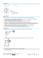
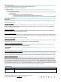
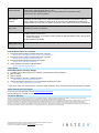
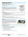
Quick Start Guide
INSTEON® Motion Sensor
Models: 2842-222, 2842-422, 2842-522
Tools Needed
•
Small Phillips screwdriver
LED
Introduction
The INSTEON Motion Sensor is an indoor/outdoor motion sensor that will turn
INSTEON-controlled lights on and off in response to movement around your
home. The sensor also contains a photocell, allowing you to configure the unit to
only turn your lights on at night. Pair the Motion Sensor with INSTEON software for
almost limitless automation possibilities.
In this package you will find the Motion Sensor, a 9V battery, a swivel mount and 2
screws.
Operation
When Motion is Sensed
1)
When motion is sensed the Motion Sensor will send an ON command to up to 30 linked INSTEON responders and flash its
LED (unless it is daytime and unit is in night-only mode)
2)
Sensor will begin its automatic countdown
3)
Whenever motion is sensed during countdown, the countdown will be reset to easily allow you to create “occupied” versus
“unoccupied” modes for your home
4)
When countdown expires the Sensor will send an OFF command to all linked responders (unless it is in on-only mode)
Applications
•
Turn on driveway or front step lights when visitors approach
•
Have your fountain always on when you are around (and off when you are away)
•
Save money by having HVAC and lighting automatically go into energy-saving mode when no one is around
Setup
Insert Battery
Use a small Phillips screwdriver to remove screw and cover from battery
compartment on back of unit. Attach the included 9V battery. Do not replace
compartment cover until instructed to do so later in this manual. Wait 5 minutes
for the circuit to stabilize. Then, to confirm unit is functioning, tap the Set button
a couple of times while watching the front of the unit. Each time you tap the Set
button, a red LED behind the sensor lens will flash. Don’t worry if the LED
flashes when you are not tapping the Set button; it is simply indicating that
motion is being detected.
Set button
Close-up of battery compartment
Dual-Band Products and Access Points
If you want Motion Sensor to control a powerline-only device, you need at least one INSTEON Access Point (#2443) or other dualband product installed in your home.
Make Motion Sensor a Controller
1)
2)
3)
4)
5)
Press and hold the set button on Motion Sensor for 5 seconds
Motion Sensor LED (behind sensor lens) will start blinking red
Turn responder on (or any other state such as on 50% or even off)
Press and hold responder set button until it double-beeps
Motion Sensor LED will stop blinking
Test by tapping Motion Sensor set button
Responder load will respond appropriately
Motion Sensor LED will blink red
Repeat steps 1-4 for up to 32 responders you wish Motion Sensor to control
2452-222/2452-422/2452-522 Rev. 11/6/2012 1:27 PM / See Owner’s Manual for Warranty Information.
Protected under U.S. and foreign patents (see www.insteon.com)
© Copyright 2012 INSTEON, 16542 Millikan Ave., Irvine, CA 92606, 800-762-7845
Detecting Area
Placement Tips
Select a location that will provide the coverage required while keeping in mind the following potential problems:
•
•
•
•
•
•
•
•
•
Reflective surfaces - Do not aim the detector at reflective surfaces such as mirrors or windows as this may distort the
coverage pattern or reflect sunlight directly onto the detector
Air flow - Avoid locations that are subject to direct high air flow such as near an air duct outlet
Moisture - Do not place the detector near sources of steam or oil
Sunlight - Do not aim the detector such that it will receive direct or reflected (mirror) sunlight
Obstruction - Do not limit the coverage with large objects within the detection area such as plants or filing cabinets
Pet rejection - Do not aim the detector at a stairway which a pet has access to and do not place furniture or objects higher
than 3 ft./0.9 m, which a pet can climb onto (e.g. a cat on a couch), closer than 6 ft./1.8 m to the detector
Fireplace - Do not place the detector near a fireplace due to the light and heat
Snow or ice – Snow or ice on the Fresnel lens may interfere with Motion Sensor’s ability to detect motion
Dirt – Dirt on the Fresnel lens may interfere with Motion Sensor’s ability to detect motion
Mount Sensor
1) Use the two small screws (included) to secure the swivel mounting bracket at your desired location
2) Slide Motion Sensor onto the swivel mounting bracket (sliding the unit to the right) until you hear a click
3) Aim Motion Sensor towards the area in which you wish to detect motion
4) Test by walking through the area. Responder(s) should respond appropriately when motion is sensed and turn off 30 seconds
after last motion sensed.
2452-222/2452-422/2452-522 Rev. 11/6/2012 1:27 PM / See Owner’s Manual for Warranty Information.
Protected under U.S. and foreign patents (see www.insteon.com)
© Copyright 2012 INSTEON, 16542 Millikan Ave., Irvine, CA 92606, 800-762-7845
Adjust Detection Area
1) Tap the Set button on Motion Sensor until the linked responder(s) turn off
2) Within 10 seconds walk well out of detection area
3) Wait 20 seconds
4) Walk into and near your detection area. Your linked responders will turn on (LED will flash upon initial motion, then once
every 8 seconds during motion).
a. If LED does not flash while you are moving within the desired detection area, re-aim sensor (usually means pointing
the Sensor “up”)
b. If LED flashes while you’re moving outside detection area:
i. Aim sensor to decrease range (usually means aiming the sensor “down”).
ii. If aiming sensor does not generate desired results place jumper 1 on both pins (see section Setup Modes).
Setup Modes (Optional)
Set Jumpers
Jumpers are small plastic “boxes” that act as a switch. When installed on 2 pins, the switch is “on.” When installed on 1 pin (or
missing), the switch is “off.”
Jumper 1 – Sensitivity
To reduce sensor’s detection range by approximately 33%, use needle-nose pliers to carefully remove Jumper 1 (the left-most
jumper) from the single pin it is installed on and reinstall it on both pins. Tap the set button once, wait 10 seconds and activate
motion to establish the new setting.
Jumper 2 – Disable LED
If you wish to disable the LED (it will still operate during setup), install Jumper 2 on both pins. Tap the set button once, wait 10
seconds and activate motion to establish the new setting.
Jumper 3 – Night-Only Mode
If you wish to have the Sensor operate only when dark, install Jumper 3 on both pins. Tap the Set button once, wait 10 seconds
and activate motion to establish the new setting. Note: It takes 3.5 minutes (or 7 Set button taps) to detect the difference between
day and night. See Day/Night Threshold below for details.
Jumper 4 – On-Only Mode
If you wish to disable the automatic-off countdown, install jumper 4 on both pins and the Motion Sensor will only send “On.” Tap
the Set button once, wait 10 seconds, and activate motion to establish the new setting.
Jumper 5 – Remote (Software) Management
If you wish to manage all of sensors settings via INSTEON software (such as HouseLinc), install jumper 5 on both pins. Then,
follow your INSTEON software instructions for managing sensor.
Adjust Modes
Adjust Dials
Left Dial – Adjust Automatic “Off” Countdown
Using a small Phillips screwdriver, adjust to the desired time duration in which you want Motion Sensor to send an OFF command
after the last motion sensed. Turning the dial all the way counter-clockwise sets the countdown to 30 seconds; turning the dial all
the way clockwise sets it to 2 hours. Anywhere in between results in a proportional difference between 30 seconds and 2 hours.
Right Dial – Day/Night Threshold
Using a small Phillips screwdriver, adjust the day/night threshold to desired light level. Turning the dial clockwise increases the
light level of the threshold; turning the dial counter-clockwise decreases the light level of the threshold. For example, when you
turn the dial all the way clockwise, Motion Sensor will read “night” no matter how bright it is. Likewise, turning the dial all the way
counter-clockwise will make Motion Sensor read “day” no matter how dark it is. Turning the dial anywhere in between will choose
the specific light level which Motion Sensor uses to determine “night” vs. “day.” To test, set Motion Sensor to night-only mode (see
above) and tap the set button 7 times. If it reads the current light level as “night,” it will turn on its linked responders on first sensed
motion. If it reads “day,” the LED will flash on first motion, but it will not turn on its linked responders.
Troubleshooting
Symptom
Sensor won’t link to
responders
Resolution
Move a dual-band INSTEON device (e.g., Access Point) closer to the Motion Sensor
2452-222/2452-422/2452-522 Rev. 11/6/2012 1:27 PM / See Owner’s Manual for Warranty Information.
Protected under U.S. and foreign patents (see www.insteon.com)
© Copyright 2012 INSTEON, 16542 Millikan Ave., Irvine, CA 92606, 800-762-7845
Sensor won’t control
linked responders
a) Make sure LED flashes to confirm it has power and is sensing motion
b) Sensor is in night-only mode (and it is “day”)
c) Move a dual-band INSTEON device (e.g., Access Point) closer to the Motion Sensor
d) Sensor is in its 1 minute countdown
LED flashing rapidly
after motion is
detected
Sensor did not receive an acknowledgement from one or more linked devices. If this occurs
repeatedly you may need to move a dual-band INSTEON device closer to the Sensor or you may
need to unlink a device which is no longer in use in your home. If the INSTEON responders are no
longer available, you may either use software or perform a factory reset to remove the unwanted links.
LED not flashing
upon motion
a) You may need to wait up to 8 seconds to see the flash
b) Battery may need to be replaced
Not sensing motion
a) Light detected and unit is in night-only mode
b) Motion Sensor aimed too low
c) Temperature too high, or low (sensor needs to be able to distinguish between what is being sensed
and its surroundings
d) See Placement Tips section
LED is double
flashing upon motion
Low battery warning—replace with fresh battery
Remove Motion Sensor as a Controller
1)
2)
3)
4)
Press and hold the set button on Motion Sensor for 5 seconds
Motion Sensor LED (behind sensor lens) will start blinking red
Press and hold the set button on Motion Sensor for 5 seconds
Motion Sensor LED will continue blinking red
Press and hold the responder set button until it beeps
Motion Sensor LED will stop blinking
Test by tapping the set button on Motion Sensor
Former responder will not respond
Factory Reset
Return Motion Sensor to Factory Settings
1) If possible, remove Motion Sensor as a controller of all responders before proceeding*
2) Remove battery
3) Wait 15 seconds
4) While pressing the set button, reattach the battery
After about 2 seconds the LED will turn on
5) Continue pressing the set button for 5 seconds and then release the set button.
The LED will turn off after about 2 seconds
* If you do not unlink, your responder will to continue to respond to Motion Sensor even after factory reset procedure is complete.
Owner’s Manual and Tech Support
For the most up-to-date Quick Start Guide visit http://www.insteon.com/support
Call: INSTEON Support Line at 866-243-8022
FCC and IC Warnings
This device complies with FCC Rules and Industry Canada license-exempt RSS standard(s). Operation is subject to the following two conditions: (1) this device may not cause harmful
interference, and (2) this device must accept any interference, including interference that may cause undesired operation of the device.
Le present appareil est conforme aux CNR d'Industrie Canada applicables aux appareils radio exempts de licence. L'exploitation est autorise aux deux conditions suivantes: (1) l'appareil ne doit
pas produire de brouillage, et (2) l'utilisateur de l'appareil doit accepter tout brouillage radiolectrique subi, mme si le brouillage est susceptible d'en compromettre le fonctionnement.
CAUTION - To reduce the risk of overheating and possible damage to other equipment do not install to control a receptacle, a motor-operated appliance, a fluorescent lighting fixture, or a
transformer-supplied appliance. Gradateurs commandant une lampe a filament de tungstene – afin de reduire le risqué de surchauffe et la possibilite d’endommagement a d’autres materiels, ne
pas installer pour commader une prise, un appareil a moteur, une lampe fluorescente ou un appareil alimente par un transformateur.
2452-222/2452-422/2452-522 Rev. 11/6/2012 1:27 PM / See Owner’s Manual for Warranty Information.
Protected under U.S. and foreign patents (see www.insteon.com)
© Copyright 2012 INSTEON, 16542 Millikan Ave., Irvine, CA 92606, 800-762-7845