1
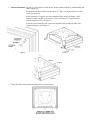
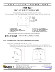
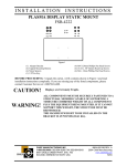
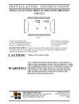
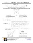
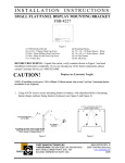
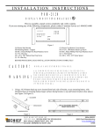
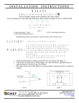
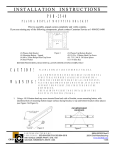
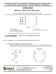
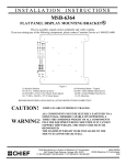
INSTALLATION
INSTRUCTIONS
FSB-4239
DISPLAY MOUNTING BRACKET
Prior to assembly, unpack carton completely and verify contents.
If you are missing any of the following components, please contact Customer Service at 1-800/582-6480
(1) Interface Bracket
(4) Mounting Buttons – Tapped
(2) ¼-20 Phillips Pan Head Screws
(2) M4 Acorn Nuts
(1) 1/8" Hex Key
Figure 1
(4) .625 x .194 x .125 Nylon Spacers
(4) 10-24 x .500 Button Head Cap Screws
(2) .687 x .260 x .062 Nylon Spacers
(2) M3 x 16mm Philips Flat Head Screws
(2) M4 x 12mm Philips Pan Head Screws
BEFORE PROCEEDING, READ INSTALLATION INSTRUCTIONS COMPLETELY
CAUTION!
DISPLAYS ARE EXTREMELY FRAGILE.
NOTE: If installing screen on a Chief F-series swing arm mount, proceed to Step 2.
1.
Chief Q2 Button Installation (Used with FSM, FPM, FSP, FDP mounts):
Using a 10-24 button head cap screw inserted from back side of bracket, secure mounting button, with
chamfered hole of mounting button (larger surface) facing bracket (four places) (see Figure 2 & Figure3).
Figure 2
CHIEF MANUFACTURING INC.
1-800-582-6480 952-894-6280 FAX 952-894-6918
8401 EAGLE CREEK PKWY, STE. 700
SAVAGE, MINNESOTA 55378 USA
Figure 3
8835-000003 Rev01
2006 Chief Manufacturing
www.chiefmfg.com
07/06
2. Bracket Installation: Lay the TV screen down on a flat surface. Remove table stand brace, antenna holder and
rubber tipped feet.
Insert M4 screws into keyhole slots in back of TV. Place 1/8" nylon washers over M4
screws (see Figure 4).
Place remaining 1/8" spacers over table stand brace holes in back of display. Place
interface bracket over M4 screws and use ¼-20 screws and .063" spacers to secure
bracket to bottom of TV (see Figure 5).
Insert M3 screws and acorn nuts. M4 screws should be fully seated in keyhole slots.
Tighten all fasteners (See Figure 6).
Figure 4
Figure 5
Figure 6
3. Follow the Chief mount instruction manual for screen installation.