1
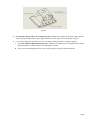
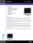
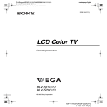
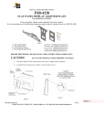
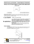
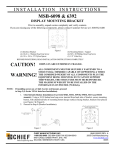
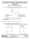
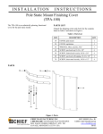
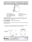
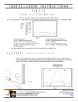
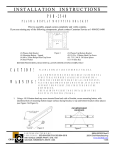
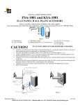
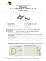
INSTALLATION INSTRUCTIONS
FSB-4236
FLAT PANEL DISPLAY ADAPTER PLATE
For SONY KLV S15G10
Prior to assembly, unpack carton completely and verify contents.
If you are missing any of the following components, please contact Customer Service at 1-800/582-6480.
Figure 1
(1)
(1)
(4)
(4)
Base Adapter Bracket
VESA Interface Bracket
Mounting Buttons
M4 x 6mm Phillips Pan Head Screws
(4) 10-24 x 1/2” Button Head Cap Screws
(4) ¼-20 x 3/8” Button Head Cap Screws
(4) M4 Flat Washers
(1) 5/32” Hex Key
(1) 1/8” Hex Key
BEFORE PROCEEDING, READ INSTALLATION INSTRUCTIONS COMPLETELY
CAUTION!
1.
FLAT PANEL DISPLAYS ARE EXTREMELY FRAGILE.
Using a Phillips head screwdriver, remove Sony’s table stand from display.
**Important** Keep the four Phillips pan head screws removed with the table stand! They will be used in the
interface assembly.
2.
Assemble Brackets: Attach base adapter bracket to VESA interface bracket using four ¼-20 x 3/8” Phillips pan
head screws. (see Figure 2).
NOTE: If installing screen onto a VESA 100mm X 100mm mount skip to step 4 (mounting button installation
is not required).
3.
Mounting Button Installation: Install four Mounting Buttons using four #10-24 x 1/2” Phillips pan head screws
(see Figure 3).
4.
Assemble bracket to display: Attach assembled bracket to display using four M4 washers and the four M4 screws
removed earlier from the display. (see Figure 4).
Figure 2
Figure 3
8804-000300 Rev B
CHIEF MANUFACTURING INC. 1-800-582-6480, Fax: 1-877-894-6918, Email: [email protected]
10/16/06
Figure 4
5.
For Chief Q2™ mounts with 5” X 5” Mounting System - With the aid of another person, lift the display up to the
mount, align the mounting buttons on the display with the slots in the mount, and set the display into place.
6.
Lower safety latch on the Chief Mount to secure your display, making sure latch is completely engaged.
7.
For VESA 100mm X 100mm Mounting Systems - With the aid of another person, lift display up to the mount,
align threaded holes of interface bracket to mounting holes of mount.
8.
Using four M4 x 6mm Phillips pan head screws, attach display to mount (per mount instructions).
Page 2