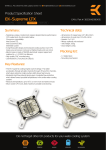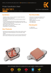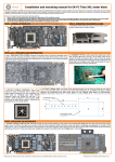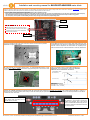
1
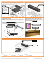
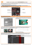
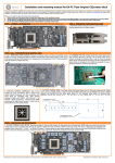
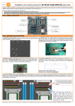
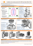
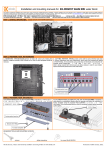
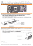
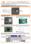
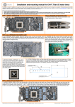
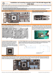
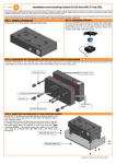
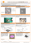
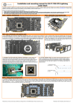
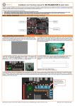
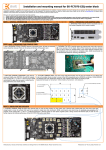
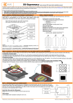
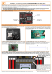
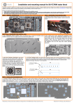
Installation and mounting manual for EK-FB KIT ASUS R5E water block:
This product is intended for installation only by expert users. Please consult with a qualified technician for installation. Improper installation may result in damage to your equipment. EK Water Blocks assumes no liability
whatsoever, expressed or implied, for the use of these products, nor their installation. The following instructions are subject to change without notice. Please visit our web site at www.ekwb.com for updates. Before
installation of this product please read important notice, disclosure and warranty conditions printed on the back of the box.
Before you start using this product please follow these basic guidelines:
1. Please carefully read the manual before through before beginning with the installation process!
2. Please remove your motherboard from the computer to assure safest mounting process in order to prevent any possible damages to your CPU and/or motherboard’s circuit board (PCB).
3. The EK High Flow and EK-CSQ type fittings require only a small amount of force to screw them firmly in place since the liquid seal is ensured by the rubber O-ring gaskets.
4. The use of quality, market proved corrosion inhibiting coolants is always strongly recommended for any liquid cooling system.
STEP 1: GENERAL INFORMATION Sample photo of ASUS Rampage V Extreme edition motherboard
Mosfets
IMPORTANT NOTICE:
CPU socket
ROG LED (Logo) has to be removed in order to
successfully complete installation of the FB KIT
ASUS R5E and cannot be used in combination
with the FB KIT ASUS R5E.
X99 PCH (SB)
STEP 2: PREPARING YOUR MOTHERBOARD
1. REMOVING STOCK COOLER. Remove all encircled screws. There are 13 screws on the
back of the motherboard that needs to be removed in order to remove the factory installed
SB/MOSFET heat pipe cooling solution.
2. CLEANING THE PCB. Carefully detach the original stock cooler after
removing all screws securing it to the board. Wipe off the remains (by using
non–abrasive cloth or qtip, as shown on sample photo) of the original thermal
compound until the components and circuit board are completely clean.
EKWB recommends the use of denatured alcohol for removing TIM leftovers.
3. APPLYING THERMAL COMPOUND. Apply thermal compound: lightly coat the Intel X99 PCH 4. CUTTING THERMAL PADS. Your block comes with thermal pads which
(SB) with electrically non-conductive thermal grease - for example Gelid GC-Extreme™, Arctic
Cooling MX-2™- or MX-4™. EKWB recommends to apply thermal grease in cross form for best
performance (see sample picture).
needs to be trimmed in order to fit the voltage regulation area
(VRM/MOSFET) on the motherboard’s circuit board. WARNING:
DIMENSIONS ON PICTURES BELOW ARE SCALED.
1: Thermal pad A – 0.5mm
(for VRM/MOSFET):
2: Thermal pad A – 1.0mm
(for inductor coils):
Replacement thermal pads @
EKWB web shop:
Thermal PAD A 1mm - (100x16mm) [EAN: 3830046996626]
Thermal PAD A 0.5mm - (100x16mm) [EAN: 3830046996619]
5. PLACING THERMAL PADS ON MOTHERBOARD. Place thermal pads you cut on PCB as shown on picture bellow (PLEASE REMOVE THE PROTECTIVE FOIL FROM BOTH
SIDES OF THE THERMAL PADS PRIOR TO INSTALLATION). EK recommends using small drops of electrically non-conductive (for example: Arctic Cooling MX-2 ™ or MX-4 ™)
thermal grease on each phase regulator (that is being covered with thermal pad; see picture below) in order to even further improve the thermal performance of the EK-FB
KIT ASUS R5E series water block.
Place 0.5mm thermal pads in larger strips
over marked area and make sure all
mosfet chips are covered.
All disclosures, notices and warranty conditions are being written on EKWB web page. Please check terms of use.
Place 1mm thermal pads in larger strips over the
coils (inductors). This is merely to prevent any
possible short circuiting. Due to the uneven
nature of motherboard manufacturing not all of
the inductors will have contact with the thermal
pad. This is normal.
Published on October 27th 2014
STEP 3: PREPARING YOUR WATER BLOCK
1. PLACING SB BLOCK ON MOTHERBOARD. Place the SB part of the water block with
preinstalled 2.5mm standoffs kit gently to the motherboard or vice versa. Make sure that
mounting holes are aligned. Skip to STEP 4 on how to fasten the water block to the
motherboard using the enclosed screws and washers.
2. PLACING MOSFET BLOCK ON MOTHERBOARD. Place the water block
gently to the motherboard or vice versa. Make sure that mounting holes are
aligned.
MOSFET block
SB block
You can use a bit of
themal paste to
»glue« the PVC
washers on the
standoffs for easier
installation of the
waterblock.
STEP 4: ATTACHING BLOCK TO MOTHERBOARD
STEP 5: CHECKING FOR CONTACTS
Prior to fastening the screws please make sure the mounting holes on the motherboard’s circuit
board are aligned with the water block.
Temporarily remove the water block to check for uniform surface contact
between the block and the components. Then repeat steps 3 and 4 to
reattach the block applying more or less pressure to the areas where you
have found it necessary. Note that there is no need for perfect thermal pad
imprint on the inductors/coils (mentioned in STEP2)
A) SB block: Use five M3x5 DIN7985 and washers. Tighten the screws, beginning near the
south bridge, and continue evenly outwards. Do not use excessive force when tightening the
screws!
B) MOSFET block: Use ASUS factory (“stock”) backplate and two M3x8 DIN7991 screws. Use
2mm allen key to tighten the screws. Do not use excessive force when tightening the screws!
Use the enclosed screws and washers as shown in picture below:
Chip die thermal grease imprint
M3x8 DIN 7991 screw
ASUS Factory backplate
Thermal pad imprints
M3x5 DIN 7985 screw
PVC washer
6. POSITIONING FITTINGS AND CONNECTING TO WATER CIRCUIT
Attach the liquid cooling tubes and connect the water-block(s) into the cooling circuit. EKWB recommends using EK-CSQ compression fittings with the EK-FB KIT ASUS R5E
series water block. You can use any opening as an inlet/outlet port. Plan your tubing routing in advance!
Tubing
EK-CSQ fitting
REQUIRED TOOLS:
scissors
philips screwdriver
thermal grease
All disclosures, notices and warranty conditions are being written on EKWB web page. Please check terms of use.
2mm Allen key
Published on October 27th 2014