1
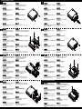
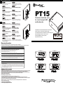
VESA mount installation procedure
2
Secure VESA mount bracket with four
screws on rear of monitor.
С помощью четырех винтов закрепите
монтажный кронштейн VESA на задней
панели монитора.
VESA-Montagehalterung mit vier
將VESA背板以四顆螺絲鎖固於螢幕後方。
Schrauben an der Rückseite des Monitors
befestigen.
Vissez la console de montage VESA avec 将VESA背板以四颗螺丝锁固于屏幕后方。
les quatre vis à l'arrière de l'écran.
3
Fije el bracket de la montura VESA con
cuatro tornillos a la parte trasera del
monitor.
VESAマウントブラケットをモニタ後部
にネジ4本で固定します。
Fissare il supporto VESA con quattro viti
alla parte posteriore del monitor.
네 개의 나사를 사용하여 VESA 장착
브래킷을 모니터의 후면에 고정합니다.
PT15
Premium aluminum case
for Intel Haswell NUC
motherboards
Выровняйте и установите PT15 в
Align and push PT15 into the VESA
bracket, than push downward to complete кронштейн VESA, затем нажмите
вниз для окончательной установки.
installation.
PT15 an der VESA-Halterung ausrichten
und drücken; dann zum Abschließen der
Installation nach unten drücken.
先將PT15對齊VESA背板後推入,
再往下扣住背板即可完成安裝。
Alignez et poussez le PT15 dans la
console VESA, puis poussez vers le bas
pour terminer l'installation.
先将PT15对齐VESA背板后推入,
再往下扣住背板即可完成安装。
Alinee y presione la PT15 contra el bracket PT15をVESAブラケットに合わせて押
VESA, luego presione hacia abajo para
さえ、下方に押して装着は完了です。
completar la instalación.
Compatible with most Intel Haswell-based NUC motherboards
Premium aluminum construction & SilverStone styling
Pre-assembled WIFI antenna and Bluetooth for ease of deployment
Super small design at 130mm x 110mm x 41mm
Includes VESA MISD-75 mounting bracket
Supports DIN rail mounting
NUC
NEXT UNIT OF COMPUTING
Allineare e spingere PT15 ne supporto
VESA, quindi spingere verso il basso per
completare l'installazione.
PT15를 VESA 브래킷에 맞춰 정렬하여
밀어 넣은 후 아래로 눌러 설치를 완료합니다.
Warranty Information
This product has a limited 3 year warranty in North America, Europe, and Australia.
For information on warranty periods in other regions, please contact your reseller or SilverStone authorized distributor.
Warranty terms & conditions
1. Product component defects or damages resulted from defective production is covered under warranty.
Defects or damages with the following conditions will be fixed or replaced under SilverStone Technology’s jurisdiction.
a) Usage in accordance with instructions provided in this manual, with no misuse, overuse, or other inappropriate actions.
b) Damage not caused by natural disaster (thunder, fire, earthquake, flood, salt, wind, insect, animals, etc…)
c) Product is not disassembled, modified, or fixed. Components not disassembled or replaced.
d) Warranty mark/stickers are not removed or broken.
Loss or damages resulted from conditions other than ones listed above are not covered under warranty.
2. Under warranty, SilverStone Technology’s maximum liability is limited to the current market value for the product (depreciated value, excluding
shipping, handling, and other fees). SilverStone Technology is not responsible for other damages or loss associated with the use of product.
3. Under warranty, SilverStone Technology is obligated to repair or replace its defective products. Under no circumstances will SilverStone
Technology be liable for damages in connection with the sale, purchase, or use including but not limited to loss of data, loss of business, loss of
profits, loss of use of the product or incidental or consequential damage whether or not foreseeable and whether or not based on breach of warranty,
contract or negligence, even if SilverStone Technology has been advised of the possibility of such damages.
4. Warranty covers only the original purchaser through authorized SilverStone distributors and resellers and is not transferable to a second hand
purchaser.
5. You must provide sales receipt or invoice with clear indication of purchase date to determine warranty eligibility.
6. If a problem develops during the warranty period, please contact your retailer/reseller/SilverStone authorized distributors or SilverStone
http://www.silverstonetek.com.
Please note that: (i) You must provide proof of original purchase of the product by a dated itemized receipt; (ii) You shall bear the cost of shipping
(or otherwise transporting) the product to SilverStone authorized distributors. SilverStone authorized distributors will bear the cost of shipping
(or otherwise transporting) the product back to you after completing the warranty service; (iii) Before you send the product, you must be issued a
Return Merchandise Authorization (“RMA”) number from SilverStone. Updated warranty information will be posted on SilverStone’s official website.
Please visit http://www.silverstonetek.com for the latest updates.
Additional info & contacts
For North America ([email protected])
SilverStone Technology in North America may repair or replace defective product with refurbished product that is not new but has been functionally tested.
Replacement product will be warranted for remainder of the warranty period or thirty days, whichever is longer. All products should be sent
back to the place of purchase if it is within 30 days of purchase, after 30 days, customers need to initiate RMA procedure with SilverStone Technology
in USA by first downloading the “USA RMA form for end-users” form from the below link and follow its instructions.
http://silverstonetek.com/contactus.php
For Australia only ([email protected])
Our goods come with guarantees that cannot be excluded under the Australian Consumer Law.
You are entitled to a replacement or refund for a major failure and for compensation for any other reasonably foreseeable loss or damage.
You are also entitled to have the goods repaired or replaced if the goods fail to be of acceptable quality and the failure does not amount to a major failure.
Please refer to above “Warranty terms & conditions” for further warranty details.
SilverStone Technology Co., Ltd. 12F No. 168 Jiankang Rd., Zhonghe Dist., New Taipei City 235 Taiwan R.O.C. + 886-2-8228-1238
(standard international call charges apply)
For Europe ([email protected])
For all other regions ([email protected])
2014
NO.G11221090
Motherboard installation procedure
1
2
3
Loosen two screws from the front
and rear of PT15
Отверните два винта на передней
и задней панели корпуса PT15
Zwei Schrauben an der Vorder- und
Rückseite des PT15 lösen.
5
Insert the installed bottom tray back into
the case.
Установите нижний лоток на
место в корпус.
將PT15後背板兩顆平頭螺絲卸除。
Installiertes unteres Fach wieder in das
Gehäuse einsetzen.
將組裝好的底板滑入機殼內。
Dévissez les deux vis à l'avant et à
l'arrière du PT15
将PT15后背板两颗平头螺丝卸除。
Replacez le plateau inférieur dans le
boîtier.
将组装好的底板滑入机壳内。
Afloje dos tornillos de la parte frontal
y trasera de la PT15
PT15の前部と後部からネジ2本を外
します。
Inserte la bandeja inferior instalada de
vuelta en la carcasa.
取り付けられたマザーボードをケ
ースに戻します。
Allentare le due viti dal pannello anteriore
e posteriore di PT15.
PT15의 전면과 후면에서 2개의 나사를
풉니다.
Inserire nel telaio il cassetto inferiore con
la scheda madre installata.
설치된 하단 트레이를 케이스에
도로 끼웁니다.
Loosen four screws and foot stands
from the bottom of PT15 then pull out
the bottom tray.
Отверните четыре винта и стойки с нижней
части корпуса PT15 и извлеките нижний лоток.
Secure two screws back to the rear
of the case.
Заверните два винта на задней
панели корпуса.
Vier Schrauben und Fußständer von der
Unterseite des PT15 lösen, dann unteres
Fach herausziehen.
將底部四顆螺絲與腳墊卸除,並將底板抽出。
Zwei Schrauben wieder an der Rückseite
des Gehäuses befestigen.
鎖上後面板與兩顆平頭螺絲
Dévissez les quatre vis et les supports
将底部四颗螺丝与脚垫卸除,并将底板抽出。
de pieds en dessous du PT15, puis retirez
le plateau inférieur.
Vissez de nouveau les deux vis à l'arrière
du boîtier.
锁上后面板与两颗平头螺丝
Afloje cuatro tornillos y soportes de la
parte inferior de la PT15, luego tire de la
bandeja inferior.
PT15の底部からネジ4本とフットスタンド
4個を外してから、底部トレイを引き出し
ます。
Fije de nuevo dos tornillos en la parte
trasera de la carcasa.
ケースにネジ2本を戻します。
Allentare le quattro viti ed i piedini dal
pannello inferiore di PT15, quindi estrarre
il cassetto inferiore.
4개의 나사를 풀어 PT15의 하단에서 바닥
받침대를 제거한 후 하단 트레이를 빼냅니다.
Fissare di nuovo le due viti sul pannello
posteriore del telaio.
2개의 나사를 케이스의 후면에
도로 고정합니다.
Connect WiFi antenna cable to the WiFi
module at this point if the motherboard
supports it.
Подключите кабель антенны WiFi к
модулю WiFi, если системная плата
поддерживает эту функцию.
Secure four screws and foot stands back
to the bottom of PT15.
Заверните четыре винта и стойки
в нижней части корпуса PT15
An diesem Punkt WLAN-Antennenkabel
an WLAN-Modul anschließen, falls das
Motherboard dies unterstützt.
若有無線網卡,需先接上天線導線。
Vier Schrauben und Fußständer wieder
an der Unterseite des PT15 befestigen.
將四顆螺絲與腳墊裝回PT15
Branchez ensuite le câble de l'antenne
Wi-Fi sur le module Wi-Fi si la carte mère
le prend en charge.
若有无线网卡,需先接上天线导线。
Vissez les quatre vis et les supports de
pieds en dessous du PT15.
将四颗螺丝与脚垫装回PT15
Conecte el cable de antena WiFi al
módulo WiFi en este momento si la
placa base lo soporta.
マザーボードがWiFi対応であれば、
この時点でWiFiアンテナケーブルを
WiFiモジュールに接続します。
Fije cuatro tornillos y los soportes de
nuevo en la parte inferior de la PT15.
PT15の底部に4個のフットスタン
ドとネジ4本を戻します。
A questo punto, collegare il cavo
dell'antenna WiFi al modulo WiFi, se la
scheda madre lo supporta.
이 때 메인보드가 WiFi 모듈을 지원하는
경우 WiFi 안테나 케이블을 WiFi 모듈에
연결합니다.
Fissare di nuovo le quattro viti ed i piedini
sul pannello inferiore di PT15.
4개의 나사를 사용하여 PT15의
하단에 바닥 받침대를 도로
고정합니다.
Install motherboard onto the bottom tray
and secure it with four screws.
Установите системную плату в нижний
лоток и закрепите ее четырьмя винтами.
6
7
VESA mount installation procedure
4
Motherboard am unteren Fach installieren 將主機板用四顆螺絲鎖在底板上。
und mit vier Schrauben befestigen.
Installez la carte mère sur le plateau
inférieur, puis fixez-le avec quatre vis.
将主板用四颗螺丝锁在底板上。
Instale la placa base en la bandeja inferior マザーボードを底部トレイに取り付け、
y fíjela con cuatro tornillos.
ネジ4本で固定します。
Installare la scheda madre nel cassetto
inferiore e fissarla con quattro viti.
메인보드를 하단 트레이에 설치하고 4개의
나사를 사용하여 이를 고정합니다.
1
Secure anti-vibration rubber gasket
with two screws on the bottom of PT15.
С помощью двух винтов закрепите
антивибрационную резиновую прокладку
на нижней части корпуса PT15.
Vibrationsfeste Gummidichtung mit zwei
Schrauben an der Unterseite des PT15
anbringen.
將防震膠墊以兩顆螺絲鎖固於PT15底部。
Vissez la rondelle en caoutchouc antivibration avec les deux vis au bas du
PT15.
将防震胶垫以两颗螺丝锁固于PT15底部。
Fije la junta de goma anti vibración con
PT15底部に防振ゴムパッキングをネ
dos tornillos en la parte inferior de la PT15. ジ2本で固定します。
Fissare le guarnizioni di gomma anti두 개의 나사를 사용하여 진동 방지 고무
vibrazione con due viti sulla parte inferiore 가스켓을 PT15의 하단에 고정합니다.
di PT15.