1
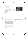
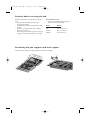
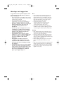
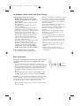
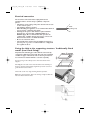
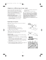
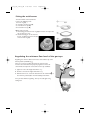
5019_719_01132_GB
1-06-2007
14:30
Pagina 1
KHPF 7510
KHPS 7510
Instructions for use
5019_719_01132_GB
1-06-2007
14:30
Pagina 2
5019_719_01132_GB
1-06-2007
14:30
Pagina 3
Product description and symbols
4
Using the burners
4
Practical advice on using the hob
5
Positioning the pan supports and wok support
5
Hood and cabinetry clearances (mm)
6
Injector table
6
Warnings and suggestions
7
Safeguarding the environment
8
Installation (Flush and Traditional fitting)
9
Gas connection
9
Electrical connection
10
Fixing the Hob to the supporting structure.
Traditionally fitted model (Semi Flush fitting).
10
Fixing the Hob to the worktop. Flush fitted model.
11
Adaption to a different type of gas supply
12
Replacing the injectors
12
Fitting the wok burner
13
Regulating the minimum flow level of the gas taps
13
General cleaning & maintenance
14
Care and maintenance of the gas burners
14
Troubleshooting guide
15
After Sales Service
15
5019_719_01132_GB
1-06-2007
14:30
Pagina 4
Product description and symbols
1.
2.
3.
4.
5.
6.
7.
8.
9.
Removable pan supports
1 kWh auxiliary burner
1.65 kWh semi-fast burner
1.65 kWh semi-fast burner
Professional wok burner
Auxiliary burner control knob
Semi-fast burner control knob
Semi-fast burner control knob
Professional wok burner control knob
Control Symbols
Off
Maximum flame
Minimum flame
Using the burners
If the burner goes out when the control knob
is released, the thermocouple did not engage.
wait al least 1 minute before repeating strps 1
to 3.
To turn on one of the burners:
1. Turn the corresponding control knob
anticlockwise until the indicator coincides with
the maximum flame symbol
.
2. Press the control knob to ignite the burner.
3. Once the burner has lit, keep the control knob
pressed for about 5 seconds to allow the safety
thermocouple fitted to each burner to engage.
The thermocouple will switch off the gas supply
to the burner should the flame be accidentally
lost ( A gust of air, momentary interruption of
gas supply or liquid spillage etc).
If the burner does not ignite within about 15
seconds, switch off the burner, check the
fitting of the burner cap and plate for correct
fitting. Wait at least 1 minute before trying
again.
4
5019_719_01132_GB
1-06-2007
14:30
Pagina 5
Practical advice on using the hob
Read the instructions to get the best out of your
hob.
• Use pans with a similar diameter to the
burner(see the table).
• Use flat bottomed pans except with the wok
support.
• Do not use excessive water when cooking
foods and use the lid.
• Ensure that pans are fully supported by the pan
supports and do not protrude over the edges.
You should never use:
• two burners simultaneously with just one
container such as a fish kettle.
Burner
Ø Pans
wok
semi fast
auxiliary
from 24 to 26 cm
from 16 to 24 cm
from 8 to 14 cm
Positioning the pan supports and wok support
Position the pan supports and wok support as indicated in the figure.
5
5019_719_01132_GB
1-06-2007
14:30
Pagina 6
Hood and cabinetry clearances (mm)
If a hood is to be installed above the hob, refer to the hood
installation instructions to ensure the correct height above
the hob.
Note: If the distance “A” between the kitchen wall cabinets is
between 600 and 730 mm, height “B" shall be at least 530
mm.
If the distance “A” between the kitchen wall cabinets is wider
than the hob’s width, height “B shall be at least 400 mm.
Injector table
Category II2H3+
Type of gas used
NATURAL GAS
(Methane) G20
LIQUID
PETROLEUM
GAS (Butane)
G30
LIQUID
PETROLEUM
GAS (Propane)
G31
Type of
burner
Injector
label
Control
primary air
(X) (mm)
Nominal
heat flow
kW
Nominal
Reduced
consumption heat flow
kW
min.
nom.
max.
wok
semi-fast
auxiliary
145
95
78
6
-
4,20
1,65
1,00
400 l/h
157 l/h
95 l/h
1,40
0,40
0,30
17
20
25
wok
semi-fast
auxiliary
100
65
50
11
-
4,20
1,65
1,00
305 g/h
120 g/h
73 g/h
1,40
0,40
0,30
20
28-30
35
wok
semi-fast
auxiliary
100
65
50
11
-
4,20
1,65
1,00
300 g/h
118 g/h
71 g/h
1,40
0,40
0,30
25
37
45
Gas pressure (mbar)
Type of gas used
Configuration model
Nominal heat flow kW
Overall nominal
consumption
Required air (m3) for
the combustion 1 m3 of
gas
G20 20 mbar
4 burners
8,5
809 l/h
9,52
G30 28-30 mbar
4 burners
8,5
618 g/h
30,94
G31 37 mbar
4 burners
8,5
607 g/h
23,80
Electric Power: 230 V - 50 Hz
6
5019_719_01132_GB
1-06-2007
14:30
Pagina 7
Warnings and suggestions
To get the most out of your hob, please read
the instructions carefully and keep them for
future consultation.
• These instructions are only valid in the countries
whose destination symbol is shown on the serial
number plate on the hob.
• The packing (plastic bags, expanded
polyurethane, etc) pose a potential threat to
children and should be disposed of carefully.
• Check the appliance has not been damaged
during transportation and remove all
protective packing and films before
installation.
• This hob (cat. 3) was designed to be used
exclusively for cooking food in household
surroundings. Any other use (for example
heating rooms) should be regarded as
improper and dangerous.
• The installation and connection of this
appliance to a gas or electrical supply must
be carried out by a competant, qualified
person in compliance with current
legislation.
• This appliance should be installed in
compliance with standards in force and
only used in well ventilated rooms. Read
the instructions before installing and using
this appliance.
• The pre-fitted gas connector and it's supply
pressure are shown on the label attached
to the bottom of the hob. If this type of gas
supply is not being used, please refer to
the section called Adaption to different
types of gas supply on page 11.
Note:
• Incorrect placement of the pan supports can
scratch the hob. To avoid this always ensure
that the rubber feet on the bottom of the pan
supports are the only part of the pan supports
that touch the hob and do not drag the pan
supports accross the hob surface.
• On the glass surface do not use:
- Cast iron grills, terracotta pots or pans.
- Heat convectors (e.g. metal netting).
- Using two burners to cook 1 pan.
• In the event of prolonged usage, additional
ventilation may be required (opening a window
or increasing the extration speed of the hood).
Warning
• Keep children away from the hob when in use
and don't let them play with the control knobs
or any other part of the appliance.
• Do not let children play with the pan supports.
The rubber feet on the underneath of the pan
supports could be swallowed by small and cause
serious injury or suffocation.
• Before replacing the pan supports on the hob,
please check that all the rubber feet are in
place.
• Each time you finish using the hob, always check
that the control buttons are in the off position
and shut off the tap to the gas mains or cylinder.
• Do not obstruct the air vents at the back of the
appliance in any way.
7
5019_719_01132_GB
1-06-2007
14:30
Pagina 8
Safeguarding the environment
Packing
The packing material is 100% recyclable and is
labelled with the recycling symbol
. Please
dispose of all packing responsibly and carefully.
Note:
• Incorrect placement of the pan supports can
scratch the hob. To avoid this always ensure
that the rubber feet on the bottom of the pan
supports are the only part of the pan supports
that touch the hob and do not drag the pan
supports across the hob surface.
• Do not use two burners to cook 1 pan.
• In the event of prolonged usage, additional
ventilation may be required (opening a window
or increasing the extraction speed of the hood).
Product
This appliance is marked according to the
European Directive 2002/96/EC, Waste Electrical
and Electronic Equipment (WEEE).
By ensuring that this product is disposed of
correctly, you will help prevent potentially negative
consequences for the environment and human
health.
Warning
• This appliance is not intended for use by
persons (including children) with reduced
physical, sensor or mental capabilities or lack of
experience and knowledge unless they have
been given initial supervision or instruction
concerning use of the applaince by a person
responsible for their safety.
• Keep children away from the hob when in
use and don't let them play with the
control knobs or any other part of the
appliance.
• Do not let children play with the pan
supports. The rubber feet on the
underneath of the pan supports could be
swallowed by small and cause serious injury
or suffocation.
• Before replacing the pan supports on the
hob, please check that all the rubber feet
are in place.
• Each time you finish using the hob, always
check that the control knobs are in the off
position and shut off the tap to the gas
mains or cylinder.
• Do not obstruct the air vents at the back
of the appliance in any way.
The symbol
on the product, or on the
documents accompanying this appliance indicates
that this product should not be disposed of as
household waste. Please dispose of this appliance
at an Electrical & Electronic Equipment Collection
point as in accordance with local environmental
regulations for waste disposal. For details of your
local Collection Point please contact your Local
Authority.
Conformity declaration
This hob was designed, built and marketed
incompliance with:
• the safety requirements in the “Gas” CEE
Directive 90/396
• the safety requirements of “Low Voltage
Directive” 2006/95/EC (replacing 73/23/EEC
and subsequent amendments)
• the protection requirements of the “EMC” CEE
Directive 89/336
• the requirements in CEE Directive 93/68
• this appliance was designed to come into
contact with foods and complies with EC
Regulation 1935/2004.
8
5019_719_01132_GB
1-06-2007
14:30
Pagina 9
Installation (Flush and Semi-Flush fitting)
Technical information for the installer
• Warning: this is a heavy products which
requires the installation to be carried out
by two people.
• When installing the hob it is advisable to wear
protective gloves.
• This appliance can be installed into a 20mm 50mm thick worktop.
• If no oven is to be installed below the hob, a
panel must be fitted under the hob to prevent
hob damage and protect the cupboard contents.
This panel must cover the whole of the
underside of the hob and must be positioned so
that an air gap of at least 50mm between the
panel and hob underside is maintained, as a
minimum, and as a maximum 150mm to the
underneath of the work surface.
• This hob is designed to operate perfectly with
any oven in the KitchenAid range. The
Manufacturer declines all responsibility should
any other make of oven be installed. The
manufacturer declines all responsibility
should another make of oven be installed.
calibration on the hob are compatible (see serial
number plate on the hob and the injector table).
• The cabinetry and appliances surrounding/next
to the hob are heat resistant and in compliance
with local regulations.
• The products of combustion are removed from
the atmosphere in the room by using an
extraction hood or electrical fan installed to the
walls and or windows, in line with current
regulations.
• The air circulates naturally through a suitable
opening that is no less than 100cm2 in cross
section, which must be:
- permanent and accessible on the walls of the
room being ventilated and extracting towards
the outside.
- created in such a way that the openings both
inside and out cannot be obstructed, even in
error.
- Protected by plastic grill, metallic netting etc.
that should not reduce the 100cm2 cross
section.
- Located in such a position so as not to
interfere with the extraction of the products
of combustion.
Before installation, please ensure that:
• The gas supply (type and pressure) and the
Gas connection
Connection to the mains gas system must be carried out by a
competant, registered person, in compliance with current
legislation.
• The connection of the hob to the gas mains network or gas
cylinder must be done using a rigid copper or steel pipe with parts
that comply with local standards, or using a flexible stainless steel
pipe with continuous surfaces that comply with local standards.
The flexible metallic pipe should be no longer than 2 linear
metres.
• Before connecting the pipe with the rubber part (A), insert the
seal (B) is in place (this part, provided complies with EN549).
Warning: if you use a stainless steel flexible pipe, it must be installed
in such a way that it does not come into contact with moving
cabinetry like drawers or kitchen cupboards and passes at a point
free of obstacles where it can be examined in its entirety.
• After connecting to the gas mains, use soap and water to check
there are no leaks.
9
5019_719_01132_GB
1-06-2007
14:30
Pagina 10
Electrical connection
The electrical connections must comply with current
legislation and be carried out by a qualified, competent
person.
• Information on the voltage and power absorbed are shown
on the serial no. plate.
• The appliance must be earthed.
• When installing the appliance, we recommend that this hob
is protected by a 3mm bi-polar switch.
• If damaged, the power cable must be replaced with an
identical type of powercable ( H05V2V2-FT90ºC, or
H05RR-F type). We recommend that this operation be
conducted by our After Sales Service. Please contact our
Customer Care Centre on 00800-3810-4026.
• Do not use extension cables.
• The manufacturer declines all responsibility for damage to
persons, pets or goods as a result of failure to comply with
the regulations above.
L
Earth
(yellow/green)
N
Fixing the Hob to the supporting structure. Traditionally fitted
model (Semi Flush fitting).
Important: The following procedure shall be carried out by
competent technical personnel only. The hob can be installed
on different types of materials, such as masonry, metal, bare
wood and heat resistant laminate coated wood (90°C).
Cut an opening in the worktop to the dimensions shown in the
diagram.
Carefully place the seal on the external outline of the worktop, as
shown in the figure below. Apply a light hand pressure to ensure a
good adhesion to the surface.
Fix the hob to the unit, using the fixing brackets provided.
Note: the electrical power cable must be long enough to allow the
hob to be lifted out from above.
10
5019_719_01132_GB
1-06-2007
14:30
Pagina 11
Fixing the Hob to the worktop. Flush fitted model.
Important: The following procedure shall
be carried out by competent technical
personnel only. The hob can be installed
on different types of materials, such as
masonry, metal, bare wood and heat
resistant laminate coated wood (90°C).
Cut an opening into the worktop to the
dimensions shown in the diagram. In order to
correctly fit this type of hob, a 3mm deep
recess around the edge of the opening is also
needed.
Fig. 1
Note: In case of laminated worktops with a laminate thickness lower
than 3 mm, create a recess as shown as on the detailed schematic
drawing.
Before positioning the hob, apply the adhesive seal supplied on the
bottom perimeter of the hob itself, where this will be in contact with
the worktop (fig. 2).
Once the seal is in position, place the hob in the recess. Fix the hob
to the worktop using the screws and brackets provided, tightening
them carefully until the hob is perfectly flush. (fig. 3).
Fig. 2
Carefully trim the excess seal. In case of installation on wood
(particularly chipboard), any small spaces between the edge of the
recess and the outside edge of the hob should be filled with small
quantities of silicon sealant (see fig. 4). Once the appliance has been
installed, the bottom part of the hob should be completely accessible.
Important:
• tighten the fixing brackets of the hob to the work top by hand,
using minimum force.
• In case of wooden (or similar) worktops, before fitting the
adhesive seal protect the surface of the milled recess with a
primer.
Fig. 3
Slots for extra brackets have been created on the bottom of the
appliance, to help achieve a more flush positioning (should this be
necessary). Appropriate brackets can be obtained from the Customer
Care Centre.
Fig. 4
11
5019_719_01132_GB
1-06-2007
14:30
Pagina 12
Adaption to a different type of gas supply
If you are using a different kind of gas from the one
indicated on the serial no. plate and the orange
label on the back of the hob, you must replace the
injectors; in the case of the Wok burner, adjust the
primary air (see Injector table on page 6).
The orange label should be removed and kept
together with the manual.
Use pressure regulators suitable for the gas
pressures indicated on page 6
• In order to replace the injectors, contact the
Customer Care Centre on 00800-3810-4026,
or a qualified electrician.
• Injectors not supplied as standard should be
requested from the Customer Care Centre on
00800-3810-4026.
• Regulate the minimum levels of the taps.
Note: with liquid petroleum gas ( G30/G31)
the bypass screw must be screwed in fully. If
you then experiance difficulty in turning the
control knob, contact our After sales Service
though our Customer Care Centre on
00800-3810-4026, who will arrange for a
replacement after ascertaining that the tap is
damaged.
Replacing the injectors
Note: Refer to the injector table to ensure the correct type of
injector is to be fitted.
Traditional burners (T)
1. Remove the pan supports (A).
2. Remove the burners (B).
3. Unscrew the injector (C) with a box spanner 7.
4. Replace the injector with the one for the new gas.
5. Replace burners and pan supports.
Note: Before installing the hob, please remember to stick the gas
calibration label, provided with the replacement injectors over the
gas information on the underside of the hob.
Wok Burner (W)
It is best to change the wok double crown burner before starting
installation. However it is necessary:
1. Lift out the hob from the work surface, removing the installation
fixing pieces.
2. Remove the screws securing the glass, at the back of the hob plate
and those located on both sides of the hob (E).
3. Remove the holding screws that fix the burner to the glass hob.
Once you have removed the glass hob, you can access the wok
burner injector.
4. Remove the injector (F) using a 10mm spanner.
5. Slacken the holding screw (H) to regulate the position (X) of the
gas inlet coupling (G) with regard to the injector.
12
5019_719_01132_GB
1-06-2007
14:30
Pagina 13
Fitting the wok burner
To fit the double crown wok burner:
Insert in the following order:
1. burner ring (A);
2. decorative covering ring (B);
3. external burner cap (C);
4. internal burner cap (D).
Note: make sure that:
1. the locating pin for the burner ring (A) is inserted correctly in the
slot on the burner unit.
2. that the locating pin on the external
burner cap (C) is inserted in the slot
on the burner ring (A).
Regulating the minimum flow level of the gas taps
Regulating the minimum flow level must be done with the tap at the
lowest position (small flame) .
There is no need to regulate the primary air in the burners.
To ensure the minimum level is properly regulated, remove the
control knob and adjust the screws found on the tap as follows:
1. tighten to reduce the height of the flame 1 (-)
2. slacken to increase the height of the flame (+);
3. With the burners on, rotate the buttons from the maximum
the minimum position to check the stability of the flame.
Once you have finished regulating, close up the seals again using
sealing wax.
13
to
5019_719_01132_GB
1-06-2007
14:30
Pagina 14
General cleaning & maintenance
Always disconnect the hob from the electrical
power supply and wait until it cools before cleaning
and/or doing maintenance work. n order to keep
your hob in good condition, you must keep it
clean, removing any remaining food each time you
use it. Cleaning the hob surface:
• the stainless steel surface may become stained if
it comes into contact with hard water over
along period of time or with extremely strong
cleaning products. Always clean any spillages as
quickly as possible (sauce, coffee, etc..). Wash
with lukewarm water and a mild detergent,
rinse and dry carefully with a soft cloth, or a
cloth designed to clean stainless steel. Only use
stainless steel cleaning products on the stainless
steel trim.
• Do not use harsh or corrosive products,
chloride based products or scourers.
• Do not steam clean.
• Do not use inflammable products.
• Do not leave acidic or alkaline based products
like vinegar, mustard, salt, sugar or lemon juice
lying on the hob, as this will damage the hob
and 'etch' the glass surface.
Note: With time, regular use of the hob could
cause some discolouration around the
burners. This is caused by the high
temperature of the flame and will not affect
the operation or performance of the hob.
Care and maintenance of the gas burners
The pan supports and burners can be removed to
make cleaning easier.
1. Hand wash carefully in hot water with a mild
detergent making sure that all the ingrained dirt
is removed and the openings on the burner are
not blocked. The internal burner cap (D), on
page 12 is made of brass and is subject to a
natural burnishing when it heats up. Clean it
each time you use it with a product specifically
designed for brass. Use hot water and a mild
deteregent to clean the the wok burner
external cap (item (C) on page 12). Never use
harsh products, or scourers that will damage
the special surface coverings.
2. Rinse and dry carefully.
3. Correctly refit the burners and caps in their place.
4. Make sure that when replacing the pan
supports, the pan support is located correctly
for each burner.
Note: Hobs fitted with electronic ignition and
thermocouples must have the ends of the igniters
and thermocouples cleaned regularly and
frequently in order to operate. Please clean them
very carefully with a damp cloth. Any remaining
ingrained food should be removed carefully with a
toothpick, or similar.
To avoid damaging the electronic ignition only
operate with the burners and pan supports
correctly in place.
14
5019_719_01132_GB
1-06-2007
14:30
Pagina 15
Troubleshooting guide
If the hob is not working properly, work through
this guide before contacting our Customer Care
Centre.
3. the end part of the thermocouple is clean.
The pans are not stable? Check that:
1. the bottom of the pan is perfectly flat.
2. the pan is centred on the burner.
3. the pan supports are correctly positioned with
all the rubber feet in place.
The burner does not ignite, or the flame is
unsteady? Check that:
1. the gas, or electricity supply has not been
interrupted and that the control knob is turned
fully on.
2. the gas supply has not run out.
3. the openings on the burner have become
blocked.
4. the end of the electronic igniter is clean.
5. all the parts on the burner are properly
positioned.
The flame doesn’t stay on? Check that:
1. the button was pushed in properly when turning
on the burner for the time required to activate
the safety thermocouple.
2. the burner's openings are not blocked near, or
around the thermocouple.
After Sales Service
• your name, full address including postcode and
telephone number.
Before contacting our Customer Care Centre
please check to see if the problem can be
fixed by refering to the troubleshooting guide.
1. If the fault persists contact us on 00800-38104026. We will ask you for some information, it
will help us, help you if you have the following
information ready to give us:
• a short description of the falut
• the serial number and model number of the
appliance
• the service number ( the number after the
word service on the rating plate on the bottom
of the hob. The service number can also be
found in the warranty booklet.
Note: If there is a problem with your hob,
failure to contact us could seriously
compromise the safety and quality of this
appliance.
15
5019_719_01132_GB
1-06-2007
14:30
Pagina 16
Whirlpool Europe S.r.l.
Viale G. Borghi, 27 - 21025 Comerio (VA)
Phone 0332.759111 - Fax 0332.759268
www.whirlpool.eu
Printed in Italy
06/07
5019 719 01132
n
GB