1
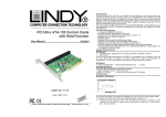
Raspberry Pi RF Transmitter
User Manual
Eng li sh
No. 84001
www.lindy.com
© LINDY ELECTRONICS LIMITED & LINDY-ELEKTRONIK GMBH - FIRST EDITION (September 2014)
User Manual
English
Introduction
Thank you for purchasing this RF controlled Raspberry Pi starter kit. Using this RF transmitter add on
board, you can control up to 4 radio controlled sockets from your Raspberry Pi.
The add-on board connects to the row of pins called the GPIO which can be controlled as either input or
output lines under the control of software.
We have written a simple program in Python to allow you to switch the remote controlled sockets on and
off with a single key press.
Package Contents
1 x RF transmitter add on board
2 x Radio Controlled Sockets
Features
Short range radio transmitter
Simple plug in installation
Up to 10 individual commands
Easy software control
Ideal learning and experimental tool
Compatible with 73113 (3 Pack Remote Control Sockets) & 73122 (4 Way Remote Controlled Strip)
Requirements
Raspberry Pi Version A or B
Installed OS: Raspian (or other LINUX OS with Python installed)
Installation
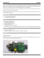
Installing the board
Install the board on to the row of pins as shown below and connect your Raspberry-Pi as normal to a
monitor, mouse, keyboard and USB power supply.
User Manual
English
The pin header connects to the add-on board as follows to allow you to control the GPIO lines as outputs
to drive the radio frequency transmitter.
Your software will use the outputs on the GPIO connector to drive the add-on board. We have written
some code in Python to switch the two sockets on and off.
Each board transmits a frame of information using On-Off-Keying (OOK) which is a basic form of
Amplitude Shift Keying (ASK). This frame includes source address (20 bits) and control data (4 bits).
The source address is randomly selected (so unique for that board), pre-programmed and cannot be
changed. The socket will accept commands frames that have the source address that it learns during the
learning process described later.
Here are the pairs of codes using D0-D3 that can be sent to control sockets; we will use socket 1 and
socket 2 in the sample program at the end:
User Manual
English
The PCB can therefore control a maximum of 4 radio sockets independently. However, more than one
socket may be controlled by the same control code.
There are two parts to the transmitter board, the encoder and the modulator:
1) The encoder will accept 4 input signal levels programmed onto 4 of the GPIO lines (D0-D3) as shown
above. It will then serialise them on a single line to the modulator part.
2) The modulator transmits the serialised signal. It needs to be programmed in Amplitude- Shift Keying
(ASK) mode for the sockets using a GPIO signal. It also needs to be enabled by a separate GPIO signal.
Firstly, we need to install a Python module, RPi.GPIO, to enable software control of the GPIO pins for
the Raspberry Pi. Open an LXterminal from the desktop and type the following lines:
sudo apt-get install python-rpi.gpio
Now, open a text editor such as leafpad and type the python code listed at the end called LINDY0022PI.py into a new file under home/pi. This program will allow us to send coded commands to the sockets
to program them and then switch them on and off when the return key on the keyboard is hit.
Controlling the sockets
Launch your program by typing the following command at the prompt in the LXterminal window:
sudo python LINDY002-2PI.py
Then insert one of the radio controlled sockets into a mains wall socket which is switched on. The socket
must then be programmed to learn a control code from the transmitter. To do this the socket must be in
learning mode indicated by the lamp on the front of the socket housing flashing slowly. If it is not doing
this, press and hold the green button on the front of the housing (while the lamp is off), for 5 seconds or
more and then release it when the lamp starts to flash at 1 second intervals. Then send a signal to it
from you program by hitting the return key. Acceptance will be indicated by a brief quick flashing of the
lamp on the housing which will then extinguish. Program one socket first then the others in this way,
otherwise they will react to the same signal.
You can then toggle the sockets on and off by hitting the return key. You can also switch them manually
on and off by briefly pressing the button on the front housing. You can always reset the socket
programming by holding down the green button for 5 seconds or more as mentioned before.
To increase the range of the transmitter you may wish to add an extra antenna to the circuit board. You
can do this by soldering a piece of ordinary copper wire 13.5cm long into the hole marked ANT1 on the
circuit board.
IMPORTANT: The sockets will need to be inserted into separate mains wall sockets with a physical
separation of at least 2 metres to ensure they don't interfere with each other. Do not put into a single
extension lead.
Here is the program LINDY002.py
#import the required modules
import RPi.GPIO as GPIO
import time
# set the pins numbering mode
GPIO.setmode(GPIO.BOARD)
# Select the GPIO pins used for the encoder K0-K3 data inputs
GPIO.setup(11, GPIO.OUT)
User Manual
English
GPIO.setup(15, GPIO.OUT)
GPIO.setup(16, GPIO.OUT)
GPIO.setup(13, GPIO.OUT)
# Select the signal to select ASK/FSK
GPIO.setup(18, GPIO.OUT)
# Select the signal used to enable/disable the modulator
GPIO.setup(22, GPIO.OUT)
# Disable the modulator by setting CE pin lo
GPIO.output (22, False)
# Set the modulator to ASK for On Off Keying
# by setting MODSEL pin lo
GPIO.output (18, False)
# Initialise K0-K3 inputs of the encoder to 0000
GPIO.output (11, False)
GPIO.output (15, False)
GPIO.output (16, False)
GPIO.output (13, False)
# The On/Off code pairs correspond to the hand controller codes.
# True = '1', False ='0'
print
print
print
print
print
print
print
print
print
print
print
print
print
print
print
print
print
print
print
print
print
print
print
print
print
print
print
print
print
print
print
print
print
print
print
print
print
print
try:
"OUT OF THE BOX: Plug the Pi Transmitter board into the Raspberry Pi"
"GPIO pin-header ensuring correct polarity and pin alignment."
""
"The sockets will need to be inserted into separate mains wall sockets."
"with a physical separation of at least 2 metres to ensure they don't"
"interfere with each other. Do not put into a single extension lead."
""
"For proper set up the sockets should be in their factory state with"
"the red led flashing at 1 second intervals. If this is not the case for"
"either socket, press and hold the green button on the front of the unit"
"for 5 seconds or more until the red light flashes slowly."
""
"A socket in learning mode will be listening for a control code to be"
"sent from a transmitter. A socket can pair with up to 2 transmitters"
"and will accept the following code pairs"
""
"0011 and 1011 all sockets ON and OFF"
"1111 and 0111 socket 1 ON and OFF"
"1110 and 0110 socket 2 ON and OFF"
"1101 and 0101 socket 3 ON and OFF"
"1100 and 0100 socket 4 ON and OFF"
""
"A socket in learning mode should accept the first code it receives"
"If you wish the sockets to react to different codes, plug in and"
"program first one socket then the other using this program."
""
"When the code is accepted you will see the red lamp on the socket"
"flash quickly then extinguish"
""
"The program will now loop around sending codes as follows when you"
"hit a key:"
"socket 1 on"
"socket 1 off"
"socket 2 on"
"socket 2 off"
"all sockets on"
"all sockets off"
"Hit CTL C for a clean exit"
User Manual
English
# We will just loop round switching the units on and off
while True:
raw_input('hit return key to send socket 1 ON code')
# Set K0-K3
print "sending code 1111 socket 1 on"
GPIO.output (11, True)
GPIO.output (15, True)
GPIO.output (16, True)
GPIO.output (13, True)
# let it settle, encoder requires this
time.sleep(0.1)
# Enable the modulator
GPIO.output (22, True)
# keep enabled for a period
time.sleep(0.25)
# Disable the modulator
GPIO.output (22, False)
raw_input('hit return key to send socket 1 OFF code')
# Set K0-K3
print "sending code 0111 Socket 1 off"
GPIO.output (11, True)
GPIO.output (15, True)
GPIO.output (16, True)
GPIO.output (13, False)
# let it settle, encoder requires this
time.sleep(0.1)
# Enable the modulator
GPIO.output (22, True)
# keep enabled for a period
time.sleep(0.25)
# Disable the modulator
GPIO.output (22, False)
raw_input('hit return key to send socket 2 ON code')
# Set K0-K3
print "sending code 1110 socket 2 on"
GPIO.output (11, False)
GPIO.output (15, True)
GPIO.output (16, True)
GPIO.output (13, True)
# let it settle, encoder requires this
time.sleep(0.1)
# Enable the modulator
GPIO.output (22, True)
# keep enabled for a period
time.sleep(0.25)
# Disable the modulator
GPIO.output (22, False)
raw_input('hit return key to send socket 2 OFF code')
# Set K0-K3
print "sending code 0110 socket 2 off"
GPIO.output (11, False)
GPIO.output (15, True)
GPIO.output (16, True)
GPIO.output (13, False)
# let it settle, encoder requires this
time.sleep(0.1)
# Enable the modulator
GPIO.output (22, True)
# keep enabled for a period
time.sleep(0.25)
# Disable the modulator
GPIO.output (22, False)
User Manual
English
raw_input('hit return key to send ALL ON code')
# Set K0-K3
print "sending code 1011 ALL on"
GPIO.output (11, True)
GPIO.output (15, True)
GPIO.output (16, False)
GPIO.output (13, True)
# let it settle, encoder requires this
time.sleep(0.1)
# Enable the modulator
GPIO.output (22, True)
# keep enabled for a period
time.sleep(0.25)
# Disable the modulator
GPIO.output (22, False)
raw_input('hit return key to send ALL OFF code')
# Set K0-K3
print "sending code 0011 All off"
GPIO.output (11, True)
GPIO.output (15, True)
GPIO.output (16, False)
GPIO.output (13, False)
# let it settle, encoder requires this
time.sleep(0.1)
# Enable the modulator
GPIO.output (22, True)
# keep enabled for a period
time.sleep(0.25)
# Disable the modulator
GPIO.output (22, False)
# Clean up the GPIOs for next time
except KeyboardInterrupt:
GPIO.cleanup()
CE Statement
CE Certification
This equipment complies with the requirements relating to Electromagnetic Compatibility Standards
EN55022/EN55024 and the further standards cited therein. It must be used with shielded cables only.
It has been manufactured under the scope of RoHS compliance.
Recycling Information
WEEE (Waste of Electrical and Electronic Equipment),
Recycling of Electronic Products
Europe, United Kingdom
In 2006 the European Union introduced regulations (WEEE) for the collection and recycling of all waste electrical
and electronic equipment. It is no longer allowable to simply throw away electrical and electronic equipment.
Instead, these products must enter the recycling process.
Each individual EU member state has implemented the WEEE regulations into national law in slightly different
ways. Please follow your national law when you want to dispose of any electrical or electronic products. More
details can be obtained from your national WEEE recycling agency.
Germany / Deutschland
Die Europäische Union hat mit der WEEE Direktive Regelungen für die Verschrottung und das Recycling von
Elektro- und Elektronikprodukten geschaffen. Diese wurden im Elektro- und Elektronikgerätegesetz – ElektroG in
deutsches Recht umgesetzt. Dieses Gesetz verbietet das Entsorgen von entsprechenden, auch alten, Elektro- und
Elektronikgeräten über die Hausmülltonne! Diese Geräte müssen den lokalen Sammelsystemen bzw. örtlichen
Sammelstellen zugeführt werden! Dort werden sie kostenlos entgegen genommen. Die Kosten für den weiteren
Recyclingprozess übernimmt die Gesamtheit der Gerätehersteller.
France
En 2006, l'union Européenne a introduit la nouvelle réglementation (DEEE) pour le recyclage de tout équipement
électrique et électronique.
Chaque Etat membre de l’ Union Européenne a mis en application la nouvelle réglementation DEEE de manières
légèrement différentes. Veuillez suivre le décret d’application correspondant à l’élimination des déchets électriques
ou électroniques de votre pays.
Italy
Nel 2006 l’unione europea ha introdotto regolamentazioni (WEEE) per la raccolta e il riciclo di apparecchi elettrici
ed elettronici. Non è più consentito semplicemente gettare queste apparecchiature, devono essere riciclate. Ogni
stato membro dell’ EU ha tramutato le direttive WEEE in leggi statali in varie misure. Fare riferimento alle leggi del
proprio Stato quando si dispone di un apparecchio elettrico o elettronico.
Per ulteriori dettagli fare riferimento alla direttiva WEEE sul riciclaggio del proprio Stato.
LINDY No 84001
1st Edition, September 2014
www.lindy.com