1
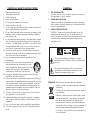
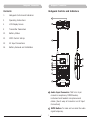
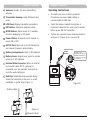
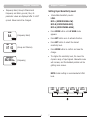
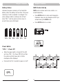
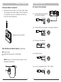
User Guide
ACT-30T Bodypack Transmitters
All rights reserved. Do not copy or forward without prior approvals MIPRO.
Specifications and design subject to change without notice.
MN 014/03
2 CE 3 4 7 F
WARNING
! IMPORTANT SAFETY INSTRUCTIONS !
1.
Read these instructions.
2.
Keep these instructions.
3.
Heed all warnings.
4.
Follow all instructions.
5.
Do not use this apparatus near water.
6.
Clean only with a dry cloth.
7.
Do not block any ventilation openings. Install in accordance
with the manufacturer's instructions.
8.
Do not install near any heat sources such as radiators, heat
registers, stoves, or other apparatus (including amplifiers)
that produce heat.
9.
Do not defeat the safety purpose of the polarised or ground
plug: A polarised plug has two blades with one wider than
the other. The wide blade is provided for your safety. When
the provided plug does not fit into your outlet, consult an
electrician for replacement of the obsolete outlet.
1.
FOR OUTDOOR USE:
To reduce the risk of fire or electric shock, do not expose
this apparatus to rain or moisture.
2.
UNDER WET LOCATION:
Apparatus should not be exposed to dripping or splashing
and no objects filled with liquids, such as vases should be
placed on the apparatus.
3.
SERVICE INSTRUCTIONS:
CAUTION - These servicing instructions are for use by
qualified service personnel only. To reduce the risk of
electric shock, do not perform any servicing other than that
contained in the operating instructions unless you are
qualified to do so.
10. Protect the power cord from being walked on or pinched
particularly at plug, convenience receptacles, and the point
where they exit from the apparatus.
11. Only use attachments/accessories specified by the
manufacturer.
This symbol indicates that dangerous voltage
constituting a risk of electric shock is present within
this unit.
12. Use only with a cart, stand, tripod, bracket, or
table specified by the manufacturer, or sold
with the apparatus. When a cart is used, use
caution when moving the cart/apparatus
combination to avoid injury from tip-over.
This symbol indicates that there are important
operating and maintenance instructions in the
literature accompanying this unit.
13. Unplug this apparatus during lightning storms or when
unused for long periods of time.
14. Refer all servicing to qualified service personnel. Servicing is
required when the apparatus has been damaged in any way,
such as power-supply cord or plug is damaged, liquid has
been spilled or objects have fallen into the apparatus, the
apparatus has been exposed to rain or moisture, does not
operate normally, or has been dropped.
Disposal Dispose of any unusable devices or batteries
responsibly and in accordance with any applicable
regulations.
Disposing of used batteries with domestic waste is
to be avoided!
15. To reduce the risk of fire or electric shock, do not expose
this apparatus to rain or moisture.
16. Apparatus should not be exposed to dripping or splashing
and no objects filled with liquids, should be placed on the
apparatus.
17. Use only with the battery which specified by manufacturer.
18. The power supply cord set is to be the main disconnected
device.
2005-08-13
Batteries / NiCad cells often contain heavy metals
such as cadmium(Cd), mercury(Hg) and lead(Pb)
that makes them unsuitable for disposal with
domestic waste. You may return spent batteries/
accumulators free of charge to recycling centres or
anywhere else batteries/accumulators are sold.
By doing so, you contribute to the conservation of
our environment!
Bodypack Transmitter
Bodypack Transmitter
Contents
1
Bodypack Controls and Indicators
3
Operating Instructions
4
LCD Display Screen
5
Transmitter Parameters
12
Battery Status
13
MUTE Control Set-Up
15
AF Input Connections
16
Battery Removal and Installation
Bodypack Controls and Indicators
1
2
3
4
5
6
7
8
GRP
CH
07 03
12
13
9
10
11
0
1
Audio Input Connector: TA4F mini 4-pin
connector accepts any MIPRO lavalier,
instrument and headset microphones and
cables. (See 5 ways of connection on AF Input
Connections)
2
MUTE Button: To mute and un-mute the audio
signal temporary.
1
Bodypack Transmitter
3
Antenna: Flexible 1/4 wave transmitting
antenna.
4
Transmitter Housing: Holds PCB board and
wires.
5
LCD Panel: Display transmitter parameters.
6
SET Button: Parameter selection button.
7
MODE Button: Allows access to 7 available
functions displaying in LCD panel.
Bodypack Transmitter
Operating Instructions
!
The audio gain level is factory preset at
Microphone-Low level. Guitar setting is
recommended at LINE level.
!
Insert the lavalier, headset microphone or
instrument cable into the audio input connector
before power ON the transmitter.
!
Tighten the connector screw clockwise direction
as shown in (Figure 2) for a secured fit.
8
Power Button: Press and hold 2 seconds to
power ON or OFF.
9
ACT IR Port: Align and syncs the transmitter
and receiver frequency automatically.
Capsule Connector
10
Battery Compartment: Holds 2 'AA' batteries.
Headset
Lavalier
11
Battery Cover: Hinged cover opens to provide
access to 2 'AA' batteries.
12
External Mute Connector: When an external
mute switch cable, MJ-70 (optional) is
connected, user can manually mute and unmute the audio temporary.
13
Belt Clip: Detachable and reversible design
allows the transmitter to be worn on a belt,
waistband, or guitar strap (Figure 1).
(Figure 2)
(Positive Wear)
(Figure 1)
(Opposite Wear)
The ridge on the
connector must align and
match the indentation on
the socket when inserting
for a proper fit.
2
3
Bodypack Transmitter
Bodypack Transmitter
LCD Display Screen
Transmitter Parameters
MODE button
!
GRP
07 03
A1
A2
Press “MODE” button to access one of the
7 parameters below.
CH
AF MUTE
A1
LCD Screen
A2
AF (audio) MUTE
A3
Transmitter Battery Meter
SET button
!
A3
Press “SET” button then the changeable
functions will twinkle. Change to the desired
parameters during the above twinkle by pressing
“SET” button.
GRP
CH
07 03
MODE
SET
B
C
D
FREQUENCY
AF GAIN
RF POWER
A
GRP
CH
07
03
MODE
4
MODE
802.000MHz
MODE
MIC-L
G
F
E
SET LOCK
MUTE MODE
BAND
UNLOCK
MODE
MANUAL
MODE
A
Group and Channel
B
Frequency
C
Sensitivity Level
D
RF Output Power
E
Frequency Band
F
MUTE Mode
G
Parameters Lock & Unlock Status
5
MODE
8A
RF-LOW
MODE
Bodypack Transmitter
!
Bodypack Transmitter
Frequency Band, Group & Channel and
Frequency are factory pre-set, thus, its
parameter values are displayed after it is ACT
synced. Values cannot be changed.
Setting Input Sensitivity Level
BAND
8A
GRP
!
4 Selectable Sensitivity Levels:
LINE、
MIC-L (MICROPHONE-LOW)、
MIC-M (MICROPHONE-MID)、
MIC-H (MICROPHONE-HIGH).
!
Press MODE button until AF GAIN mode
appears.
(Frequency Band)
!
Press SET button once to activate function.
!
Press SET button to select the desired
sensitivity level.
!
Press MODE button to confirm and save the
change.
!
The higher the sensitivity level, the lower the
dynamic range of input signals. Meanwhile noise
will increase, and the feedback problem will be
getting more serious.
CH
07 03
(Group and Channel)
FREQUENCY
802.000MHz
(Frequency)
NOTE: Guitar setting is recommended at LINE
level.
AF GAIN
AF GAIN
AF GAIN
AF GAIN
LINE
MIC-L
MIC-M
MIC-H
SET
SET
SET
6
7
SET
Bodypack Transmitter
Bodypack Transmitter
Setting RF Output Power
MUTE MODE
!
2 RF Output Power Levels: RF-LOW and RF-HI.
!
!
Press MODE button until RF POWER LOW or
RF POWER HIGH mode appears.
MUTE MODE: Select from MANUAL and
DISABLE.
!
Press MODE button until MUTE MODE appears.
Press SET button once, the LCD screen starts
flashing to denote it is ready to accept mode
changes. Press SET button to change between
MANUAL and DISABLE in cycle. Press MODE
button to confirm and save the change, or LCD
will stop flashing after 5 seconds and parameter
will be saved.
!
MUTE button is operable when MUTE MODE is
set in MANUAL mode.
!
MUTE button is not operable when MUTE
MODE is set in DISABLE mode.
!
Press SET button once to activate function.
!
Press SET button to select the desired RF output
power.
!
Press MODE button to confirm and save the
change.
RF POWER
RF POWER
RF-HI
RF-LOW
SET
MUTE MODE
MUTE MODE
MANUAL
DISABLE
SET
8
9
Bodypack Transmitter
Bodypack Transmitter
ERR Message
Setting LOCK
!
Setting LOCK can be switched to LOCK or
UNLOCK mode.
!
Press MODE button until SET LOCK mode
appears.
!
Press SET button to select the desired
parameter.
!
Press MODE button to confirm and save the
change.
!
Press SET button twice to remove the LOCK
function.
!
The LOCK function will be removed automatically
when losing power.
!
Mute function can still work properly when
LOCK.
!
NOTE: Once locked, all 7 parameter values
cannot be changed.
SET LOCK
SET LOCK
LOCK
UNLOCK
RF POWER
LOCKED
ERR no02
For testing only.
ERR no03
The frequency you want to program is
above the switching bandwidth of the
transmitter. Use a receiver with an
appropriate frequency group. (At this time
the microphone is still operating and the
frequency remains unchanged. To clear
the displayed "ERR" message, switch the
handheld transmitter off and on again.)
ERR no04
The frequency you want to program is
below the switching bandwidth of the
transmitter. Use a receiver with an
appropriate frequency group. (At this time
the microphone is still operating and the
frequency remains unchanged. To clear the
displayed “ERR” message, switch the
handheld transmitter off and on again.)
!
“Channel” Only: If “Channel” only is displayed,
it means that you are using a frequency which
is not pre-programmed.
SET
10
EEPROM is not being programmed or
internal data error.
“Group” & “Channel”: When both the group
and channel numbers are displayed, it means
that you are using the pre-programmed
frequency of the receiver.
MODE
RF POWER
ERR no01
!
SET
RF-HI
When “ERR” appears in the display it indicates
that an operational error has occurred. Please
refer to the following codes to diagnose which
error you are experiencing.
11
Bodypack Transmitter
Bodypack Transmitter
Battery Status
MUTE Control Set-Up
Indicates the power remaining in the transmitter
battery. When the battery has less than 10% power
remaining it must be replaced or recharged. If an
under voltage condition continues, the LCD will
show “OFF...” and the system will shut down to
prevent being overly discharged.
MUTE control enables audio to be muted or unmuted temporarily.
100%
80%
60%
40%
20%
!
Press MUTE button to mute audio temporarily.
Parameter values can be changed and ACT sync
activate during this MUTE mode.
!
Press MUTE button to un-mute.
10%
AF INPUT
MUTE
AF MUTE
Power Button
“OFF...” - Power Off
!
!
When the power switch is turned off, the LCD
will show “OFF...” (for Power Off) first and then
the system will shut down and no further
messages will be displayed.
CH
07
03
AF MUTE
Press and hold for 2 seconds to power on & off.
MODE
OFF...
12
B
C
D
FREQUENCY
AF GAIN
RF POWER
A
GRP
13
MODE
802.000MHz
AF MUTE
MODE
MIC-L
AF MUTE
MODE
G
F
E
SET LOCK
MUTE MODE
BAND
UNLOCK
AF MUTE
MODE
MANUAL
AF MUTE
MODE
8A
AF MUTE
RF-LOW
AF MUTE
MODE
Bodypack Transmitter
Bodypack Transmitter
AF Input Connections
External Mute Connector
!
External mute connector is a 3.5mm jack. When
an external mute switch cable, MJ-70 (optional)
is connected, user can manually mute and unmute the audio temporary.
(1) 2-Wire Electret condenser
microphone Capsule
SHIELD PIN
1
AUDIO
2
2
1
3
4
3
4
(2) 3-Wire Electret condenser microphone Capsule
SHIELD PIN
1
2
AUDIO
BIAS
External mute connector
2
1
3
4
3
4
(3) Dynamic Microphone
2 1
SHIELD PIN
1
3
2
AUDIO
3.5mm jack.
B2
External mute switch on/off button.
4
4
MJ-70 External Mute Switch (optional)
B1
2
1
3
3
(4) Electric Guitar
SHIELD PIN
1
2
AUDIO
NOTE: Plug in the device before power on the
bodypack transmitter.
2
1
3
4
3
4
B1
(5) Line-in (Impedance 8KΩ ATT. 10dB)
SHIELD PIN
1
AUDIO
2
B2
3
4
14
15
2
1
3
4
Bodypack Transmitter
Bodypack Transmitter
& IC - ID
Battery Removal and Installation
Pushing down both snap locks on the sides to open
battery compartment cover. Take out the two
batteries. (Figure 3)
Insert two fresh AA batteries (alkaline type is
recommended) into the battery compartment
according to the correct polarity (- and +) as shown
in (Figure 4). Then close the battery compartment
cover tightly.
THIS DEVICE COMPLIES WITH PART74 OF THE FCC RULES
AND RSS-123 ISSUE2 OF CANADA. OPERATION IS
SUBJECT TO THE FOLLOWING TWO CONDITIONS:
(1) This device may not cause interference.
(2) This device must accept any interference, including
interference that may cause undesired operation of the
device. This equipment complies with FCC RF radiation
exposure limits set forth for an uncontrolled environment.
Le présent appareil est conforme aux CNR d'Industrie
Canada applicables aux appareils radio
exempts de licence. L'exploitation est autorisée aux deux
conditions suivantes :
(1) l'appareil ne doit pas produire de brouillage, et
(2) l'utilisateur de l'appareil doit accepter tout brouillage
radioélectrique subi, même si le brouillage est susceptible
d'en compromettre le fonctionnement.
(Figure 3)
(Figure 4)
Caution:
Remove the batteries if unused for a long period of
time to prevent battery leakage, corrosion and
causes possible damage to electronics.
16
17