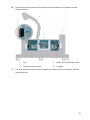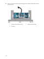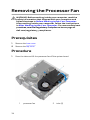
1
Alienware Alpha
Service Manual
Computer Model: Alienware Alpha
Regulatory Model: D07U
Regulatory Type: D07U001
Notes, Cautions, and Warnings
NOTE: A NOTE indicates important information that helps you make better use
of your computer.
CAUTION: A CAUTION indicates either potential damage to
hardware or loss of data and tells you how to avoid the problem.
WARNING: A WARNING indicates a potential for property damage,
personal injury, or death.
Copyright © 2014 Dell Inc. All rights reserved. This product is protected by U.S. and
international copyright and intellectual property laws. Dell™ and the Dell logo are trademarks of
Dell Inc. in the United States and/or other jurisdictions. All other marks and names mentioned
herein may be trademarks of their respective companies.
2014 - 10
Rev. A00
Contents
Before Working Inside Your Computer........................ 8
Before You Begin ................................................................................................ 8
Safety Instructions..............................................................................................8
Recommended Tools.........................................................................................10
After Working Inside Your Computer...........................11
Technical Overview..............................................................12
Inside View Of Your Computer........................................................................... 12
System-Board Components.............................................................................. 13
Removing the Base Cover.................................................14
Procedure...........................................................................................................14
Replacing the Base Cover................................................. 16
Procedure...........................................................................................................16
Removing the Top Cover................................................... 17
Prerequisites...................................................................................................... 17
Procedure........................................................................................................... 17
Replacing the Top Cover................................................... 19
Procedure...........................................................................................................19
Post-requisites.................................................................................................. 19
Removing the Hard Drive.................................................20
Prerequisites.....................................................................................................20
Procedure..........................................................................................................20
Replacing the Hard Drive................................................. 23
Procedure.......................................................................................................... 23
Post-requisites..................................................................................................23
Removing the Bottom USB Port................................... 24
Prerequisites.....................................................................................................24
Procedure.......................................................................................................... 24
Replacing the Bottom USB Port....................................28
Procedure..........................................................................................................28
Post-requisites..................................................................................................28
Removing the Power-Button Board............................29
Prerequisites.....................................................................................................29
Procedure.......................................................................................................... 29
Replacing the Power-Button Board............................ 33
Procedure..........................................................................................................33
Post-requisites..................................................................................................33
Removing the Processor Fan......................................... 34
Prerequisites.....................................................................................................34
Procedure..........................................................................................................34
Replacing the Processor Fan......................................... 36
Procedure..........................................................................................................36
Post-requisites..................................................................................................36
Removing the Processor Heat-Sink............................37
Prerequisites..................................................................................................... 37
Procedure.......................................................................................................... 37
Replacing the Processor Heat-Sink............................ 39
Procedure..........................................................................................................39
Post-requisites..................................................................................................39
Removing the Video-Card Fan.......................................40
Prerequisites.....................................................................................................40
Procedure..........................................................................................................40
Replacing the Video-Card Fan........................................42
Procedure.......................................................................................................... 42
Post-requisites..................................................................................................42
Removing the Video-Card Heat Sink.......................... 43
Prerequisites.....................................................................................................43
Procedure..........................................................................................................44
Replacing the Video-Card Heat Sink...........................45
Procedure..........................................................................................................45
Post-requisites..................................................................................................45
Removing the Memory Module(s)............................... 46
Prerequisites.....................................................................................................46
Procedure..........................................................................................................46
Replacing the Memory Module(s)................................48
Procedure..........................................................................................................48
Post-requisites..................................................................................................49
Removing the Processor..................................................50
Prerequisites.....................................................................................................50
Procedure..........................................................................................................50
Replacing the Processor.................................................. 52
Procedure.......................................................................................................... 52
Post-requisites..................................................................................................53
Removing the Front-Panel Light Board.................... 54
Prerequisites.....................................................................................................54
Procedure..........................................................................................................54
Replacing the Front-Panel Light Board..................... 57
Procedure.......................................................................................................... 57
Post-requisites.................................................................................................. 57
Removing the Wireless Card.......................................... 58
Prerequisites.....................................................................................................58
Procedure..........................................................................................................58
Replacing the Wireless Card...........................................60
Procedure..........................................................................................................60
Post-requisites................................................................................................. 60
Removing the Antenna Modules.................................. 61
Prerequisites......................................................................................................61
Procedure.......................................................................................................... 62
Replacing the Antenna Modules.................................. 64
Procedure..........................................................................................................64
Post-requisites..................................................................................................64
Removing the System Board......................................... 65
Prerequisites.....................................................................................................65
Procedure..........................................................................................................66
Replacing the System Board..........................................69
Procedure..........................................................................................................69
Post-requisites..................................................................................................69
Removing the Coin-Cell Battery..................................... 71
Prerequisites...................................................................................................... 71
Procedure........................................................................................................... 71
Replacing the Coin-Cell Battery.................................... 73
Procedure.......................................................................................................... 73
Post-requisites.................................................................................................. 73
System Setup.........................................................................74
Overview ........................................................................................................... 74
Entering System Setup .................................................................................... 74
System Setup Options...................................................................................... 74
Boot Sequence..................................................................................................80
Changing Boot Sequence for the Current Boot..........................................80
Changing Boot Sequence for Future Boots.................................................81
Clearing Forgotten Passwords.......................................................................... 81
Prerequisites...............................................................................................82
Procedure.................................................................................................... 82
Post-requisites............................................................................................84
Clearing CMOS Settings....................................................................................84
Prerequisites...............................................................................................84
Procedure....................................................................................................84
Post-requisites............................................................................................86
Flashing the BIOS................................................................. 87
Before Working Inside Your
Computer
CAUTION: To avoid damaging the components and cards,
handle them by their edges and avoid touching pins and
contacts.
NOTE: The images in this document may differ from your computer
depending on the configuration you ordered.
Before You Begin
1
Save and close all open files and exit all open applications.
2
Shut down your computer.
–
Windows 8.1: On the Start screen, click or tap the power icon
Shut down.
–
Console Mode: On the Home screen, click Power → SHUT DOWN.
→
NOTE: If you are using a different operating system, see the
documentation of your operating system for shut-down instructions.
3
Disconnect your computer and all attached devices from their electrical
outlets.
4
Disconnect all cables such as telephone cables, network cables and so on,
from your computer.
5
Disconnect all attached devices and peripherals, such as keyboard, mouse,
monitor, and so on, from your computer.
6
Remove any media card and optical disc from your computer, if applicable.
7
After the computer is unplugged, press and hold the power button for 5
seconds to ground the system board.
Safety Instructions
Use the following safety guidelines to protect your computer from potential
damage and ensure your personal safety.
8
WARNING: Before working inside your computer, read the
safety information that shipped with your computer. For
more safety best practices, see the Regulatory Compliance
home page at dell.com/regulatory_compliance.
WARNING: Disconnect all power sources before opening the
computer cover or panels. After you finish working inside
the computer, replace all covers, panels, and screws before
connecting to the power source.
CAUTION: To avoid damaging the computer, make sure that
the work surface is flat and clean.
CAUTION: To avoid damaging the components and cards,
handle them by their edges and avoid touching pins and
contacts.
CAUTION: You should only perform troubleshooting and
repairs as authorized or directed by the Dell technical
assistance team. Damage due to servicing that is not
authorized by Dell is not covered by your warranty. See the
safety instructions that shipped with the product or at
dell.com/regulatory_compliance.
CAUTION: Before touching anything inside your computer,
ground yourself by touching an unpainted metal surface,
such as the metal at the back of the computer. While you
work, periodically touch an unpainted metal surface to
dissipate static electricity, which could harm internal
components.
CAUTION: When you disconnect a cable, pull on its connector
or on its pull-tab, not on the cable itself. Some cables have
connectors with locking tabs or thumb-screws that you
must disengage before disconnecting the cable. When
disconnecting cables, keep them evenly aligned to avoid
bending any connector pins. When connecting cables, make
sure that the ports and connectors are correctly oriented
and aligned.
CAUTION: To disconnect a network cable, first unplug the
cable from your computer and then unplug the cable from
the network device.
9
CAUTION: Press and eject any installed card from the mediacard reader.
Recommended Tools
The procedures in this document may require the following tools:
•
Philips screwdriver
•
Flat-head screwdriver
•
Plastic scribe
10
After Working Inside Your
Computer
CAUTION: Leaving stray or loose screws inside your
computer may severely damage your computer.
1
Replace all screws and make sure that no stray screws remain inside your
computer.
2
Connect any external devices, peripherals, and cables you removed before
working on your computer.
3
Replace any media cards, discs, and any other part(s) that you removed
before working on your computer.
4
Connect your computer and all attached devices to their electrical outlets.
5
Turn on your computer.
11
Technical Overview
WARNING: Before working inside your computer, read the
safety information that shipped with your computer and
follow the steps in Before Working Inside Your Computer.
After working inside your computer, follow the instructions
in After Working Inside Your Computer. For more safety best
practices, see the Regulatory Compliance home page at
dell.com/regulatory_compliance.
Inside View Of Your Computer
1
video-card fan
2
back panel
3
processor fan
4
power-button module
5
front-panel light module
12
System-Board Components
1
processor socket
2
processor-fan cable connector
(CPU_FAN)
3
clear password jumper
(CLEAR_PASSWORD)
4
power-button connector
(ALIEN_HEAD)
5
memory-module slot (DIMM2)
6
memory-module slot (DIMM1)
7
video-card fan cable connector
(GPU_FAN)
8
front-panel light board cable
connector (LOGO)
9
USB-port cable connector
(INT_USB2)
10
wireless-card slot
11
clear CMOS jumper (RTCRST)
12
video card
13
Removing the Base Cover
WARNING: Before working inside your computer, read the
safety information that shipped with your computer and
follow the steps in Before Working Inside Your Computer.
After working inside your computer, follow the instructions
in After Working Inside Your Computer. For more safety best
practices, see the Regulatory Compliance home page at
dell.com/regulatory_compliance.
Procedure
1
Turn the computer over.
2
Remove the screws that secure the base cover to the top cover.
1
14
screws (4)
2
base cover
3
Using a plastic scribe, pry the base cover off the top cover.
1
plastic scribe
2
base cover
15
Replacing the Base Cover
WARNING: Before working inside your computer, read the
safety information that shipped with your computer and
follow the steps in Before Working Inside Your Computer.
After working inside your computer, follow the instructions
in After Working Inside Your Computer. For more safety best
practices, see the Regulatory Compliance home page at
dell.com/regulatory_compliance.
Procedure
1
Align the screw holes on the base cover with the screw holes on the top
cover and snap the base cover over the top cover.
2
Replace the screws that secure the base cover to the top cover.
16
Removing the Top Cover
WARNING: Before working inside your computer, read the
safety information that shipped with your computer and
follow the steps in Before Working Inside Your Computer.
After working inside your computer, follow the instructions
in After Working Inside Your Computer. For more safety best
practices, see the Regulatory Compliance home page at
dell.com/regulatory_compliance.
Prerequisites
Remove the base cover.
Procedure
1
Hold the chassis along with the top cover and then turn the computer
over.
17
2
Lift the top cover off the chassis.
1
18
top cover
Replacing the Top Cover
WARNING: Before working inside your computer, read the
safety information that shipped with your computer and
follow the steps in Before Working Inside Your Computer.
After working inside your computer, follow the instructions
in After Working Inside Your Computer. For more safety best
practices, see the Regulatory Compliance home page at
dell.com/regulatory_compliance.
Procedure
1
Align the slots on the top cover with the ports on the chassis and place the
top cover on the chassis.
2
Hold the chassis along with the top cover and then turn the computer
over.
Post-requisites
Replace the base cover.
19
Removing the Hard Drive
WARNING: Before working inside your computer, read the
safety information that shipped with your computer and
follow the steps in Before Working Inside Your Computer.
After working inside your computer, follow the instructions
in After Working Inside Your Computer. For more safety best
practices, see the Regulatory Compliance home page at
dell.com/regulatory_compliance.
CAUTION: Hard drives are fragile. Exercise care when
handling the hard drive.
CAUTION: To avoid data loss, do not remove the hard drive
while the computer is in sleep or on state.
Prerequisites
Remove the base cover.
Procedure
1
Remove the screw that secures the hard-drive assembly to the chassis.
2
Slide the hard-drive assembly towards the back of the computer to
disconnect the hard drive from the system board.
20
3
Lift the hard-drive assembly off the chassis.
1
4
screw
2
hard-drive assembly
Remove the screws that secure the hard-drive bracket to the hard drive.
21
5
22
Lift the hard drive off the hard-drive bracket.
1
hard-drive bracket
3
screws (4)
2
hard drive
Replacing the Hard Drive
WARNING: Before working inside your computer, read the
safety information that shipped with your computer and
follow the steps in Before Working Inside Your Computer.
After working inside your computer, follow the instructions
in After Working Inside Your Computer. For more safety best
practices, see the Regulatory Compliance home page at
dell.com/regulatory_compliance.
CAUTION: Hard drives are fragile. Exercise care when
handling the hard drive.
Procedure
1
Align the screw holes on the hard drive with the screw holes on the harddrive bracket.
2
Replace the screws that secure the hard-drive bracket to the hard drive.
3
Align the slots on the hard-drive assembly with the tabs on the chassis.
4
Slide the hard-drive assembly towards the front of the computer to
connect the hard drive to the system board.
5
Replace the screw that secures the hard-drive assembly to the chassis.
Post-requisites
1
Replace the top cover.
2
Replace the base cover.
23
Removing the Bottom USB
Port
WARNING: Before working inside your computer, read the
safety information that shipped with your computer and
follow the steps in Before Working Inside Your Computer.
After working inside your computer, follow the instructions
in After Working Inside Your Computer. For more safety best
practices, see the Regulatory Compliance home page at
dell.com/regulatory_compliance.
Prerequisites
1
Remove the base cover.
2
Remove the top cover.
Procedure
1
24
Disconnect the USB-port cable from the system board.
2
Push down the USB-port cable through the cable-routing hole on the
chassis.
1
USB-port cable
2
routing hole
3
Turn the computer over.
4
Remove the USB-port cable from the routing guides on the chassis.
5
Remove the screw that secures the USB-port bracket to the chassis.
6
Lift the USB-port bracket at an angle to release the tabs on the USB-port
bracket from the slots on the chassis.
25
7
8
26
Lift the USB-port bracket off the chassis.
1
screw
2
USB-port bracket
3
chassis
4
USB-port cable
5
routing guides
Remove the screw that secures the USB port to the chassis.
9
Slide and remove the USB port, along with the cable, from under the tab on
the chassis.
1
screw
2
tab
3
USB port
4
chassis
5
USB-port cable
27
Replacing the Bottom USB
Port
WARNING: Before working inside your computer, read the
safety information that shipped with your computer and
follow the steps in Before Working Inside Your Computer.
After working inside your computer, follow the instructions
in After Working Inside Your Computer. For more safety best
practices, see the Regulatory Compliance home page at
dell.com/regulatory_compliance.
Procedure
1
Slide the USB port under the tab on the chassis.
2
Replace the screw that secures the USB port to the chassis.
3
Align and slide the tabs on USB-port bracket in the slots on the chassis.
4
Replace the screw that secures the USB-port bracket to the chassis
5
Route the USB-port cable through the routing guides on the chassis and
slide the cable through the cable-routing hole on the chassis.
6
Turn the computer over.
7
Connect the USB-port cable to the system board.
Post-requisites
1
Replace the top cover.
2
Replace the base cover.
28
Removing the Power-Button
Board
WARNING: Before working inside your computer, read the
safety information that shipped with your computer and
follow the steps in Before Working Inside Your Computer.
After working inside your computer, follow the instructions
in After Working Inside Your Computer. For more safety best
practices, see the Regulatory Compliance home page at
dell.com/regulatory_compliance.
Prerequisites
1
Remove the base cover.
2
Remove the top cover.
Procedure
1
Disconnect the power-button board cable from the system board.
2
Turn the chassis over and remove the antenna cable from the routing
guides on the power-button module.
3
Press the tabs on the power-button module to release the module from
the front panel.
4
Release the tabs at the bottom of the power-button module from the slots
on the chassis.
29
5
30
Remove the power-button module along with its cable through the slot on
the front panel.
1
tabs (2)
2
routing guides
3
tabs (2)
4
power-button module
5
power-button board cable
6
7
Push the tab that secures the power-button board to the power-button
board bracket.
1
tab
2
power-button board cable
3
power-button board
4
bracket
Lift and slide the power-button board to release it from the power-button
board bracket.
31
8
32
Remove the power-button board along with its cable off the power-button
board bracket.
1
power-button board cable
3
bracket
2
power-button board
Replacing the Power-Button
Board
WARNING: Before working inside your computer, read the
safety information that shipped with your computer and
follow the steps in Before Working Inside Your Computer.
After working inside your computer, follow the instructions
in After Working Inside Your Computer. For more safety best
practices, see the Regulatory Compliance home page at
dell.com/regulatory_compliance.
Procedure
1
Use the alignment posts on power-button board bracket to align the
power-button board into the slot on the power-button board bracket.
2
Snap the power-button board in place on the power-button board bracket.
3
Route the power-button board cable through the cable-routing hole on the
chassis.
4
Align and snap the power-button module into the slot on the front panel.
5
Connect the power-button board cable to the system board.
6
Turn over the chassis and route the antenna cable through the routing
guides on the power-button board module.
Post-requisites
1
Replace the top cover.
2
Replace the base cover.
33
Removing the Processor Fan
WARNING: Before working inside your computer, read the
safety information that shipped with your computer and
follow the steps in Before Working Inside Your Computer.
After working inside your computer, follow the instructions
in After Working Inside Your Computer. For more safety best
practices, see the Regulatory Compliance home page at
dell.com/regulatory_compliance.
Prerequisites
1
Remove the base cover.
2
Remove the top cover.
Procedure
1
Press the tabs and lift the processor fan off the system board.
1
34
processor fan
2
tabs (2)
2
Disconnect the processor-fan cable from the system board.
1
processor fan
2
processor-fan cable
35
Replacing the Processor Fan
WARNING: Before working inside your computer, read the
safety information that shipped with your computer and
follow the steps in Before Working Inside Your Computer.
After working inside your computer, follow the instructions
in After Working Inside Your Computer. For more safety best
practices, see the Regulatory Compliance home page at
dell.com/regulatory_compliance.
Procedure
1
Connect the processor-fan cable to the system board.
2
Align and snap the processor fan over the processor heat sink.
Post-requisites
1
Replace the top cover.
2
Replace the base cover.
36
Removing the Processor
Heat-Sink
WARNING: Before working inside your computer, read the
safety information that shipped with your computer and
follow the steps in Before Working Inside Your Computer.
After working inside your computer, follow the instructions
in After Working Inside Your Computer. For more safety best
practices, see the Regulatory Compliance home page at
dell.com/regulatory_compliance.
CAUTION: For maximum cooling of the processor, do not
touch the heat transfer areas on the heat sink. The oils in
your skin can reduce the heat transfer capability of the
thermal grease.
Prerequisites
1
Remove the base cover.
2
Remove the top cover.
3
Remove the processor fan.
Procedure
NOTE: The original thermal grease can be reused if the original processor
and heat sink are reinstalled together. If either the processor or the heat
sink is replaced, use the thermal grease provided in the kit to make sure
that thermal conductivity is achieved.
1
Loosen the captive screws that secure the processor heat sink to the
system board.
37
2
Lift the processor heat sink off system board.
1
38
processor heat sink
2
captive screws (4)
Replacing the Processor
Heat-Sink
WARNING: Before working inside your computer, read the
safety information that shipped with your computer and
follow the steps in Before Working Inside Your Computer.
After working inside your computer, follow the instructions
in After Working Inside Your Computer. For more safety best
practices, see the Regulatory Compliance home page at
dell.com/regulatory_compliance.
CAUTION: For maximum cooling of the processor, do not
touch the heat transfer areas on the heat sink. The oils in
your skin can reduce the heat transfer capability of the
thermal grease.
Procedure
CAUTION: Incorrect alignment of the heat sink may damage
the system board and processor.
NOTE: The original thermal grease can be reused if the original processor
and heat sink are reinstalled together. If either the processor or the heat
sink is replaced, use the thermal grease provided in the kit to make sure
that thermal conductivity is achieved.
1
Place the processor heat sink over the processor.
2
Align the captive screws on the processor heat sink with the screw holes
on the system board.
3
Tighten the captive screws that secure the processor heat sink to the
system board.
Post-requisites
1
Replace the processor fan.
2
Replace the top cover.
3
Replace the base cover.
39
Removing the Video-Card
Fan
WARNING: Before working inside your computer, read the
safety information that shipped with your computer and
follow the steps in Before Working Inside Your Computer.
After working inside your computer, follow the instructions
in After Working Inside Your Computer. For more safety best
practices, see the Regulatory Compliance home page at
dell.com/regulatory_compliance.
Prerequisites
1
Remove the base cover.
2
Remove the top cover.
Procedure
1
40
Disconnect the video-card fan cable from the system board.
2
Press the tabs and lift the video-card fan off the system board.
1
video-card fan
3
video-card fan cable
2
tabs (2)
41
Replacing the Video-Card
Fan
WARNING: Before working inside your computer, read the
safety information that shipped with your computer and
follow the steps in Before Working Inside Your Computer.
After working inside your computer, follow the instructions
in After Working Inside Your Computer. For more safety best
practices, see the Regulatory Compliance home page at
dell.com/regulatory_compliance.
Procedure
1
Align and snap the video-card fan over the video-card heat sink.
2
Connect the video-card fan cable to the system board.
Post-requisites
1
Replace the top cover.
2
Replace the base cover.
42
Removing the Video-Card
Heat Sink
WARNING: Before working inside your computer, read the
safety information that shipped with your computer and
follow the steps in Before Working Inside Your Computer.
After working inside your computer, follow the instructions
in After Working Inside Your Computer. For more safety best
practices, see the Regulatory Compliance home page at
dell.com/regulatory_compliance.
CAUTION: For maximum cooling of the processor, do not
touch the heat transfer areas on the heat sink. The oils in
your skin can reduce the heat transfer capability of the
thermal grease.
Prerequisites
1
Remove the base cover.
2
Remove the top cover.
3
Remove the video-card fan.
43
Procedure
NOTE: The original thermal grease can be reused if the original video card
and heat sink are reinstalled together. If either the video card or the heat
sink is replaced, use the thermal grease provided in the kit to make sure
that thermal conductivity is achieved.
1
In sequential order (indicated on the heat sink), loosen the captive screws
that secure the video-card heat sink to the system board.
1
2
44
video-card heat sink
2
captive screws (4)
Lift the video-card heat sink off the video-card heat sink.
Replacing the Video-Card
Heat Sink
WARNING: Before working inside your computer, read the
safety information that shipped with your computer and
follow the steps in Before Working Inside Your Computer.
After working inside your computer, follow the instructions
in After Working Inside Your Computer. For more safety best
practices, see the Regulatory Compliance home page at
dell.com/regulatory_compliance.
CAUTION: For maximum cooling of the processor, do not
touch the heat transfer areas on the heat sink. The oils in
your skin can reduce the heat transfer capability of the
thermal grease.
Procedure
CAUTION: Incorrect alignment of the heat sink may damage
the system board and video card.
NOTE: The original thermal grease can be reused if the original video card
and heat sink are reinstalled together. If either the video card or the heat
sink is replaced, use the thermal grease provided in the kit to make sure
that thermal conductivity is achieved.
1
Place the heat sink over the video card.
2
Align the captive screws on the video-card heat sink with the screw holes
on the system board.
3
In sequential order (indicated on the heat sink), tighten the captive screws
that secure the video-card heat sink to the system board.
Post-requisites
1
Replace the video-card fan.
2
Replace the top cover.
3
Replace the base cover.
45
Removing the Memory
Module(s)
WARNING: Before working inside your computer, read the
safety information that shipped with your computer and
follow the steps in Before Working Inside Your Computer.
After working inside your computer, follow the instructions
in After Working Inside Your Computer. For more safety best
practices, see the Regulatory Compliance home page at
dell.com/regulatory_compliance.
Prerequisites
1
Remove the base cover.
2
Remove the top cover.
3
Remove the processor fan.
Procedure
1
46
Using your fingertips, pry apart the securing clips on each end of the
memory-module slot until the memory module pops up.
2
Slide and remove the memory module from the memory-module slot.
1
memory-module slot
3
securing clips (2)
2
memory module
47
Replacing the Memory
Module(s)
WARNING: Before working inside your computer, read the
safety information that shipped with your computer and
follow the steps in Before Working Inside Your Computer.
After working inside your computer, follow the instructions
in After Working Inside Your Computer. For more safety best
practices, see the Regulatory Compliance home page at
dell.com/regulatory_compliance.
Procedure
1
48
Align the notch on the memory module with the tab on the memorymodule slot.
2
Slide the memory module into the memory-module slot and press the
memory module down until it clicks into place.
NOTE: If you do not hear the click, remove the memory module and
reinstall it.
1
memory module
2
notch
3
tab
4
memory-module slot
Post-requisites
1
Replace the processor fan.
2
Replace the top cover.
3
Replace the base cover.
49
Removing the Processor
WARNING: Before working inside your computer, read the
safety information that shipped with your computer and
follow the steps in Before Working Inside Your Computer.
After working inside your computer, follow the instructions
in After Working Inside Your Computer. For more safety best
practices, see the Regulatory Compliance home page at
dell.com/regulatory_compliance.
Prerequisites
1
Remove the base cover.
2
Remove the top cover.
3
Remove the processor fan.
4
Remove the processor heat sink.
Procedure
1
Press the release lever down and then push it away from the processor to
release it from the tab.
2
Extend the release lever completely and open the processor cover.
50
3
Lift the processor off the processor socket.
1
release lever
2
tab
3
processor cover
4
processor socket
5
processor
51
Replacing the Processor
WARNING: Before working inside your computer, read the
safety information that shipped with your computer and
follow the steps in Before Working Inside Your Computer.
After working inside your computer, follow the instructions
in After Working Inside Your Computer. For more safety best
practices, see the Regulatory Compliance home page at
dell.com/regulatory_compliance.
CAUTION: If either the processor or the heat sink is replaced,
use the thermal grease provided in the kit to make sure that
thermal conductivity is achieved.
Procedure
1
Make sure that the release lever on the processor socket is fully extended
and the processor cover is fully open.
CAUTION: Position the processor correctly in the
processor socket to avoid permanent damage to the
processor.
2
Align the notches on the processor with the tabs on the processor socket.
3
Align the pin-1 corner on the processor with the pin-1 corner on the
processor socket, and then place the processor in the processor socket.
CAUTION: Make sure that the processor-cover notch is
positioned underneath the alignment post.
4
52
When the processor is fully seated in the socket, close the processor cover.
5
Pivot the release lever down and place it under the tab on the processor
cover.
1
processor socket
2
processor
3
tab
4
processor cover
5
release lever
Post-requisites
1
Replace the processor heat sink.
2
Replace the processor fan.
3
Replace the top cover.
4
Replace the base cover.
53
Removing the Front-Panel
Light Board
WARNING: Before working inside your computer, read the
safety information that shipped with your computer and
follow the steps in Before Working Inside Your Computer.
After working inside your computer, follow the instructions
in After Working Inside Your Computer. For more safety best
practices, see the Regulatory Compliance home page at
dell.com/regulatory_compliance.
Prerequisites
1
Remove the base cover.
2
Remove the top cover.
3
Remove the video-card fan.
Procedure
1
54
Disconnect the front-panel light board cable from the system board.
2
Slide the front-panel light board cable through the routing-hole on the
chassis.
1
front-panel light board cable
2
routing hole
55
3
4
56
Press the front-panel light module tabs to release the module from the
front panel.
1
front-panel light module
3
front panel
2
tabs
Lift the front-panel light module, along with its cable, off the front panel.
Replacing the Front-Panel
Light Board
WARNING: Before working inside your computer, read the
safety information that shipped with your computer and
follow the steps in Before Working Inside Your Computer.
After working inside your computer, follow the instructions
in After Working Inside Your Computer. For more safety best
practices, see the Regulatory Compliance home page at
dell.com/regulatory_compliance.
Procedure
1
Align the tabs on the front-panel light module with the slots on the front
panel, and snap the front-panel light module onto the front panel.
2
Route the front-panel light board cable through the cable-routing hole on
the chassis.
3
Connect the front-panel light board cable to the system board.
Post-requisites
1
Replace the video-card fan.
2
Replace the top cover.
3
Replace the base cover.
57
Removing the Wireless Card
WARNING: Before working inside your computer, read the
safety information that shipped with your computer and
follow the steps in Before Working Inside Your Computer.
After working inside your computer, follow the instructions
in After Working Inside Your Computer. For more safety best
practices, see the Regulatory Compliance home page at
dell.com/regulatory_compliance.
Prerequisites
1
Remove the base cover.
2
Remove the top cover.
3
Remove the video-card fan.
Procedure
1
Remove the screw that secures the wireless card to the system board.
2
Lift the protective cover off the wireless card.
3
Disconnect the antenna cables from the wireless card.
58
4
Slide and remove the wireless card out of the wireless-card slot.
1
protective cover
2
screw
3
antenna cables (2)
4
wireless card
59
Replacing the Wireless Card
WARNING: Before working inside your computer, read the
safety information that shipped with your computer and
follow the steps in Before Working Inside Your Computer.
After working inside your computer, follow the instructions
in After Working Inside Your Computer. For more safety best
practices, see the Regulatory Compliance home page at
dell.com/regulatory_compliance.
Procedure
CAUTION: To avoid damage to the wireless card, do not place
any cables under it.
1
Align the notch on the wireless card with the tab on the wireless-card slot.
2
Connect the antenna cables to the wireless card.
A label at the tip of the antenna cables indicates color scheme for the
wireless card supported by your computer.
Connectors on the wireless card
Antenna-cable sticker
color
Auxiliary (1)
White
Main (2)
Black
3
Slide the wireless card at an angle into the wireless-card slot.
4
Press the other end of the wireless card down and replace the protective
cover on the wireless card.
5
Replace the screw that secures the wireless card to the system board.
Post-requisites
1
Replace the video-card fan.
2
Replace the top cover.
3
Replace the base cover.
60
Removing the Antenna
Modules
WARNING: Before working inside your computer, read the
safety information that shipped with your computer and
follow the steps in Before Working Inside Your Computer.
After working inside your computer, follow the instructions
in After Working Inside Your Computer. For more safety best
practices, see the Regulatory Compliance home page at
dell.com/regulatory_compliance.
Prerequisites
1
Remove the base cover.
2
Remove the top cover.
3
Remove the video-card fan.
4
Remove the wireless card.
61
Procedure
1
Slide the antenna cables through the cable-routing hole on the chassis.
1
antenna cables (2)
2
routing hole
2
Turn the computer over.
3
Remove the antenna cable from the routing guides on the power-button
module and chassis.
4
Remove the screws that secure the antenna modules to the chassis.
62
5
6
Using a plastic scribe, pry and slide the antenna modules, and release the
tabs on the antenna modules from the slots on the chassis.
1
routing guides
2
screws (2)
3
antenna modules (2)
4
antenna cable
Lift the antenna modules, along with the cable, off the chassis.
63
Replacing the Antenna
Modules
WARNING: Before working inside your computer, read the
safety information that shipped with your computer and
follow the steps in Before Working Inside Your Computer.
After working inside your computer, follow the instructions
in After Working Inside Your Computer. For more safety best
practices, see the Regulatory Compliance home page at
dell.com/regulatory_compliance.
Procedure
1
Align and slide the tabs on the antenna modules in the slots on the
chassis.
2
Align the screw holes on the antenna modules with the screws hole on the
chassis.
3
Replace the screws that secure the antenna modules to the chassis.
4
Route the antenna cable through the routing guides on the chassis and
power-button module.
5
Route the antenna cable through the cable-routing hole on the chassis.
Post-requisites
1
Replace the wireless card.
2
Replace the video-card fan.
3
Replace the top cover.
4
Replace the base cover.
64
Removing the System Board
WARNING: Before working inside your computer, read the
safety information that shipped with your computer and
follow the steps in Before Working Inside Your Computer.
After working inside your computer, follow the instructions
in After Working Inside Your Computer. For more safety best
practices, see the Regulatory Compliance home page at
dell.com/regulatory_compliance.
NOTE: Your computer’s Service Tag is stored in the system board. You
must enter the Service Tag in the BIOS setup program after you replace
the system board.
NOTE: Replacing the system board removes any changes you have made
to the BIOS using the BIOS setup program. You must make the desired
changes again after you replace the system board.
NOTE: Before disconnecting the cables from the system board, note the
location of the connectors so that you can reconnect them correctly after
you replace the system board.
Prerequisites
1
Remove the base cover.
2
Remove the top cover.
3
Remove the hard drive.
4
Remove the processor fan.
5
Remove the processor heat sink.
6
Remove the processor.
7
Remove the video-card fan.
8
Remove the video-card heat sink.
9
Remove the memory modules.
10 Remove the wireless card.
65
Procedure
1
Disconnect the USB-port cable, front-panel light board cable, and powerbutton board cable from the system board.
For information on the location of connectors, see “System- Board
Components”.
2
66
1
power-button board cable
3
USB-port cable
2
front-panel light board
cable
Remove the screws that secure the back panel to the chassis.
3
4
Push the tab at the bottom of the back panel and remove the back panel
from the chassis.
1
screws (2)
3
tab
2
back panel
Remove the screws that secure the system board to the chassis.
67
5
Lift the system board at an angle and remove it from the chassis.
1
68
system board
2
screws (4)
Replacing the System Board
WARNING: Before working inside your computer, read the
safety information that shipped with your computer and
follow the steps in Before Working Inside Your Computer.
After working inside your computer, follow the instructions
in After Working Inside Your Computer. For more safety best
practices, see the Regulatory Compliance home page at
dell.com/regulatory_compliance.
NOTE: Your computer’s Service Tag is stored in the system board. You
must enter the Service Tag in the BIOS setup program after you replace
the system board.
NOTE: Replacing the system board removes any changes you have made
to the BIOS using the BIOS setup program. You must make the desired
changes again after you replace the system board.
Procedure
NOTE: Make sure that no cables are under the system board.
1
Slide the system board into the slot on the chassis and align the screw
holes on the system board with the screw holes on the chassis.
2
Replace the screws that secure the system board to the chassis.
3
Align and snap the back panel onto the chassis.
4
Align the screw holes on the back panel with the screw holes on the
chassis and replace the screws that secure the back panel to the chassis.
5
Connect the USB-port cable, front-panel light board cable, and powerbutton board cable to the system board.
For more information on the location of connectors, see “System-Board
Components”.
Post-requisites
1
Replace the wireless card.
2
Replace the memory modules.
3
Replace the video-card heat sink.
4
Replace the video-card fan.
69
5
Replace the processor.
6
Replace the processor heat sink.
7
Replace the processor fan.
8
Replace the hard drive.
9
Replace the top cover.
10 Replace the base cover.
70
Removing the Coin-Cell
Battery
WARNING: Before working inside your computer, read the
safety information that shipped with your computer and
follow the steps in Before Working Inside Your Computer.
After working inside your computer, follow the instructions
in After Working Inside Your Computer. For more safety best
practices, see the Regulatory Compliance home page at
dell.com/regulatory_compliance.
CAUTION: Removing the coin-cell battery resets the BIOS
settings to default. It is recommended that you note the
BIOS settings before removing the coin-cell battery.
Prerequisites
1
Remove the base cover.
2
Remove the top cover.
3
Remove the hard drive.
4
Remove the processor fan.
5
Remove the processor heat sink.
6
Remove the processor.
7
Remove the video-card fan.
8
Remove the video-card heat sink.
9
Remove the memory modules.
10 Remove the wireless card.
11
Remove the system board.
Procedure
1
Turn the system board over.
2
Disconnect the coin-cell battery cable from the system board.
71
3
72
Peel off the coin-cell battery from the system board.
1
coin-cell battery
3
system board
2
coin-cell battery cable
Replacing the Coin-Cell
Battery
WARNING: Before working inside your computer, read the
safety information that shipped with your computer and
follow the steps in Before Working Inside Your Computer.
After working inside your computer, follow the instructions
in After Working Inside Your Computer. For more safety best
practices, see the Regulatory Compliance home page at
dell.com/regulatory_compliance.
Procedure
1
Adhere the coin-cell battery to the system board.
2
Connect the coin-cell battery cable to the system board.
Post-requisites
1
Replace the system board.
2
Replace the wireless card.
3
Replace the memory modules.
4
Replace the video-card heat sink.
5
Replace the video-card fan.
6
Replace the processor.
7
Replace the processor heat sink.
8
Replace the processor fan.
9
Replace the hard drive.
10 Replace the top cover.
11
Replace the base cover.
73
System Setup
Overview
CAUTION: Unless you are an expert computer user, do not
change the settings in the system setup program. Certain
changes can make your computer work incorrectly.
NOTE: Before you change system setup, it is recommended that you write
down the system setup screen information for future reference.
Use system setup to:
•
Get information about the hardware installed in your computer, such as the
amount of RAM, the size of the hard drive, and so on.
•
Change the system configuration information.
•
Set or change a user-selectable option, such as the user password, type of
hard drive installed, enabling or disabling base devices, and so on.
Entering System Setup
NOTE: You must connect a keyboard and mouse to access and configure
system setup.
1
Turn on (or restart) your computer.
2
During POST, when the Dell logo is displayed, watch for the F2 prompt to
appear and then press F2 immediately.
NOTE: The F2 prompt indicates that the keyboard has initialized. This
prompt can appear very quickly, so you must watch for it, and then
press F2. If you press F2 before the F2 prompt, this keystroke is lost. If
you wait too long and the operating system logo appears, continue to
wait until you see the operating system’s desktop. Then, turn off your
computer and try again.
System Setup Options
NOTE: Depending on your computer and its installed devices, the items
listed in this section may or may not appear.
74
Main
BIOS Revision
Displays the BIOS version number.
BIOS Build Date
Displays the BIOS release date.
System Name
Displays the system name.
System Time
Displays the current time in
hh:mm:ss format.
System Date
Displays the current date in
mm/dd/yyy format.
Service Tag
Displays the service tag of your
computer.
Service Tag Input
Allows you to enter the service tag of
your computer.
Asset Tag
Displays the asset tag of your
computer.
Processor Information
Processor Type
Displays the processor type.
Processor ID
Displays the processor identification
code.
Processor Core Count
Displays the number of cores in the
processor.
Processor L1 Cache
Displays the processor L1 cache size.
Processor L2 Cache
Displays the processor L2 cache size.
Processor L3 Cache
Displays the processor L3 cache size.
Memory Information
Memory Installed
Displays the total computer
memory.
Memory Available
Displays the amount of memory
available on the computer.
Memory Running Speed
Displays the memory speed.
Memory Technology
Displays the type of memory
technology used.
SATA Information
75
Main
SATA 1
Displays the device connected to
SATA Port1.
Device Type
Displays the type of the connected
device.
Device ID
Displays the identification code of
the device.
Device Size
Displays the size of the device.
Advanced
Processor Configuration
Intel Hyper-Threading
Technology
Allows you to enable or disable the
HyperThreading in the processor.
Intel(R) SpeedStep Technology
Allows you to enable or disable Intel
(R) SpeedStep Technology.
NOTE: If enabled, the processor
clock speed and core voltage are
adjusted dynamically based on
the processor load.
Intel(R) Virtualization
Technology
Allows you to enable or disable Intel
Virtualization Technology feature for
the processor.
CPU XD Support
Allows you to enable the Execute
Disable mode of the processor.
Limit CPUID Value
Allows you to limit the maximum
value the processor standard CPUID
function supports.
Multi Core Support
Allows you to enable or disable
multi-core processor.
Intel(R) Turbo Boost Technology
Allows you to enable or disable Intel
Turbo Boost Technology mode for
the processor.
USB Configuration
Front USB Ports
76
Allows you to enable or disable the
front USB ports.
Advanced
Rear USB Ports
Allows you to enable or disable the
rear USB ports.
Onboard Device Configuration
Onboard Audio Controller
Allows you to enable or disable the
onboard audio controller.
SATA Mode
Displays the SATA mode on your
computer.
Onboard LAN Controller
Allows you to enable or disable the
onboard LAN controller.
Onboard LAN Boot ROM
Allows you to boot your computer
from a network.
Boot
Numlock Key
Allows you to set the status of the
Num Lock key during boot to On or
Off.
Secure Boot
Allows you to enable or disable the
secure boot control.
Load Legacy OPROM
Allows you to enable or disable the
Legacy Option ROM.
Keyboard Errors
Allows you to enable or disable the
display of keyboard-related errors
during boot.
USB Boot Support
Allows you to enable or disable
booting from USB mass storage
devices such as external hard drive,
optical drive, USB drive, and so on.
Boot Mode
Boot Option #1
Displays the first boot device.
Default: UEFI: Windows Boot
Manager.
Boot Option #2
Displays the second boot device.
Default: USB Storage Device.
Boot Option #3
Displays the third boot device.
Default: Internal ODD Devices.
77
Boot
Boot Option #4
Displays the fourth boot device.
Default: USB Floppy Device.
Boot Option #5
Displays the fifth boot device.
Default: Onboard NIC Device.
Hard Disk Drivers
Displays the boot sequence of the
hard drive.
Power
78
Wake Up by Integrated LAN
Allow the computer to be powered
on by special LAN signals.
Deep Sleep Control
Allows you to define the controls
when Deep Sleep is enabled.
AC Recovery
Sets what action the computer
takes when power is restored.
Auto Power On
Allows you to enable or disable the
computer from turning on
automatically.
Auto Power On Mode
Allows you to set the computer to
turn on automatically every day or
on a preselected date. This option
can be configured only if the Auto
Power On mode is set to Enabled
Everyday or Selected Day .
Auto Power On Date
Allows you to set the date on which
the computer must turn on
automatically. This option can be
configured only if the Auto Power On
mode is set to Enabled 1 to 31.
Auto Power On Time
Allows you to set the time at which
the computer must turn on
automatically. This option can be
configured only if the Auto Power On
mode is set to Enabled hh:mm:ss.
Security
Supervisor Password
Displays whether the supervisor
password is set.
User Password
Displays whether the user password
is set.
Set Supervisor Password
Allows you to set, change, or delete
the supervisor password. The
supervisor password controls access
to the system setup utility.
NOTE: Deleting the supervisor
password deletes the user
password. Set the supervisor
password before setting the
user password.
User Access Level
Allows you to restrict or provide
access to the system setup utility.
•
•
No Access: Restricts users from
editing system setup options
View Only: Allows users to only
view system setup options
•
Limited: Allows users to edit
limited system setup options
•
Full Access: Allows users to edit
all system setup options except
the supervisor password
Set User Password
Allows you to set, change, or delete
the user password.
Password Check
Allows you to enable password
verification either when you
attempt to enter system setup or
each time the computer boots.
NOTE: Password Check option
is visible only when the user
password is set.
79
Exit
Save Changes and Reset
Allows you to exit system setup and
save your changes.
Discard Changes and Reset
Allows you to exit system setup and
load previous values for all system
setup options.
Load Defaults
Allows you to load default values for
all system setup options.
Boot Sequence
This feature allows you to change the sequence of devices that your computer
attempts to boot from. If the computer cannot boot from the device you select,
it attempts to boot from the next bootable device. You can use this feature to
change the:
•
Current Boot Sequence — change the boot sequence for the current boot,
for example, to boot from the optical drive to run Dell Diagnostics from the
Drivers and Utilities disc or to reinstall your operating system using an
external media. The previous boot sequence is restored at the next boot.
•
Future Boot Sequence — change the boot sequence for all future boots, for
example, to boot from the primary hard drive.
Changing Boot Sequence for the Current Boot
1
If you are booting from a USB device, connect the USB device to a USB port.
2
Turn on (or restart) your computer.
3
When F2 Setup, F12 Boot Options appear in the lower-right corner of
the screen, press F12.
NOTE: If you wait too long and the operating system logo appears,
continue to wait until you see the Microsoft Windows desktop. Then,
shut down your computer and try again.
The Boot Options appears, listing all available boot devices.
4
On the Boot Options, select the device you want to boot from and press
Enter.
For example, if you are booting to a USB hard drive, highlight USB Hard
Disk and press Enter.
Boot Options
Following are the devices that your computer can boot from:
80
Floppy — The computer attempts to boot from the floppy disk drive. If no
operating system is on the drive, the computer generates an error message.
Hard Drive — The computer attempts to boot from the primary hard drive. If
no operating system is on the drive, the computer generates an error message.
CD/DVD/CD-RW Drive — The computer attempts to boot from the optical
drive. If no disc is in the drive, or if the disc is not bootable, the computer
generates an error message.
USB Storage Device — Insert the memory device into a USB connector and
restart the computer. When F12 Boot Options appear in the lower-right
corner of the screen, press F12. The BIOS detects the device and adds the USB
flash option to the boot menu.
NOTE: To boot to a USB device, the device must be bootable. To ensure
that your device is bootable, check the device documentation.
Network — The computer attempts to boot from the network. If no operating
system is found on the network, the computer generates an error message.
Changing Boot Sequence for Future Boots
1
Enter system setup.
See "Entering System Setup".
2
Use the arrow keys to highlight the Boot menu option and press Enter to
access the menu.
NOTE: Note your current boot sequence in case you want to restore
it.
3
Navigate to Set Boot Priority to configure the boot priority.
4
Use the arrow keys to highlight the boot priority and press Enter to display
the different devices.
5
Select the device and press Enter to set the boot priority.
Clearing Forgotten Passwords
WARNING: Before working inside your computer, read the
safety information that shipped with your computer and
follow the steps in Before Working Inside Your Computer.
After working inside your computer, follow the instructions
in After Working Inside Your Computer. For more safety best
practices, see the Regulatory Compliance home page at
dell.com/regulatory_compliance.
81
Prerequisites
1
Remove the base cover.
2
Remove the top cover.
3
Remove the processor fan.
Procedure
1
Locate the password jumper (CLEAR_PASSWORD) on the system board.
For information on the location of the CMOS jumper, see “System- Board
Components”.
82
2
Remove the jumper plug.
1
jumper plug
2
password jumper
(CLEAR_PASSWORD)
3
Replace the processor fan.
4
Replace the top cover.
5
Replace the base cover.
6
Turn on your computer and wait till the operating system is completely
loaded.
7
Shut down your computer.
8
Remove the base cover.
9
Remove the top cover.
10 Remove the processor fan.
83
11
Replace the jumper plug on the password jumper.
1
jumper plug
2
password jumper
(CLEAR_PASSWORD)
Post-requisites
1
Replace the processor fan.
2
Replace the top cover.
3
Replace the base cover.
Clearing CMOS Settings
WARNING: Before working inside your computer, read the
safety information that shipped with your computer and
follow the steps in Before Working Inside Your Computer.
After working inside your computer, follow the instructions
in After Working Inside Your Computer. For more safety best
practices, see the Regulatory Compliance home page at
dell.com/regulatory_compliance.
Prerequisites
1
Remove the base cover.
2
Remove the top cover.
3
Remove the processor fan.
4
Remove the video-card fan.
Procedure
1
Locate the CMOS jumper (RTCRST) on the system board.
For information on the location of the CMOS jumper, see “System- Board
Components”.
84
2
Remove the jumper plug from the password jumper (CLEAR_PASSWORD)
and place it on the CMOS jumper (RTCRST).
1
jumper plug
3
password jumper
(CLEAR_PASSWORD)
3
Replace the video-card fan.
4
Replace the processor fan.
5
Replace the top cover.
6
Replace the base cover.
2
CMOS jumper (RTCRST)
85
7
Turn on your computer.
A message is displayed to confirm that the CMOS settings are reset and
default BIOS setup has been loaded.
8
Press F1 to continue and wait till the operating system is completely
loaded.
9
Shut down your computer.
10 Remove the base cover.
11
Remove the top cover.
12 Remove the processor fan.
13 Remove the video-card fan.
14 Remove the jumper plug from the CMOS jumper and replace it on the
password jumper.
Post-requisites
1
Replace the video-card fan.
2
Replace the processor fan.
3
Replace the top cover.
4
Replace the base cover.
86
Flashing the BIOS
NOTE: It is recommended that you connect a keyboard and mouse to
flash the BIOS.
You may need to flash (update) the BIOS when an update is available or when
you replace the system board. To flash the BIOS:
1
Turn on the computer.
2
Go to dell.com/support.
3
If you have your computer's Service Tag, type your computer's Service Tag
and click Submit.
If you do not have your computer's Service Tag, click Detect My
Product to allow automatic detection of the Service Tag.
NOTE: If the Service Tag cannot be detected automatically, select
your product under the product categories.
4
Click Get Drivers and Downloads.
5
Click View All Drivers.
6
In the Operating System drop-down, select the operating system
installed on your computer.
7
Click BIOS.
8
Click Download File to download the latest version of the BIOS for your
computer.
9
On the next page, select Single-file download and click Continue.
10 Save the file and once the download is complete, navigate to the folder
where you saved the BIOS update file.
11
Double-click the BIOS update file icon and follow the instructions on the
screen.
87