1
Dell Precision Tower 7910
Owner's Manual
Regulatory Model: D02X
Regulatory Type: D02X003
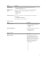
Notes, cautions, and warnings
NOTE: A NOTE indicates important information that helps you make better use of your computer.
CAUTION: A CAUTION indicates either potential damage to hardware or loss of data and tells you
how to avoid the problem.
WARNING: A WARNING indicates a potential for property damage, personal injury, or death.
Copyright © 2015 Dell Inc. All rights reserved. This product is protected by U.S. and international copyright and
intellectual property laws. Dell™ and the Dell logo are trademarks of Dell Inc. in the United States and/or other
jurisdictions. All other marks and names mentioned herein may be trademarks of their respective companies.
2014–09
Rev. A00
Contents
1 Working on Your Computer................................................................................6
Before Working Inside Your Computer................................................................................................ 6
Turning Off Your Computer..................................................................................................................7
After Working Inside Your Computer................................................................................................... 8
2 Removing and Installing Components............................................................. 9
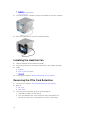
Recommended Tools............................................................................................................................9
System Overview................................................................................................................................... 9
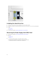
Removing the Power Supply Unit (PSU)............................................................................................. 12
Installing the Power Supply Unit (PSU)............................................................................................... 13
Removing the Front Cover..................................................................................................................13
Installing the Front Cover....................................................................................................................14
Removing the Hard Drive....................................................................................................................14
Installing the Hard Drive...................................................................................................................... 17
Removing the Left Cover.....................................................................................................................17
Installing the Left Cover...................................................................................................................... 18
Removing the Intrusion Switch...........................................................................................................18
Installing the Intrusion Switch.............................................................................................................19
Removing the PCI Card.......................................................................................................................19
Installing the PCI Card........................................................................................................................ 20
Removing the Slimline Optical Drive................................................................................................. 20
Installing the Slimline Optical Drive....................................................................................................23
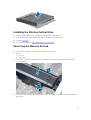
Removing the Memory Shroud.......................................................................................................... 23
Installing the Memory Shroud............................................................................................................ 24
Removing the Memory....................................................................................................................... 25
Installing the Memory......................................................................................................................... 25
Removing the Coin-Cell Battery........................................................................................................ 25
Installing the Coin-Cell Battery.......................................................................................................... 26
Removing the Heatsink.......................................................................................................................26
Installing the Heatsink......................................................................................................................... 27
Removing the Liquid Cooler Heatsink (Optional)..............................................................................28
Installing the Liquid Cooler Heatsink (Optional)................................................................................29
Removing the HeatSink Fan................................................................................................................ 31
Installing the Heatsink Fan.................................................................................................................. 32
Removing the PCIe Card Retention................................................................................................... 32
Installing the PCIe card retention.......................................................................................................33
Removing the System-Fan Assembly.................................................................................................33
Installing the System-Fan Assembly...................................................................................................38
3
Removing the Front Bezel.................................................................................................................. 38
Installing the Front Bezel.................................................................................................................... 39
Removing the I/O Panel and the USB 3.0 Ports................................................................................ 40
Installing the I/O Panel and the USB 3.0 Ports...................................................................................41
Removing the Power Switch.............................................................................................................. 42
Installing the Power Switch................................................................................................................ 43
Removing the Speaker........................................................................................................................ 43
Installing the Speaker..........................................................................................................................44
Removing the Right Cover..................................................................................................................45
Installing the Right Cover................................................................................................................... 46
Removing the 5.25-inch Optical Drive.............................................................................................. 46
Installing the 5.25-inch Optical Drive.................................................................................................47
Removing the HDD Thermal Sensor.................................................................................................. 47
Installing the HDD Thermal Sensor....................................................................................................49
Removing the Processor.................................................................................................................... 49
Installing the Processor...................................................................................................................... 50
Removing the Hard-Drive Fan............................................................................................................50
Installing the Hard-Drive Fan..............................................................................................................52
Removing the Power Supply Unit (PSU) Card....................................................................................52
Installing the Power Supply Unit (PSU) Card......................................................................................53
System Board Components................................................................................................................53
Removing the System Board.............................................................................................................. 55
Installing the System Board.................................................................................................................57
3 Additional Information...................................................................................... 58
Memory Module Guidelines............................................................................................................... 58
Front Panel Chassis Lock.................................................................................................................... 58
Power Supply Unit (PSU) Lock............................................................................................................59
4 System Setup.......................................................................................................60
Boot Sequence....................................................................................................................................60
Navigation Keys...................................................................................................................................60
System Setup Options......................................................................................................................... 61
Updating the BIOS ............................................................................................................................. 69
System and Setup Password...............................................................................................................69
Assigning a System Password and Setup Password.................................................................... 70
Deleting or Changing an Existing System and/or Setup Password.............................................70
Disabling a System Password........................................................................................................ 71
5 Diagnostics...........................................................................................................72
Enhanced Pre-Boot System Assessment (ePSA) Diagnostics............................................................72
4
6 Troubleshooting Your Computer.................................................................... 73
Diagnostic LEDs...................................................................................................................................73
Error Messages.................................................................................................................................... 75
Errors That Halt Your Computer Completely...............................................................................75
Errors That Do Not Halt Your Computer......................................................................................76
Errors That Soft Halt Your Computer........................................................................................... 76
7 Technical Specifications....................................................................................78
8 Contacting Dell...................................................................................................84
5
Working on Your Computer
1
Before Working Inside Your Computer
Use the following safety guidelines to help protect your computer from potential damage and to help to
ensure your personal safety. Unless otherwise noted, each procedure included in this document assumes
that the following conditions exist:
•
You have read the safety information that shipped with your computer.
•
A component can be replaced or--if purchased separately--installed by performing the removal
procedure in reverse order.
WARNING: Disconnect all power sources before opening the computer cover or panels. After you
finish working inside the computer, replace all covers, panels, and screws before connecting to
the power source.
WARNING: Before working inside your computer, read the safety information that shipped with
your computer. For additional safety best practices information, see the Regulatory Compliance
Homepage at www.dell.com/regulatory_compliance
CAUTION: Many repairs may only be done by a certified service technician. You should only
perform troubleshooting and simple repairs as authorized in your product documentation, or as
directed by the online or telephone service and support team. Damage due to servicing that is
not authorized by Dell is not covered by your warranty. Read and follow the safety instructions
that came with the product.
CAUTION: To avoid electrostatic discharge, ground yourself by using a wrist grounding strap or
by periodically touching an unpainted metal surface, such as a connector on the back of the
computer.
CAUTION: Handle components and cards with care. Do not touch the components or contacts
on a card. Hold a card by its edges or by its metal mounting bracket. Hold a component such as a
processor by its edges, not by its pins.
CAUTION: When you disconnect a cable, pull on its connector or on its pull-tab, not on the cable
itself. Some cables have connectors with locking tabs; if you are disconnecting this type of cable,
press in on the locking tabs before you disconnect the cable. As you pull connectors apart, keep
them evenly aligned to avoid bending any connector pins. Also, before you connect a cable,
ensure that both connectors are correctly oriented and aligned.
NOTE: The color of your computer and certain components may appear differently than shown in
this document.
To avoid damaging your computer, perform the following steps before you begin working inside the
computer.
1.
Ensure that your work surface is flat and clean to prevent the computer cover from being scratched.
2.
Turn off your computer (see Turning Off Your Computer).
6
CAUTION: To disconnect a network cable, first unplug the cable from your computer and
then unplug the cable from the network device.
3.
Disconnect all network cables from the computer.
4.
Disconnect your computer and all attached devices from their electrical outlets.
5.
Press and hold the power button while the computer is unplugged to ground the system board.
6.
Remove the cover.
CAUTION: Before touching anything inside your computer, ground yourself by touching an
unpainted metal surface, such as the metal at the back of the computer. While you work,
periodically touch an unpainted metal surface to dissipate static electricity, which could
harm internal components.
Turning Off Your Computer
CAUTION: To avoid losing data, save and close all open files and exit all open programs before
you turn off your computer.
1.
Shut down the operating system:
•
In Windows 8.1:
– Using a touch-enabled device:
a.
Swipe in from the right edge of the screen, opening the Charms menu and select
Settings.
b.
Select the
and then select Shut down.
Or
*
On the Home screen, touch the
and then select Shut down.
– Using a mouse:
a.
Point to upper-right corner of the screen and click Settings.
b.
Click the
and select Shut down.
Or
*
•
On the Home screen, click
and then select Shut down.
In Windows 7:
1.
Click Start
.
2.
Click Shut Down.
or
1.
Click Start
.
7
2.
2.
Click the arrow in the lower-right corner of the Start menu as shown below, and then click
Shut Down
.
Ensure that the computer and all attached devices are turned off. If your computer and attached
devices did not automatically turn off when you shut down your operating system, press and hold
the power button for about 6 seconds to turn them off.
After Working Inside Your Computer
After you complete any replacement procedure, ensure you connect any external devices, cards, and
cables before turning on your computer.
1.
Replace the cover.
CAUTION: To connect a network cable, first plug the cable into the network device and then
plug it into the computer.
2.
Connect any telephone or network cables to your computer.
3.
Connect your computer and all attached devices to their electrical outlets.
4.
Turn on your computer.
5.
If required, verify that the computer works correctly by running the Dell Diagnostics.
8
Removing and Installing Components
2
This section provides detailed information on how to remove or install the components from your
computer.
Recommended Tools
The procedures in this document may require the following tools:
•
Small slotted-tip screwdriver
•
#2 Phillips screwdriver
•
#1 Phillips screwdriver
•
Small plastic scribe
For how-to videos, documentation, and troubleshooting solutions, scan this QR code, or click
here:http://www.Dell.com/QRL/Workstation/T7910
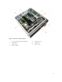
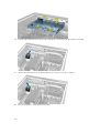
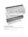
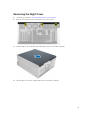
System Overview
Figure 1. Front and Back View of T7910 Computer
9
1.
power button/power light
2.
USB 3.0 connector
3.
optical drive (optional)
4.
optical-drive eject button (optional)
5.
USB 2.0 connectors
6.
hard-drive activity light
7.
microphone connector
8.
headphone connector
9.
optical-drive eject button (optional)
10. optical drive (optional)
11.
line-in/microphone connector
12. serial connector
13. power supply unit (PSU) release latch
14. power cable connector
15. hard-drive access cover release latch
16. USB 3.0 connectors
17. USB 2.0 connectors
18. expansion card slots
19. security cable slot
20. padlock ring
21. line-out connector
22. network connector
23. PS/2 Keyboard connector
24. PS/2 Mouse connector
25. active expansion card slots
26. mechanical slot
10
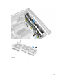
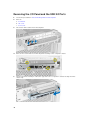
Figure 2. Inside View of T7910 Computer
1.
processor heatsink with integrated fan
2.
memory shroud
3.
optical drive
4.
front bezel
5.
system board
6.
graphics card
7.
intrusion switch
11
Figure 3. Inside View of T7910 Computer
1.
system fans
2.
speaker
3.
PCIe-card retention
4.
power-supply unit
5.
PCIe-card retention
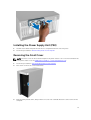
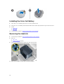
Removing the Power Supply Unit (PSU)
1.
Follow the procedures in Before Working Inside Your Computer.
2.
If the PSU is locked, remove the screw to unlock the PSU. For more information, see the PSU Lock
Feature.
3.
Press and hold the blue tab, then pull the power supply unit away from the computer.
12
Installing the Power Supply Unit (PSU)
1.
Hold the PSU handle and push the unit into its compartment until it clicks into place.
2.
Follow the procedures in After Working Inside Your Computer.
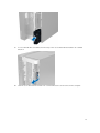
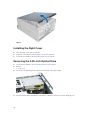
Removing the Front Cover
NOTE: The front cover can be secured using the front panel-chassis lock. For more information the
front-panel chassis lock, see Additional Information — Front Panel Chassis Lock.
1.
Follow the procedures in Before Working Inside Your Computer.
2.
Press down on the front cover release latch.
3.
Keep the latch pushed down, and pull the front cover in an outward direction to remove it from the
computer.
13
Installing the Front Cover
1.
Place the front cover on the computer.
2.
Press down on the front cover till it clicks into place.
3.
Follow the procedures in After Working Inside Your Computer.
Removing the Hard Drive
1.
Follow the procedures inBefore Working Inside Your Computer.
2.
Remove the front cover.
3.
Pull the clasp of the hard-drive bracket in an outward direction.
4.
Slide the hard-drive bracket in an outward direction to remove it from the computer.
14
5.
If a second hard drive is installed, Pull the clasp of the second hard-drive bracket in an outward
direction.
6.
Slide the second hard-drive bracket in an outward direction to remove it from the computer.
15
7.
Flex the hard-drive bracket on both sides to loosen the hard drive.
8.
Lift the hard drive in an upward direction to remove it from the hard-drive bracket.
9.
If a 2.5 inch hard drive is installed , Push the retention clips in an outward direction and lift up the
drive to remove it from the 3.5 inch hard-drive caddy.
16
Installing the Hard Drive
1.
If a 2.5–inch or 3.5–inch hard drive is installed, place the hard drive to the hard-drive caddy until it
snaps to its place.
2.
Flex the hard-drive bracket and then insert the hard drive into the bracket.
3.
Slide the hard-drive bracket into its compartment and close the hard-drive bracket clasp.
4.
Install the front cover.
5.
Follow the procedures in After Working Inside Your Computer.
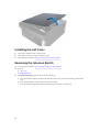
Removing the Left Cover
1.
Follow the procedures in Before Working Inside Your Computer.
2.
Pull up the cover release latch on the side of the computer.
3.
Lift the cover upward to a 45–degree angle and remove it from the computer.
17
Installing the Left Cover
1.
Place the computer cover on the chassis.
2.
Press down on the cover till it clicks into place.
3.
Follow the procedures in After Working Inside Your Computer.
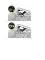
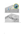
Removing the Intrusion Switch
1.
Follow the procedures in Before Working Inside Your Computer.
2.
Remove:
a. left cover
b. memory shroud
3.
Perform the following steps as shown in the illustration:
a. Press the intrusion switch release latch and disconnect the connector from the system board
[1,2].
b. Unroute the intrusion switch cable from the chassis [3].
c. Push the intrusion switch downwards and remove it from the computer [4].
18
Installing the Intrusion Switch
1.
Install the intrusion switch into its place holder on the chassis.
2.
Route the intrusion-switch cable around the chassis clips and install the connector to the system
board.
3.
Install:
a. memory shroud
b. left cover
4.
Follow the procedures in After Working Inside Your Computer.
Removing the PCI Card
1.
Follow the procedures in Before Working Inside Your Computer.
2.
Remove the left cover.
3.
Open the plastic latch fastening the PCI card in its slot.
19
4.
Press down the latch and pull the PCI card away from the computer.
Installing the PCI Card
1.
Push the expansion card into the card slot and secure the latch.
2.
Install the plastic latch that secures the PCI card to the card slot.
3.
Install the left cover.
4.
Follow the procedures in After Working Inside Your Computer.
Removing the Slimline Optical Drive
1.
Follow the procedures in Before Working Inside Your Computer.
2.
Remove the left cover.
3.
Disconnect the data cable from the back of the optical drive.
20
4.
Disconnect the power cable from the back of the optical drive.
5.
Pull up the blue release tab to release the latches that secure the optical drive.
21
6.
Slide the optical drive out of its compartment and lift it up to remove it from the computer.
7.
Flex the optical-drive bracket latches in an outward direction to loosen the optical drive from the
bracket.
8.
Lift the optical drive and remove it from the bracket.
22
Installing the Slimline Optical Drive
1.
Slide the optical drive into its compartment and ensure it is seated firmly.
2.
Connect the power cable and the data cable to the back of the optical drive.
3.
Install the left cover.
4.
Follow the procedures in After Working Inside Your Computer.
Removing the Memory Shroud
1.
Follow the procedures in Before Working Inside Your Computer.
2.
Remove:
a. left cover
b. optical drive
3.
Press down on the blue retaining tabs on each side of the memory shroud and lift the memory
shroud upwards.
4.
Press down on the release latch on the other side of the memory shroud module to release it from
the chassis.
23
5.
Press down on the release latch on the memory shroud base and lift it upwards to remove it from the
computer.
6.
Repeat the steps to remove the second memory shroud module and memory shroud base from the
computer.
Installing the Memory Shroud
1.
Install the memory shroud base inside the computer chassis.
2.
Mount the memory shroud module on the base and press downwards until it clicks into place.
3.
Install:
a. optical drive
b. left cover
4.
24
Follow the procedures in After Working Inside Your Computer.
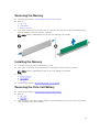
Removing the Memory
1.
Follow the procedures in Before Working Inside Your Computer.
2.
Remove:
a. left cover
b. optical drive
c. memory shroud
3.
Press down on the memory-securing clips on each side of the memory module, and lift the memory
module upwards to remove it from the computer.
NOTE: Tilting of DIMM during removal can cause damage to the DIMM.
Installing the Memory
1.
Insert the memory module into the memory socket.
2.
Press down on the memory module until the securing clips secure the memory in place.
NOTE: Tilting of DIMM during insertion can cause damage to the DIMM.
3.
Install:
a. memory shroud
b. optical drive
c. left cover
4.
Follow the procedures in After Working Inside Your Computer.
Removing the Coin-Cell Battery
1.
Follow the procedures in Before Working Inside Your Computer.
2.
Remove:
a. left cover
b. PCIe card
3.
Press the release latch away from the battery to allow the battery to pop-up from the socket. Lift the
coin-cell battery out of the computer.
25
Installing the Coin-Cell Battery
1.
Place the coin-cell battery into the slot on the system board.
2.
Press the coin-cell battery downward until the release latch springs back into place and secures it.
3.
Install:
a. PCIe card
b. left cover
4.
Follow the procedures in After Working Inside Your Computer.
Removing the Heatsink
1.
Follow the procedures in Before Working Inside Your Computer.
2.
Remove:
a. left cover
b. memory shroud (center)
3.
Disconnect the heatsink fan cable from the system board.
4.
Remove the captive screws that secure the heatsink.
26
5.
Lift up the heatsink and remove it from the computer.
Installing the Heatsink
1.
Place the heatsink inside the computer.
2.
Tighten the captive screws to secure the heatsink to the system board.
NOTE: Misalignment of screws can damage the system.
3.
Connect the heatsink cable to the system board.
4.
Install:
a. memory shroud (center)
b. left cover
5.
Follow the procedures in After Working Inside Your Computer.
27
Removing the Liquid Cooler Heatsink (Optional)
1.
Follow the procedures in Before Working Inside Your Computer.
2.
Remove:
a. left cover
b. memory shroud (center)
3.
Press firmly on the heatsink and rotate anti-clockwise.
4.
Remove the heatsink fan cable from the system board.
5.
Lift the liquid cooler heatsink and remove it from the computer.
28
6.
Remove the screws that secure the heatsink bracket and remove the bracket away from the system
board.
Installing the Liquid Cooler Heatsink (Optional)
1.
Remove all the memory modules.
2.
Install the bracket into the system board and tighten the screws.
29
3.
Place the liquid cooler onto the bracket at 45 degree rotation.
NOTE: The tabs on the bottom of the heatsink must align with the bracket.
4.
30
Connect the heatsink fan cable to the system board.
5.
Press firmly on the heatsink and rotate clockwise.
6.
Install:
a. memory shroud (center)
b. left cover
7.
Install the memory modules.
8.
Follow the procedures in After Working Inside Your Computer.
Removing the HeatSink Fan
1.
Follow the procedures in Before Working Inside Your Computer.
2.
Remove:
a. left cover
31
b. heatsink
c. memory shroud (center)
3.
Push the grommets outward to release the heatsink fan from the assembly.
4.
Remove the heatsink fan from the heatsink assembly.
Installing the Heatsink Fan
1.
Slide the heatsink fan into heatsink assembly.
2.
Plug in the grommets to secure the heatsink fan to the heatsink assembly.
3.
Install:
a. heatsink
b. memory shroud (center)
c. left cover
4.
Follow the procedures in After Working Inside Your Computer.
Removing the PCIe Card Retention
1.
Follow the procedures in Before Working Inside Your Computer.
2.
Remove:
a. left cover
b. PCIe cards
3.
Perform the following steps as shown in the illustration:
a. Unthread the cable from the latch [1].
b. Press and slide the latch out to release the PCIe card retention [2].
c. Lift and remove the PCIe card retention out of the computer [3].
32
Installing the PCIe card retention
1.
Place the PCIe card retention in its slot and insert the latches.
2.
Route the cables through latches.
3.
Install:
a. PCIe cards
b. left cover
4.
Follow the procedures in After Working Inside Your Computer.
Removing the System-Fan Assembly
1.
Follow the procedures in Before Working Inside Your Computer.
2.
Remove:
a.
b.
c.
d.
3.
left cover
optical drive
PCIe card retention
memory shroud
Remove the screws that secure the optical-drive cage.
33
4.
Push the PCIe card retention in the direction indicated to unhinge it from the system-fan module.
5.
Lift the PCIe card retention in an upward direction to remove it from the computer.
6.
Remove the graphics-card cable from the latch.
34
7.
Route the system-fan cable through the opening in the system-fan module.
8.
Perform the following steps as shown in the illustration:
a. Disconnect the system-fan and internal speaker cable connectors from the system board [1,2].
35
9.
Perform the following steps as shown in the illustration:
a. Remove the screws that secure the system-fan assembly to the chassis [1].
b. Lift and remove the system-fan assembly from the chassis [2].
36
10. Insert the fan cable through the opening to release the system-fan module.
11. Remove the grommets that secure the system fan , lift up the fan and remove it from the fan
assembly.
37
Installing the System-Fan Assembly
1.
Tighten the grommets that secure the system fan to the system-fan module.
2.
Connect the system-fan cable to the system-fan module.
3.
Install the screws that secure the system-fan module to the chassis.
4.
Route the system-fan cables out of the opening in the system-fan module in the direction of the
system board.
5.
Connect the system-fan and internal speaker cables to their connectors on the system board.
6.
Slide the memory shroud retention modules downwards into the retention tabs until they are
secured to the system-fan module.
7.
Install the screws that secure the optical-drive bracket to the chassis.
8.
Install:
a.
b.
c.
d.
9.
memory shroud
PCIe card retention
optical drive
left cover
Follow the procedures in After Working Inside Your Computer.
Removing the Front Bezel
1.
Follow the procedures in Before Working Inside Your Computer.
2.
Remove the left cover.
3.
Pry the front bezel retention clips away from the chassis located at the edge of front bezel.
38
4.
Rotate and pull the bezel panel away from the computer to release the hooks on the opposite edge
of the bezel from the chassis.
Installing the Front Bezel
1.
Insert the hooks along the bottom edge of the front panel into the slots on the chassis front.
2.
Rotate the bezel towards the computer to engage the front-bezel retention clips until they click into
place.
3.
Install the left cover.
4.
Follow the procedures in After Working Inside Your Computer.
39
Removing the I/O Panel and the USB 3.0 Ports
1.
Follow the procedures in Before Working Inside Your Computer.
2.
Remove:
a. front bezel
b. left cover
c. front cover
3.
Disconnect all the cables from the I/O panel.
4.
Remove the screws that secure the I/O panel assembly to the computer chassis.
5.
Pull the I/O panel assembly in a direction opposite to the computer to release its edge from the
chassis clip.
40
6.
Slide the opposite edge of the I/O panel assembly outward to disengage the I/O assembly from the
chassis.
7.
Remove the screws that secure the USB 3.0 module to the I/O panel assembly and remove it from
the computer.
8.
Remove the screws that secure the I/O panel and remove it from the I/O panel assembly.
Installing the I/O Panel and the USB 3.0 Ports
1.
Place the I/O panel and install the screws to secure it in place.
2.
Place the USB 3.0 module on the I/O panel assembly and install the screws to secure it in place.
3.
Re-seat the I/O panel assembly on the chassis and secure it to the chassis clips on both sides.
41
4.
Install the screws that secure the I/O panel assembly to the chassis.
5.
Connect all the cables to the I/O panel.
6.
Install:
a. front bezel
b. front cover
c. left cover
7.
Follow the procedures in After Working Inside Your Computer.
Removing the Power Switch
1.
Follow the procedures in Before Working Inside Your Computer.
2.
Remove:
a.
b.
c.
d.
3.
left cover
front cover
front bezel
I/O panel
Perform the following steps:
a. Disconnect the power switch cable from the I/O panel board.
b. Press down on the power switch module on the sides to release the power switch from its
compartment [1,2].
4.
42
Remove the power switch from the computer.
Installing the Power Switch
1.
Connect the power-switch cable to the I/O panel board.
2.
Route the power-switch module through the opening on the front panel.
3.
Press the retention tab to secure the power switch in place.
4.
Install:
a.
b.
c.
d.
5.
I/O panel
front bezel
front cover
left cover
Follow the procedures in After Working Inside Your Computer.
Removing the Speaker
1.
Follow the procedures in Before Working Inside Your Computer.
2.
Remove the left cover.
3.
Disconnect the speaker cable from the system board and unroute it from the securing clip on the
chassis.
43
4.
Perform the following steps:
a. Press the speaker latch on both sides to release the speaker from the chassis.
b. Lift to remove the speaker from the computer.
c. Remove the speaker cable through the opening.
Installing the Speaker
1.
Install the speaker and route the speaker cable through the chassis.
2.
Connect the speaker cable to the system board.
3.
Install the left cover.
4.
Follow the procedures in After Working Inside Your Computer.
44
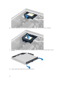
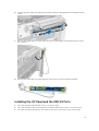
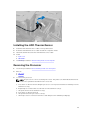
Removing the Right Cover
1.
Follow the procedures in Before Working Inside Your Computer.
2.
Remove the screws that secure the right cover to the chassis.
3.
Slide the right cover in the direction indicated to remove it from the computer.
4.
Lift the right cover at a 45–degree and remove it from the computer.
45
Figure 4.
Installing the Right Cover
1.
Place the right cover on the computer.
2.
Install the screws that secure the right cover to the computer.
3.
Follow the procedures in After Working Inside Your Computer.
Removing the 5.25-inch Optical Drive
1.
Follow the procedures in Before Working Inside Your Computer.
2.
Remove:
a. right cover
3.
Disconnect the data and power cables from the back of the optical drive.
4.
Press the release latch and slide the optical drive outward to release it from the drive bay [1, 2].
46
5.
Remove the screws from the optical drive and remove the bracket.
Installing the 5.25-inch Optical Drive
NOTE: If the sytem is not shipped with optical drive, remove the 5.25-inch optical drive cover from
the front cover to install the Optical drive.
1.
Place the optical drive on the bracket and tighten the screws to secure the optical drive.
2.
Slide the optical drive into the drive bay.
3.
Connect the power and data cables to the optical drive.
4.
Install:
a. right cover
5.
Follow the procedures in After Working Inside Your Computer.
Removing the HDD Thermal Sensor
1.
Follow the procedures in Before Working Inside Your Computer.
2.
Remove:
a. left cover
b. right cover
3.
Perform the following steps:
a. Disconnect the HDD thermal-sensor cable from the system board [1].
b. Unroute the HDD thermal-sensor cable through the chassis opening [2].
47
4.
Unroute the HDD thermal-sensor cable from its securing clips on the chassis.
5.
Open the latch securing the HDD thermal sensor and remove it from the computer.
48
Installing the HDD Thermal Sensor
1.
Install the HDD thermal-sensor cable on the system board.
2.
Route the HDD thermal-sensor cable around the computer chassis.
3.
Fasten the latch that secures the HDD thermal-sensor cable.
4.
Install:
a. right cover
b. left cover
5.
Follow the procedures in After Working Inside Your Computer.
Removing the Processor
1.
Follow the procedures inBefore Working Inside Your Computer.
2.
Remove:
a. left cover
b. heatsink
3.
To remove the processor:
NOTE: The processor cover is secured by two levers. They have icons that indicate which lever
needs to be opened first and which lever closes first.
a. Press down on the first lever holding the processor cover in place and release it sideways from its
retention hook [1].
b. Repeat step 'a' to release the second lever from its retention hook [2].
c. Lift up the lever from its retention hook [3].
d. Press down on the first lever [4].
e. Lift up and remove the processor cover [5].
f. Lift the processor to remove it from the socket and place it in antistatic package [6].
49
NOTE: Damaging pins during removal of the processor can cause damage to the processor.
4.
Repeat the above steps to remove the second processor (if available) from the computer.
To verify if your computer has dual processor slots, see the System Board components.
Installing the Processor
1.
Place the processor in its socket.
2.
Replace the processor cover.
NOTE: The processor cover is secured by two levers. They have icons that indicate which lever
needs to be opened first and which lever closes first.
3.
Slide the first lever sideways into the retention hook to secure the processor.
4.
Repeat step '3' to slide the second lever into the retention hook.
5.
Install:
a. heatsink
b. left cover
6.
Follow the procedures in After Working Inside Your Computer.
Removing the Hard-Drive Fan
1.
Follow the procedures in Before Working Inside Your Computer.
2.
Remove:
a. left cover
50
b. right cover
3.
Disconnect the hard-drive fan cable from the system board.
4.
Route the cable from below the computer chassis as indicated.
5.
Remove the screws that secure the hard-drive fan to the computer chassis and remove the fan from
the computer.
51
Installing the Hard-Drive Fan
1.
Install the screws that secure the hard-drive fan to the system chassis.
2.
Route the hard-drive fan cable through the chassis and connect it to its slot on the system board.
3.
Install:
a. left cover
b. right cover
4.
Follow the procedures in After Working Inside Your Computer.
Removing the Power Supply Unit (PSU) Card
1.
Follow the procedures in Before Working Inside Your Computer.
2.
Remove:
a. right cover
b. PSU
3.
52
a. Disconnect all the cables connected to the PSU card [1].
b. Remove the screws that secure the PSU card to the chassis [2].
c. Lift and remove the PSU card from the computer [3].
Installing the Power Supply Unit (PSU) Card
1.
Install the screws that secure the PSU card to the chassis.
2.
Connect all the cables to the PSU card.
3.
Install:
a. PSU
b. right cover
4.
Follow the procedures in After Working Inside Your Computer.
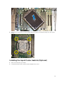
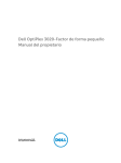
System Board Components
The following image displays the system board components .
53
1.
PCI card slot (slot 5)
2.
PCI Express 3.0 x16 card slot (slot 4)
3.
PCI Express 2.0 x16 (x4 electrically) card slot
(slot 3)
4.
PCI Express 3.0 x16 card slot (slot 2)
5.
PCI Express 3.0 x16 (x4 electrically) card slot
(slot 1)
6.
intrusion-switch connector
7.
DIMM slots (available only when optional
second processor is installed)
8.
processor socket
9.
CPU2 fan connector
10.
front-panel audio connector
11.
DIMM slots (available only when optional
second processor is installed)
12.
PCI Express 3.0 x16 slots (available only
when optional second processor is installed)
(CPU2_SLOT1 and CPU2_SLOT2)
13.
coin-cell battery
14.
HDD3 fan connector
15.
CPU power connector
16.
HDD2 fan connector
17.
CPU power connector
18.
system fan connector
19.
DIMM slots
20.
processor socket
21.
DIMM slots
22.
remote power connector
23.
thunderbolt side band connector
24.
system fan connector
25.
system fan connector
26.
internal speaker connector
27.
integrated SAS0 connector
28.
integrated SAS1 connector
29.
main power connector
30.
CMOS Clear Jumper
54
31.
password jumper
32.
hard-drive fan connector
33.
SATA connectors
34.
USB 3.0 connector for front panel
35.
CPU1 fan connector
36.
front panel connector
37.
thermal sensor connector
38.
internal USB 2.0 connector
39.
HDD1 fan connector
Removing the System Board
1.
Follow the procedures in Before Working Inside Your Computer.
2.
Remove the:
a.
b.
c.
d.
e.
f.
g.
h.
i.
j.
left cover
optical drive holder
optical drive
memory shroud base (s)
memory shrouds
heatsink
PCIe card retention
PCIe card (s)
memory module (s)
processor
3.
Disconnect all the connectors from the system board.
4.
Remove the screws that secure the system board to the chassis.
55
5.
Perform the following steps as shown in the illustration:
a. Slide the system board towards front direction [1].
b. Tilt the system board [2].
6.
56
Lift the system board in an upward direction and remove it from the computer.
Installing the System Board
1.
Align the system board to the port connectors on the back of the chassis and place the system board
in the chassis.
2.
Tighten the screws that secure the system board to the chassis.
3.
Connect the connectors to the system board.
4.
Install the:
a.
b.
c.
d.
e.
f.
g.
h.
i.
j.
5.
processor
memory module(s)
PCIe card retention
PCIe card(s)
heatsink
memory shroud base
memory shrouds
optical drive holder
optical drive
left cover
Follow the procedures in After Working Inside Your Computer.
57
Additional Information
3
This section provides information for the additional features that are part of your computer.
Memory Module Guidelines
To ensure optimal performance of your computer, observe the following general guidelines when
configuring your system memory:
•
Memory modules of different sizes can be mixed (for example, 2 GB and 4 GB). But, all populated
channels must have identical configurations.
•
Memory modules must be installed beginning with the first socket.
NOTE: Registered DIMMS (R-DIMMs) and Load Reduced DIMMS (LR-DIMMs) cannot be mixed.
•
If memory modules with different speeds are installed, they operate at the speed of the slowest
installed memory modules.
NOTE: If all DIMMs are 2133, the CPU ordered may run the memory at a slower speed.
Front Panel Chassis Lock
The front panel chassis lock allows you to lock the front panel. The lock is located inside the chassis. It
consists of two buttons:
•
orange button — press this button to lock the front panel.
•
green button — press this button to unlock the front panel.
NOTE: To lock or unlock the front panel chassis, always ensure that the left cover of the chassis is
removed. For information on removing the left cover, see Removing Left Cover.
58
Power Supply Unit (PSU) Lock
The PSU lock prevents the removal of the PSU from the chassis.
NOTE: To lock or unlock the PSU, always ensure that the cover of the chassis is removed.
To secure the PSU, remove the screw from the unlock screw location and tighten the screw to the lock
location. Similarly, to unlock the PSU, remove the screw from the lock screw location and tighten the
screw to the unlock screw location.
59
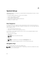
System Setup
4
System Setup enables you to manage your computer hardware and specify BIOS‐level options. From the
System Setup, you can:
•
Change the NVRAM settings after you add or remove hardware
•
View the system hardware configuration
•
Enable or disable integrated devices
•
Set performance and power management thresholds
•
Manage your computer security
Boot Sequence
Boot Sequence allows you to bypass the System Setup‐defined boot device order and boot directly to a
specific device (for example: optical drive or hard drive). During the Power-on Self Test (POST), when the
Dell logo appears, you can:
•
Access System Setup by pressing <F2> key
•
Bring up the one-time boot menu by pressing <F12> key
The one-time boot menu displays the devices that you can boot from including the diagnostic option.
The boot-menu options are:
•
Removable Drive (if available)
•
STXXXX Drive
NOTE: XXX denotes the SATA drive number.
•
Optical Drive
•
Diagnostics
NOTE: Choosing Diagnostics, will display the ePSA diagnostics screen.
The boot sequence screen also displays the option to access the System Setup screen.
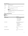
Navigation Keys
The following table displays the system setup navigation keys.
NOTE: For most of the system setup options, changes that you make are recorded but do not take
effect until you re-start the system.
60
Table 1. Navigation Keys
Keys
Navigation
Up arrow
Moves to the previous field.
Down arrow
Moves to the next field.
<Enter>
Allows you to select a value in the selected field (if applicable) or follow the link in
the field.
Spacebar
Expands or collapses a drop‐down list, if applicable.
<Tab>
Moves to the next focus area.
NOTE: For the standard graphics browser only.
<Esc>
Moves to the previous page till you view the main screen. Pressing <Esc> in the main
screen displays a message that prompts you to save any unsaved changes and
restarts the system.
<F1>
Displays the System Setup help file.
System Setup Options
NOTE: Depending on your computer and its installed devices, the items listed in this section may or
may not appear.
Table 2. General
Option
Description
System Information
This section lists the primary hardware
features of your computer.
•
•
•
•
•
Boot Sequence
Allows you to change the order in which
the computer attempts to find an
operating system.
•
•
•
•
•
Boot List Option
Diskette Drive
USB Storage Device
CD/DVD/CD-RW Drive
Onboard NIC
Internal HDD
Allows you to change the boot list
option.
•
•
Advanced Boot Options
System Information
Memory Configuration
Processor Information
Device Information
PCI Information
Legacy
UEFI
Allows you to Enable Legacy Option
ROMs
61
Option
Description
•
Date/Time
Enable Legacy Option ROMs
(Default)
Allows you to set the date and time. The
changes to the system date and time
takes effect immediately.
Table 3. System Configuration
Option
Description
Integrated NIC
Allows you to configure the integrated network controller. The
options are:
Integrated NIC 2
•
•
Enable UEFI Network Stack
Disabled
•
•
NOTE: You can use the Disabled option, only if Active
Management Technology (AMT) option is disabled.
Enabled
Enabled w/PXE (Default)
Allows you to configure the
integrated network controller. The
options are:
•
•
Enabled (Default)
Enabled w/PXE
NOTE: This feature is supported
only on Tower 7910.
Serial Port
Identifies and defines the serial port settings. You can set the
serial port to:
•
•
•
•
•
Disabled
COM1 (Default)
COM2
COM3
COM4
NOTE: The operating system may allocate resources even if
the setting is disabled.
SATA Operation
Tower 7910
Allows you to configure the internal SATA hard-drive controller.
The options are:
•
•
•
Disabled
ATA
AHCI (Default)
NOTE: SATA is configured to support RAID mode. No SATA
operation support in Tower 7910.
Drives
62
Option
Description
Tower 7910
•
•
SATA–0
SATA–1
Default Setting: All drives are enabled.
NOTE: If the hard drives are connected to a RAID controller
card, the hard drives will display {none} in all the fields. The
hard drives can be seen in the RAID controller card BIOS.
SMART Reporting
This field controls if the hard drive errors for the integrated
drives are reported during system startup. This technology is
part of the SMART (Self Monitoring Analysis and Reporting
Technology) specification.
•
USB Configuration
Allows you to enable or disable the internal USB configuration.
The options are:
•
•
•
•
SAS RAID Controller (Tower 7910
only)
Audio
Allows you enable or disable the audio feature.
Enabled
Disabled (Default)
Allows you to enable or disable
various on board devices.
•
PCI MMIO Space Size
Memory Map IO above 4GB - This
option is disabled by default.
Allows you to enable or disable Thunderbolt device support
capability.
•
•
Miscellaneous devices
Enable Audio (Default)
Allows you enable or disable Memory
Map IO above 4GB.
•
Thunderbolt
Enabled (Default)
Disabled.
Allows you to control the HDD fans.
Default Setting: depends on the system configuration
•
Memory Map IO above 4GB
Enable Boot Support
Enable Front USB Ports
Enable internal USB ports
Enable rear USB Ports
Allows you to control the operation
of the integrated SAS RAID HDD
controller.
•
•
HDD Fans
Enable SMART Reporting - This option is disabled by default.
Enable PCI Slot
This field controls the balance of 32bit memory available between PCI
63
Option
Description
(memory-mapped IO) and the
operating system.
•
•
Small (Default)
Large
Table 4. Video
Option
Description
Primary Video Slot
Allows you to configure primary boot
video device. The options are:
•
•
•
•
•
•
•
•
•
Auto (Default)
SLOT 1
SLOT 2: VGA Compatible
SLOT 3
SLOT 4
SLOT 5
SLOT 6 ( Tower 5810 and Tower
7810 only)
SLOT1_CPU2: VGA Compatible
(Tower 7910 only)
SLOT2_CPU2 (Tower 7910 only)
Table 5. Security
Option
Description
Strong Password
Allows you to enforce the option to always set strong passwords.
Default Setting: Enable Strong Password is not selected.
Password
Configuration
You can define the length of your password. Min = 4 , Max = 32
Password Bypass
Allows you to enable or disable the permission to bypass the System password,
when it is set. The options are:
•
•
Disabled (Default)
Reboot bypass
Password Change
Allows you to enable the disable permission to the System passwords when the
administrator password is set.
Default Setting: Allow Non-Admin Password Changes is selected
TPM Security
Allows you to enable the Trusted Platform Module (TPM) during POST.
Default Setting: The option is disabled.
Computrace (R)
Allows you to activate or disable the optional Computrace software. The
options are:
•
•
•
64
Deactivate (Default)
Disable
Activate
Option
Description
CPU XD Support
Allows you to enable the Execute Disable mode of the processor.
•
OROM Keyboard
Access
Enable CPU XD Support (Default)
Allows you to determine whether users are able to enter Option ROM
Configuration screens via hotkeys during boot. The options are:
•
•
•
Enable (Default)
One Time Enable
Disable
Admin Setup Lockout Allows you to prevent users from entering Setup when an administrator
password is set.
•
Enable Admin Setup Lockout
Default Setting: The option is disabled.
Table 6. Secure Boot
Option
Description
Secure Boot Enable
Allows you to enable or disable the
Secure Boot Feature. The options are:
•
•
Expert Key Management
Disabled (Default)
Enabled
Allows you to enable or disable Custom
Mode Key Management.
•
Disabled (Default)
Table 7. Performance
Option
Description
Multi Core Support
This field specifies whether the
processor will have one or all cores
enabled. The performance of some
applications will improve with the
additional cores. This option is enabled
by default. Allows you to enable or
disable multi-core support for the
processor. The options are:
•
•
•
•
•
•
•
•
•
All (Default)
1
2
4
5
6
7
8
9
65
Option
Description
NOTE:
•
•
The options displayed could be
different depending on the
installed processor(s).
The options depend on the
number of cores supported by
the installed processor (All, 1, 2,
N-1 for N-Core Processors)
Intel SpeedStep
Allows you to enable or disable the Intel
SpeedStep feature.
Default Setting: Enable Intel SpeedStep
C States
Allows you to enable or disable the
additional processor sleep states.
Default Setting:Enabled
Limit CPUID Value
This field limits the maximum value the
processor Standard CPUID Function will
support.
•
Enable CPUID Limit
Default Setting: The option is disabled.
Intel TurboBoost
Allows you to enable or disable the Intel
TurboBoost mode of the processor.
Default Setting: Enable Intel
TurboBoost
Hyper-Thread Control
Allows you to enable or disable the
HyperThreading in the processor.
Default Setting: Enabled
Cache Prefetch
Default Setting: Enable Hardware
Prefetch and Adjacent Cache Line
Prefetch
Dell Reliable Memory Technology (RMT)
Allows you to identify and isolate
memory errors in system RAM..
Default Setting: Enable Dell Reliable
Memory Technology (RMT)
Table 8. Power Management
Option
Description
AC Recovery
Specifies how the computer will respond when AC power is applied after a AC
power loss. You can set the AC Recovery to:
•
•
66
Power Off (Default)
Power On
Option
Description
•
Auto On Time
Allows you to set the time at which the computer must turn on automatically.
The options are:
•
•
•
•
Deep Sleep Control
Disabled (Default)
Enabled in S5 only
Enabled in S4 and S5
Allows you to control the speed of the system fan. The options are:
•
•
•
•
•
•
USB Wake Support
Disabled (Default)
Every Day
Weekdays
Select Days
Allows you to define the controls when Deep Sleep is enabled.
•
•
•
Fan Speed Control
Last Power State
Auto (Default)
Medium low
Medium high
Medium
High
Low
Allows you to enable USB devices to wake the system from standby.
•
Enable USB Wake Support
Default Setting: The option is disabled.
Wake on LAN
This option allows the computer to power up from the off state when triggered
by a special LAN signal. Wake-up from the Standby state is unaffected by this
setting and must be enabled in the operating system. This feature only works
when the computer is connected to AC power supply.
•
•
•
Disabled - Does not allow the system to power on by special LAN signals
when it receives a wake-up signal from the LAN or wireless LAN.
LAN Only - Allows the system to be powered on by special LAN signals.
LAN with PXE Boot - Allows the system to power on and immediately boot
to PXE when it receives a wake-up packet sent to the system in either the S4
or S5 state.
This option is Disabled by default.
Block Sleep
Allows you to block entering to sleep (S3 state) in OS Environment.
Default Setting: Disabled
Table 9. POST Behavior
Option
Description
Numlock LED
Specifies if the NumLock function can be enabled when the system boots. This
option is enabled by default.
Keyboard Errors
Specifies whether keyboard related errors are reported when it boots. This
option is enabled by default.
67
Option
Description
Fastboot
Allows you to speed up the boot process by bypassing some compatibility steps.
The options are:
•
•
•
Minimal
Thorough - This option is enabled by default.
Auto
Table 10. Virtualization Support
Option
Description
Virtualization
This option specifies whether a Virtual Machine Monitor (VMM) can utilize the
additional hardware capabilities provided by Intel Virtualization technology.
•
VT for Direct I/O
Enables or disables the Virtual Machine Monitor (VMM) from utilizing the
additional hardware capabilities provided by Intel Virtualization technology for
direct I/O.
•
Trusted Execution
Enable Intel Virtualization Technology - This option is enabled by default.
Enable VT for Direct I/O - This option is enabled by default.
Allows you to specify whether a Measured Virtual Machine Monitor (MVMM) can
utilize the additional hardware capabilities provided by Intel Trusted Execution
Program.
•
Trusted Execution - This option is disabled by default.
Table 11. Maintenance
Option
Description
Service Tag
Displays the service tag of your computer.
Asset Tag
Allows you to create a system asset tag if an asset tag is not already set. This
option is not set by default.
SERR Messages
Controls the SERR message mechanism. This option is not set by default. Some
graphics cards require that the SERR message mechanism be disabled.
Table 12. System Logs
Option
Description
BIOS events
Displays the system event log and allows you to clear the log.
•
Clear Log
Table 13. Engineering Configurations
Option
Description
ASPM
•
•
•
•
68
Auto (Default)
L1 Only
Disabled
L0s and L1
Option
Description
Pcie LinkSpeed
•
L0s Only
•
•
•
•
Auto (Default)
Gen1
Gen2
Gen3
Updating the BIOS
It is recommended to update your BIOS (system setup), on replacing the system board or if an update is
available. For laptops, ensure that your computer battery is fully charged and connected to a power
outlet
1.
Re-start the computer.
2.
Go to dell.com/support.
3.
Enter the Service Tag or Express Service Code and click Submit.
NOTE: To locate the Service Tag, click Where is my Service Tag?
NOTE: If you cannot find your Service Tag, click Detect My Product. Proceed with the
instructions on screen.
4.
If you are unable to locate or find the Service Tag, click the Product Category of your computer.
5.
Choose the Product Type from the list.
6.
Select your computer model and the Product Support page of your computer appears.
7.
Click Get drivers and click View All Drivers.
The Drivers and Downloads page opens.
8.
On the Drivers and Downloads screen, under the Operating System drop-down list, select BIOS.
9.
Identify the latest BIOS file and click Download File.
You can also analyze which drivers need an update. To do this for your product, click Analyze
System for Updates and follow the instructions on the screen.
10. Select your preferred download method in the Please select your download method below
window; click Download File.
The File Download window appears.
11. Click Save to save the file on your computer.
12. Click Run to install the updated BIOS settings on your computer.
Follow the instructions on the screen.
System and Setup Password
You can create a system password and a setup password to secure your computer.
Password Type
Description
System password
Password that you must enter to log on to your system.
Setup password
Password that you must enter to access and make changes to the BIOS settings of
your computer.
69
CAUTION: The password features provide a basic level of security for the data on your computer.
CAUTION: Anyone can access the data stored on your computer if it is not locked and left
unattended.
NOTE: Your computer is shipped with the system and setup password feature disabled.
Assigning a System Password and Setup Password
You can assign a new System Password and/or Setup Password or change an existing System Password
and/or Setup Password only when Password Status is Unlocked. If the Password Status is Locked, you
cannot change the System Password.
NOTE: If the password jumper is disabled, the existing System Password and Setup Password are
deleted and you need not provide the system password to log on to the computer.
To enter a system setup, press <F2> immediately after a power-on or re-boot.
1.
In the System BIOS or System Setup screen, select System Security and press <Enter>.
The System Security screen appears.
2.
In the System Security screen, verify that Password Status is Unlocked.
3.
Select System Password , enter your system password, and press <Enter> or <Tab>.
Use the following guidelines to assign the system password:
•
A password can have up to 32 characters.
•
The password can contain the numbers 0 through 9.
•
Only lower case letters are valid, upper case letters are not allowed.
•
Only the following special characters are allowed: space, (”), (+), (,), (-), (.), (/), (;), ([), (\), (]), (`).
Re-enter the system password when prompted.
4.
Type the system password that you entered earlier and click OK.
5.
Select Setup Password, type your system password and press <Enter> or <Tab>.
A message prompts you to re-type the setup password.
6.
Type the setup password that you entered earlier and click OK.
7.
Press <Esc> and a message prompts you to save the changes.
8.
Press <Y> to save the changes.
The computer reboots.
Deleting or Changing an Existing System and/or Setup Password
Ensure that the Password Status is Unlocked (in the System Setup) before attempting to delete or change
the existing System and/or Setup password. You cannot delete or change an existing System or Setup
password, if the Password Status is Locked.
To enter the System Setup, press <F2> immediately after a power-on or reboot.
1.
In the System BIOS or System Setup screen, select System Security and press <Enter>.
The System Security screen is displayed.
2.
In the System Security screen, verify that Password Status is Unlocked.
3.
Select System Password, alter or delete the existing system password and press <Enter> or <Tab>.
4.
Select Setup Password, alter or delete the existing setup password and press <Enter> or <Tab>.
70
NOTE: If you change the System and/or Setup password, re-enter the new password when
promoted. If you delete the System and/or Setup password, confirm the deletion when
promoted.
5.
Press <Esc> and a message prompts you to save the changes.
6.
Press <Y> to save the changes and exit from the System Setup.
The computer reboots.
Disabling a System Password
The system's software security features include a system password and a setup password. The password
jumper disables any password(s) currently in use. There are 2–pins for the PSWD jumper.
NOTE: The password jumper is disabled by default.
1.
Follow the procedures in Before Working Inside Your Computer.
2.
Remove the cover.
3.
Identify the PSWD jumper on the system board. For identifying the PSWD jumper on the system
board, see the System Board Components.
4.
Remove the PSWD jumper from the system board.
NOTE: The existing passwords are not disabled (erased) until the computer boots without the
jumper.
5.
Install the cover.
NOTE: If you assign a new system and/or setup password with the PSWD jumper installed, the
system disables the new password(s) the next time it boots.
6.
Connect the computer to the electrical outlet and power-on the computer.
7.
Power-off the computer and disconnect the power cable from the electrical outlet.
8.
Remove the cover.
9.
Replace the jumper on the pins.
10. Install the cover.
11. Follow the procedures in After Working Inside Your Computer.
12. Power-on the computer.
13. Go to the system setup, and assign a new system or setup password.
71
Diagnostics
5
If you experience a problem with your computer, run the ePSA diagnostics before contacting Dell for
technical assistance. The purpose of running diagnostics is to test your computer's hardware without
requiring additional equipment or risking data loss. If you are unable to fix the problem yourself, service
and support personnel can use the diagnostics results to help you solve the problem.
Enhanced Pre-Boot System Assessment (ePSA)
Diagnostics
The ePSA diagnostics (also known as system diagnostics) performs a complete check of your hardware.
The ePSA is embedded with the BIOS and is launched by the BIOS internally. The embedded system
diagnostics provides a set of options for particular devices or device groups allowing you to:
•
Run tests automatically or in an interactive mode
•
Repeat tests
•
Display or save test results
•
Run thorough tests to introduce additional test options to provide extra information about the failed
device(s)
•
View status messages that inform you if tests are completed successfully
•
View error messages that inform you of problems encountered during testing
CAUTION: Use the system diagnostics to test only your computer. Using this program with other
computers may cause invalid results or error messages.
NOTE: Some tests for specific devices require user interaction. Always ensure that you are present
at the computer terminal when the diagnostic tests are performed.
1.
Power-on the computer.
2.
As the computer boots, press the <F12> key as the Dell logo appears.
3.
On the boot menu screen, select the Diagnostics option.
The Enhanced Pre-boot System Assessment window is displayed, listing all devices detected in the
computer. The diagnostics starts running the tests on all the detected devices.
NOTE: System may reboot before entering diagnostics depending on the configuration.
4.
If you wish to run a diagnostic test on a specific device, press <Esc> and click Yes to stop the
diagnostic test.
5.
Select the device from the left pane and click Run Tests.
6.
If there are any issues, error codes are displayed.
Note the error code and contact Dell.
72
Troubleshooting Your Computer
6
You can troubleshoot your computer using indicators like Diagnostic Lights, Beep Codes, and Error
Messages during the operation of the computer.
Diagnostic LEDs
NOTE: The diagnostic LEDs only serve as an indicator of the progress through the Power-On Self
Test (POST) process. These LEDs do not indicate the problem that caused the POST routine to stop.
The diagnostic LEDs are located on the front of the chassis next to the power button. These diagnostic
LEDs are only active and visible during the POST process. Once the operating system starts to load, they
turn off and are no longer visible.
Each LED has two possible states of OFF or ON.
NOTE: The diagnostic lights will blink when the power button is amber or off, and will not blink
when it is white.
Table 14. POST Diagnostic LED Patterns
Power LED State
System State
Notes
Off
S5/S4
Normal- System is Off/Hibernate
Blinking White
S3
Normal- System is in Standby/Suspend
Blinking Amber
N/A
Abnormal- PSU cannot turn on, recommend PSU BIST.
Replace PSU.
Steady White
S0
Normal- System is on functioning
Steady Amber
N/A
Abnormal- System cannot turn on, recommend check
motherboard components or replace motherboard.
NOTE: Amber LED blinking scheme pattern is 2 or 3 blinks followed by a short pause then X
number of blinks up to 7. Pattern has a long pause inserted in the middle. For example 2,3 = 2
amber blinks, short pause, 3 amber blinks followed by long pause then repeats.
Table 15. POST Diagnostic LED Patterns
Blink Patter
System State
Notes
2,1
A possible system motherboard
failure has occurred.
Recommend replace
motherboard.
2,2
A possible PSU or cabling issue
has occurred.
Run PSU BIST.
73
Check the PSU cabling to
Motherboard to make sure that
all cables are installed correctly.
2,3
A possible Motherboard,
Memory, or CPU failure has
occurred
2,4
A possible coin cell failure has
occurred.
2,5
System is in Recovery Mode
BIOS checksum failure was
detected and the system is now
in recovery mode.
2,6
A possible processor failure has
occurred
Re-seat the processor
2,7
Memory modules are detected,
but a memory power failure has
occurred.
If two or more memory modules
are installed, remove the
modules, then reinstall one
module and restart the
computer. If the computer starts
normally, continue to install
additional memory modules (one
at a time) until you have
identified a faulty module or
reinstalled all modules without
error.
3,1
PCI device configuration activity
is in progress or PCI device
failure was detected.
Remove all peripheral cards from
the PCI and PCI-E slots and
reboot the computer. If the
computer boots, add the
peripheral cards back one by one
until you find the bad one.
3,2
A possible HDD or USB failure
has occurred.
Re-seat all power and data cables
to HDD’s. Reinstall all USB
devices and check all cable
connections.
3,3
No memory modules installed
If two or more memory modules
are installed, remove the
modules, then reinstall one
module and restart the
computer. If the computer starts
normally, continue to install
additional memory modules (one
74
If two or more memory modules
are installed, remove the
modules, then reinstall one
module and restart the
computer. If the computer starts
normally, continue to install
additional memory modules (one
at a time) until you have
identified a faulty module or
reinstalled all modules without
error.
at a time) until you have
identified all modules without
error. If available, install working
memory of the same type into
your computer.
3,4
Power connector not installed
properly.
Re-seat the 2x2 power
connector from the power
supply unit.
3,5
Memory modules are detected,
but a memory configuration or
compatibility error has occurred.
Ensure that no special
requirements for memory
module or connector placement
exist. Ensure that the memory
you are using is supported by
your computer.
3,6
A possible system board resource Clear CMOS (re-seat the coinand/or hardware failure has
cell battery. See removing and
occurred.
Installing Coin-Cell battery).
3,7
Some other failure has occurred.
Ensure that the display or
monitor is plugged into a discrete
graphics card. Ensure that all
hard drives and optical-drive
cables are properly connected to
the system board. If there is an
error message on the screen
identifying a problem with a
device (such as the floppy drive
or hard drive), check the device
to make sure it is functioning
properly. If the operating system
is attempting to boot from a
device (such as the floppy drive
or optical drive), check system
setup to ensure the boot
sequence is correct for the
devices installed on your
computer.
Error Messages
There are three types of BIOS error messages that are displayed depending on the severity of the issue.
They are:
Errors That Halt Your Computer Completely
These error messages will halt the computer requiring you to cycle the system's power. The following
table lists the error messages.
75
Table 16. Errors that halt your computer completely
Error Message
Error! Non-ECC DIMMs are not supported on this system.
Alert! Processor cache size is mismatched.
Install like processor or one processor.
Alert! Processor type mismatch.
Install like processor or one processor.
Alert! Processor speed mismatch
Install like processor or one processor.
Alert! Incompatible Processor detected.
Install like processor or one processor.
Errors That Do Not Halt Your Computer
These error messages will not halt your computer, but will display a warning message, pause for a few
seconds, and then continue to boot. The following table lists the error messages.
Table 17. Errors that do not halt your computer
Error Message
Alert! Cover was previously removed.
Errors That Soft Halt Your Computer
These error messages will cause a soft halt of your computer and you will be prompted to press <F1> to
continue or <F2 > to enter the system setup. The following table lists the error messages.
Table 18. — Errors that soft halt your computer
Error Message
Alert! Front I/O Cable failure.
Alert! Left Memory fan failure.
Alert! Right Memory fan failure.
Alert! PCI fan failure.
Alert! Chipset heat sink not detected.
Alert! Hard Drive fan1 failure.
Alert! Hard Drive fan2 failure.
Alert! Hard Drive fan3 failure.
Alert! CPU 0 fan failure.
Alert! CPU 1 fan failure.
76
Error Message
Alert! Memory related failure detected.
Alert! Correctable memory error has been detected in memory slot DIMMx.
Warning: Non-optimal memory population detected. For increased memory bandwidth populate DIMM
connectors with white latches before those with black latches.
Your current power supply does not support the recent configuration changes made to your system.
Please contact Dell Technical support team to learn about upgrading to a higher wattage power supply.
Dell Reliable Memory Technology (RMT) has discovered and isolated errors in system memory. You may
continue to work. Memory module replacement is recommended. Please refer to the RMT Event log
screen in BIOS setup for specific DIMM information.
Dell Reliable Memory Technology (RMT) has discovered and isolated errors in system memory. You may
continue to work. Additional errors will not be isolated. Memory module replacement is recommended.
Please refer to the RMT Event log screen in BIOS setup for specific DIMM information.
77
Technical Specifications
7
NOTE: Offerings may vary by region. The following specifications are only those required by law to
ship with your computer. For more information about the configuration of your computer, go to
Help and Support in your Windows operating system and select the option to view information
about your computer.
Table 19. Processor
Feature
Specification
Type
4, 6, 8, 10, 12, 14, 16 and 18 core Intel Xeon processor.
Cache
Instruction Cache
32 KB
Data Cache
•
•
•
32 KB
256 KB Mid-Level Cache per core
Up to 45 MB last level cache (LLC) shared among all cores
(2.5 MB per core)
Table 20. System Information
Feature
Specification
Chipset
Intel(R) C610 , C612 chipset
BIOS chip (NVRAM)
16 MB serial flash EEPROM
Table 21. Memory
Feature
Specification
Memory module connector
16 DIMM slots (8 per CPU)
Memory module capacity
4 GB, 8 GB, and 16 GB RDIMM, and 32 GB LR-DIMM
Type
2133 DDR4 RDIMM and LR-DIMM ECC
Minimum memory
8 GB per CPU
Maximum memory
512 GB
Table 22. Video
Feature
Specification
Discrete (PCIe 3.0/2.0 x16)
up to 4* full-height, full length (maximum of 675 W)
*Requires 2nd CPU
78
Table 23. Audio
Feature
Specification
Integrated
Realtek ALC3220 audio codec
Table 24. Network
Feature
Specification
Tower 7910
Intel i217 and Intel i210
Table 25. Expansion Interfaces
Feature
Specification
PCI:
SLOT1
PCI Express 3.0 x16 (x4 electrical), 16GB/s
SLOT2
PCI Express 3.0 x16, 16GB/s
SLOT3
PCI Express 2.0 x16 (x4 electrical), 16GB/s
SLOT4
PCI Express 3.0 x16, 16GB/s
SLOT5
PCI
CPU2 SLOT1
PCI Express 3.0 x16 (requires second CPU)
CPU2 SLOT2
PCI Express 3.0 x16 (requires second CPU)
Storage (HDD/SSD):
SAS0 4-port mini-SAS
SAS3, 12 Gbps (SATA3, 6 Gbps)
SAS1 4-port mini-SAS
SAS3, 12 Gbps (SATA3, 6 Gbps)
Storage (ODD):
SATA2-ODD0
Intel AHCI SATA 3.0, 6Gbps
SATA2-ODD1
Intel AHCI SATA 3.0, 6 Gbps
USB:
Front ports
USB 3.0, 5 Gbps (1 port)
USB 2.0, 480 Mbps (3 ports)
Rear ports
USB 3.0, 5 Gbps (3 ports)
Internal ports
USB 2.0, 480 Mbps (3 ports)
Table 26. Drives
Feature
Specification
Tower 7910
Externally accessible:
Slimline SATA optical bays
one
5.25–inch drive bays
one:
•
•
supports one 5.25–inches device
supports one media card reader
79
Feature
Specification
•
3.5–inch hard drive bays
supports up to four 2.5–inches hard drives (with optional
adapters)
four
NOTE: These hard drive bays can hold four 2.5–inch hard drive with supplied HDD caddy.
Internally accessible
none
Table 27. External Connectors
Feature
Specification
Audio
•
•
front panel — mic-in, headphone-out
back panel — line-out, mic in/line In
Network
Tower 7910
Serial
two RJ-45 connector
one 9-pin connector
USB
Tower 7910
Video
•
•
•
front panel — three USB 2.0, and one USB 3.0
back panel — three USB 2.0, and one USB 3.0
internal — three USB 2.0
Video card dependent
•
•
•
•
DVI connector
mini DisplayPort
DisplayPort
DMS-59
Table 28. Internal Connectors
Feature
Specification
System power
one 28–pin connector
System fans
three 4-pin connectors
Thunderbolt sideband connector
one 5-pin connector
Processor fans
Tower 7910
two 5-pin connectors
HDD fans
Tower 7910
three 5-pin connectors
Memory
Tower 7910
sixteen 288–pin connectors
Processor
Tower 7910
80
two LGA-2011 sockets
Feature
Specification
Back I/O:
PCI Express
PCI Express x4
Tower 7910
one 98–pin connector, one 164-pin connector
PCI Express x16
Tower 7910
PCI 2.3
two 164-pin connectors (four when optional second
processor is installed)
one 124-pin connector
Front I/O:
Front USB
one 14–pin connector
Internal USB
one type A female, one dual-port 2x5 header
Front panel control
one 2x14 pin connector
Front panel audio HDA header
one 2x5 pin connector
Hard drive/ Optical drive:
SATA
Tower 7910
•
•
two 36-pin mini-SAS connectors for HDD
two 7-pin SATA connectors for ODD
Power
Tower 7910
one 24-pin, one 20-pin and one 4–pin connector
Table 29. Controls and Lights
Feature
Specification
Power button light:
off — system is off or unplugged.
solid white light — computer is operating normally.
blinking white light — computer is in stand by.
solid amber light — the computer does not start, indicating a
problem with the system board or power supply.
blinking amber light — indicates a problem has occurred with
the system board.
Drive activity light
white light — blinking white light indicates that the computer
is reading data from, or writing data to the hard drive.
Network link integrity lights (back panel)
green light — A good connection at 10 Mbs exists between
the network and the computer
orange light — A good connection at 100 Mbs exists
between the network and the computer.
yellow light — A good connection at 1000 Mbs exists
between the network and the computer.
81
Feature
Specification
Network activity lights (back panel)
yellow light — flashes when there is network activity on the
connection.
Table 30. Power
Feature
Specification
Coin-cell battery
3 V CR2032 lithium coin cell
Voltage
100 VAC to 240 VAC
Wattage
•
•
•
1000 W (input voltage 100 VAC – 107 VAC)
1300 W (input voltage 181 VAC – 240 VAC)
1100 W (input voltage 108 VAC – 180 VAC)
•
•
•
4015.3 BTU/Hr (at 100 VAC)
4365.5 BTU/Hr (at 107 VAC)
5099.9 BTU/Hr (at 181 VAC)
Maximum heat dissipation
1300 W
NOTE: Heat dissipation is calculated by using the power supply wattage rating.
Table 31. Physical
Feature
Specification
Height (with feet)
433.40 mm (17.06 inches)
Height (without feet)
430.50 mm (16.95 inches)
Width
216.00 mm (8.51 inches)
Depth
525.00 mm (20.67 inches)
Weight (minimum)
16.90 kg (37.26 lb)
Table 32. Environmental
Feature
Specification
Temperature:
Operating
10 °C to 35 °C (50 °F to 95 °F)
Storage
–40 °C to 65 °C (–40 °F to 149 °F)
Relative humidity (maximum)
20% to 80% (noncondensing)
Maximum vibration:
Operating
5 Hz to 350 Hz at 0.0002 G²/Hz
Storage
5 Hz to 500 Hz at 0.001 to 0.01 G²/Hz
Maximum shock:
Operating
82
40 G +/- 5% with pulse duration of 2 msec +/- 10%
(equivalent to 51 cm/sec [20 in/sec])
Feature
Storage
Specification
105 G +/- 5% with pulse duration of 2 msec +/- 10%
(equivalent to 127 cm/sec [50 in/sec])
Altitude:
Operating
–15.2 m to 3048 m (-50 ft to 10,000 ft)
Storage
–15.2 m to 10,668 m (-50 ft to 35,000 ft)
Airborne contaminant level
G1 as defined by ISA-S71.04-1985
83
Contacting Dell
8
NOTE: If you do not have an active Internet connection, you can find contact information on your
purchase invoice, packing slip, bill, or Dell product catalog.
Dell provides several online and telephone-based support and service options. Availability varies by
country and product, and some services may not be available in your area. To contact Dell for sales,
technical support, or customer service issues:
1.
Go to dell.com/support.
2.
Select your support category.
3.
Verify your country or region in the Choose a Country/Region drop-down list at the bottom of the
page.
4.
Select the appropriate service or support link based on your need.
84