1
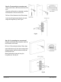
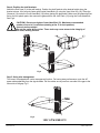
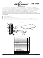
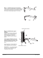
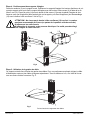
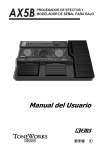
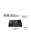
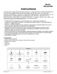
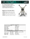
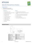
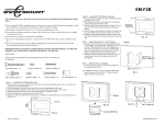
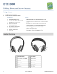
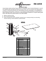
EM-AVSB
INSTRUCTIONS
PLEASE READ THESE INSTRUCTIONS CAREFULLY AND KEEP FOR FUTURE REFERENCE! IF YOU DO
NOT UNDERSTAND THE INSTRUCTIONS, OR DO NOT FEEL THAT YOU CAN FOLLOW THEM SAFELY,
CONTACT A QUALIFIED CONTRACTOR.THE WARRANTY WILL BE HONOURED IF ACCOMPANIED BY
AN ORIGINAL SALES RECEIPT, AND ONLY IF THE INSTRUCTIONS HAVE BEEN FOLLOWED EXACTLY.
Before beginning, please check to ensure you have all the parts listed below. To acquire missing parts
please visit www.everik.com/parts.html or call 1-866-604-6966.
Maximum shelf load 22 lbs
Do not install onto steel studs
Everik International will not be held liable for personal injury or damage resulting from mishandling,
incorrect mounting, incorrect assembly or product misuse
Parts List
1
2
3
4
5
6
7
8
9
10
11
12
13
14
15
www.everik.com
Description
Wall Bracket
Shelf Bracket
End Cap
Long Bolt
Wall Anchor
Socket Head Bolt
Set Screw
Plastic Pad
2.5mm Allen Key
3mm Allen Key
5mm Allen Key
Glass Shelf
Cross Head Bolt
Grommet
Joint Plank
Qty
1
1
2
2
2
2
4
4
1
1
1
1
1
1
1
________________________________________________
_AVSB.LO.092011.IM
Step 1: Install the plastic shelf pads
Attach Plastic Pads (8) to Shelf Bracket (2)
with Set Screws (7) using the 2.5mm Allen Key (9).
Do not over-tighten. See Fig 1.
Fig 1
Removable side cap
Step 2: Install shelf bracket
Remove one of the side caps from the
Wall Bracket (1), and slide the Joint
Plank (15) through the column.
Replace side cap once finished.
Attach the Shelf Bracket (2) to the Joint
Plank with the Socket Head Bolts (6)
using the 3mm Allen Key (10). Do not
over-tighten. See Fig 2.
Adjust the plate into the desired
position and then securely tighten all
bolts.
NOTE: The plate can be retracted to fit
all sizes of audio-video equipment.
www.everik.com
Fig 2
Removable side cap
________________________________________________
_AVSB.LO.092011.IM
Step 3a: For mounting to a wooden stud
Using a stud finder, mark the centre line of the
stud.
Using the wall bracket as a template, mark the
hole locations on the stud centre line.
Hole sideview
Drill two 4.5mm diameter holes, 50mm deep.
Level the wall bracket and attach to the wall
using the Long Bolts (4). See Fig 3a.
Fig 3a
Step 3b: For mounting to a concrete wall
Using the wall bracket as a template, mark the
hole locations on the wall.
Drill two 10.5mm diameter holes, 50mm deep.
Insert Wall Anchors (5) into the mounting holes.
Using a hammer, tap the anchors so they are
flush with the wall.
Hole sideview
Mount the bracket to the wall using the
Long Bolts (4). See Fig 3b.
Fig 3b
www.everik.com
________________________________________________
_AVSB.LO.092011.IM
Step 4: Position the shelf brackets
Attach the End Caps (3) to the wall bracket. Position the shelf bracket at the desired height along the
bracket column, then securely fasten with Socket Head Bolts (6) using the 3mm Allen Key (10). Place the
Grommet (14) under the Cross Head Bolt (13) before placing the glass shelf. Make sure the glass shelf lies
flat on the four plastic pads, then secure the glass shelf to the Joint Plank (15) using the Cross Head Bolt.
See Fig 4.
CAUTION!: Do not over-tighten Cross Head Bolt (13). Maximum recommended
number of turns is 5 revolutions (starting at the 12 o’clock position).
Use only tools provided.
Do not use power drill or driver. These tools may cause stress to the integrity of
the shelf, causing fracture.
Fig 4
Step 5: Using wire management
This mount is equipped with a wire management function. For best system performance, route the AC
power cable separately from the signal cables. Pull the cables one by one from one side of the gap to the
other side of the gap. Fig 5.
Fig 5
www.everik.com
________________________________________________
_AVSB.LO.092011.IM
EM-AVSB
INSTRUCTIONS
VEUILLEZ LIRE CES INSTRUCTIONS ATTENTIVEMENT ET LES GARDER POUR Y RÉFÉRER AU
BESOIN. SI VOUS NE COMPRENEZ PAS LES INSTRUCTIONS OU SI VOUS NE CROYEZ PAS ÊTRE EN
MESURE DE LES SUIVRE EN TOUTE SÉCURITÉ, VEUILLEZ COMMUNIQUER AVEC UN TECHNICIEN
QUALIFIÉ. LA GARANTIE NE SERA HONORÉE QU'EN LA PRÉSENCE DU COUPON DE CAISSE
ORIGINAL ET UNIQUEMENT SI LES INSTRUCTIONS ONT ÉTÉ SUIVIES À LA LETTRE.
Avant de commencer, assurez-vous d'avoir en votre possession toutes les pièces énumérées
ci-dessous. Pour obtenir des pièces manquantes, visitez www.everik.com/parts.html ou téléphonez au
1 866 604-6966.
Charge maximale 22 lb
Ne pas installer sur montant en métal
Everik International ne peut être tenue responsable de toute blessure ou dommage résultant d'une
mauvaise manipulation, d'une installation incorrecte, d'un assemblage inadéquat ou d'une mauvaise
utilisation
Liste des pièces
1
2
3
4
5
6
7
8
9
10
11
12
13
14
15
www.everik.com
Description
Support mural
Support d'étagère
Embout
Boulon long
Cheville
Boulon à tête creuse
Vis de fixation
Appui en plastique
Clé Allen 2,5 mm
Clé Allen 3 mm
Clé Allen 5 mm
Étagère en vitre
Boulon à tête cruciforme
Guide
Joint d'assemblage
Qté
1
1
2
2
2
2
4
4
1
1
1
1
1
1
1
________________________________________________
_AVSB.LO.092011.IM
Étape 1 : Installation des appuis en plastique
Fixez les appuis en plastique (8) au support d'étagère
(2) avec les vis de fixation (7) à l'aide de la clé Allen
2,5 mm (9). Ne serrez pas trop fort. Voir la Fig. 1.
Fig 1
Embout latéral amovible
Étape 2 : Installation du support
d'étagère
Retirez l'un des embouts latéraux du
support mural (1) et faites glisser le
joint d'assemblage (15) dans la
colonne. Replacez ensuite l'embout
latéral.
Fixez le support d'étagère (2) au joint
d'assemblage avec les boulons à tête
creuse (6) à l'aide de la clé Allen 3 mm
(10). Ne serrez pas trop fort. Voir la
Fig. 2.
Fig 2
Ajustez la plaque à l'endroit désiré et
vissez solidement tous les boulons.
Embout latéral amovible
REMARQUE : Il est possible d'ajuster
la plaque selon les dimensions de
l'équipement audio-vidéo.
www.everik.com
________________________________________________
_AVSB.LO.092011.IM
Étape 3a : Montage sur montant de bois
À l'aide d'un détecteur de montant, tracez la
ligne centrale du montant.
En vous servant du support mural comme
guide, marquez l'emplacement des trous sur
la ligne centrale du montant.
Vue latérale du trou
Percez deux trous de 4,5 mm de diamètre et
de 50 mm de profondeur.
Détecteur de montant
Montant de bois
Assurez-vous que le support mural est au
niveau et fixez-le au mur à l'aide des boulons
longs (4). Voir la Fig. 3a.
Fig 3a
Étape 3b : Montage sur mur de béton
En vous servant du support mural comme
guide, marquez l'emplacement des trous sur le
mur.
Percez deux trous de 10,5 mm de diamètre et
de 50 mm de profondeur.
Insérez les chevilles dans les trous de
montage. À l'aide d'un marteau, frappez sur les
chevilles jusqu'à ce qu'elles soient au ras du
mur.
Vue latérale du trou
Mur de béton
Fixez-le support au mur à l'aide des boulons
longs (4). Voir la Fig. 3b.
Fig 3b
www.everik.com
________________________________________________
_AVSB.LO.092011.IM
Étape 4 : Positionnement des supports d'étagère
Posez les embouts (3) sur le support mural. Positionnez le support d'étagère à la hauteur désirée sur la colonne du support mural, puis fixez le support d'étagère avec les boulons à tête creuse (6) à l'aide de la clé
Allen 3 mm (10). Placez le guide (14) sous le boulon à tête creuse (13) avant de placer l'étagère de vitre.
Assurez-vous que l'étagère est bien posée à plat sur les appuis, puis fixez l'étagère au joint d'assemblage
(15) avec le boulon à tête cruciforme. Voir la Fig. 4.
ATTENTION! : Ne vissez pas le boulon à tête cruciforme (13) trop fort. Le nombre
maximum recommandé est 5 tours (en partant de la position centrale verticale).
N'utilisez que les outils fournis.
N'utilisez pas de tournevis ou de perceuse électrique. Ces outils pourraient fragiliser l'étagère et causer des bris.
Fig 4
Étape 5 : Utilisation de la gestion du câble
Ce support est doté d'une fonction de gestion des câbles. Pour une performance optimale, dirigez le câble
d'alimentation secteur et les câbles de signaux séparément. Tirez les câbles un à un, d'un côté de l'ouverture vers l'autre côté de l'ouverture. Fig. 5.
Câbles
Fig 5
Points d'accès du rangement des câbles
www.everik.com
________________________________________________
_AVSB.LO.092011.IM