1
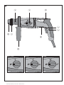
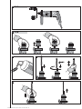
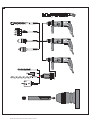
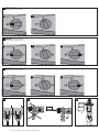
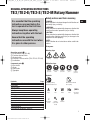
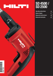
TE 2 / TE 2-S /
TE 2-M
Operating instructions
en
Brugsanvisning
da
Bruksanvisning
sv
Bruksanvisning
no
Käyttöohje
fi
Инструкция по зксплуатации
ru
Ръководство за обслужване
bg
Manual de utilizare
ro
Kullan›m k›lavuzu
tr
ar
Lietošanas pamācība
lv
Instrukcija
lt
Kasutusjuhend
et
Пайдалану бойынша басшылық
kk
ja
ko
zh
cn
Printed: 03.06.2014 | Doc-Nr: PUB / 5170565 / 000 / 01
1
1
2
4
1
TE2-M
2
3
5
6 7
9
8
TE 2 / TE 2-E
TE 2-S
TE2-M
1
2
Printed: 03.06.2014 | Doc-Nr: PUB / 5170565 / 000 / 01
2 TE2-M
1
TE2-M
2
3 TE2-M
4
5b
Printed: 03.06.2014 | Doc-Nr: PUB / 5170565 / 000 / 01
5a
6
TE 2
TE 2-S
1
TE 2-M
2
Printed: 03.06.2014 | Doc-Nr: PUB / 5170565 / 000 / 01
7 TE2 / TE2-E
7a
7b
7 TE2-S
7a
7c
7b
7 TE2-M
7a
7b
7d
1
1
1
2
8
2
2
9
10
1
TE2-M
2
1
2
Printed: 03.06.2014 | Doc-Nr: PUB / 5170565 / 000 / 01
01_BA_TE2_S_M_P8_en.qxd:02_BA_TE2_S_M_P1_en.qxd
1.10.2012
15:03 Uhr
Seite 1
ORIGINAL OPERATING INSTRUCTIONS
TE 2/TE 2-E/TE 2-S/TE 2-M Rotary Hammer
Safety notices and their meaning
It is essential that the operating
instructions are read before the
tool is operated for the first time.
Always keep these operating
instructions together with the tool.
Ensure that the operating
instructions are with the tool when
it is given to other persons.
-DANGERDraws attention to imminent danger that will lead to serious bodily injury or fatality.
-WARNINGDraws attention to a potentially dangerous situation that
could lead to serious personal injury or fatality.
-CAUTIONDraws attention to a potentially dangerous situation that
could lead to slight personal injury or damage to the
equipment or other property.
-NOTEDraws attention to an instruction or other useful information.
Pictograms
Warning signs
Operating controls 햲 Chuck release ring (TE 2-M)
햳 Function selector switch
햴 Control switch
햵 Forwards / reverse switch (TE 2 / TE 2-S / TE 2-M)
햶 Lockbutton
General
warning
Warning:
electricity
Warning: hot
surface
Obligation signs
Component parts 햷 Dust shield
햸 Chuck
햹 Side handle
햺 Type plate
Wear eye
protection
Wear a safety
helmet
Wear ear
protection
Wear safety
gloves
Wear
breathing
protection
Symbols
Contents
Safety notices and their meaning
Description
Technical data
Safety rules
Before use
Operation
Drilling
Forwards/reverse rotation
Insert tools and accessories
Care and maintenance
Disposal
Manufacturer's warranty – tools
Troubleshooting
Declaration of conformity (original)
Page
1
2
3
4
6
6
6
7
7
7
8
8
9
9
Read the operating
instructions before use.
Return waste material
for recycling.
A
V
W Hz
Amps
Volts
Watts
~
no
Alternating
current
Nominal
speed under
no load
∅
Hertz
/min
Revolutions
per minute
Diameter
1
Printed: 03.06.2014 | Doc-Nr: PUB / 5170565 / 000 / 01
en
01_BA_TE2_S_M_P8_en.qxd:02_BA_TE2_S_M_P1_en.qxd
en
The numbers refer to the illustrations. The illustrations
can be found on the fold-out cover pages. Keep these
pages open while you read the operating instructions.
In these operating instructions, the power tool to which
these operating instructions apply is referred to as “the
tool”.
Description
The TE 2 / TE 2-E / TE 2-S / TE 2-M is an electrically powered rotary hammer with pneumatic hammering mechanism designed for professional use.
The following items are supplied: power tool, (quickrelease chuck TE 2-M), operating instructions, grease
(except TE 2-E), toolbox, side handle, cleaning cloth,
Depth gauge.
The following conditions must always be observed
when the tool is in use:
– The tool must be connected to an alternating current
electric supply in compliance with the information
given on the type plate.
– The tool is for hand-held use only.
– The tool must not be used in places where the surrounding conditions may present a risk of explosion.
– Changes or modifications to the tool are not permissible.
– To avoid the risk of injury, use only the genuine Hilti
1.10.2012
15:03 Uhr
Seite 2
accessories and additional equipment specified for
use with this tool.
– Observe the information printed in the operating
instructions concerning operation, care and maintenance. The tool and its ancillary equipment may
present hazards when used incorrectly by untrained
personnel or when used not as directed.
– The tool is intended for professional use.The tool
may be operated, serviced and repaired only by
authorized, trained personnel. This personnel must
be informed of any special hazards that may be
encountered.
Main features of the tool
Class II electrical protection (double insulated) Z
Mechanical torque-limiting clutch
Grip and side handle with vibration absorption
TE-C chuck
TE-C insert tool system
Variable speed switch
Rotary-only drilling mode
Gearing and hammering mechanism with permanent
grease lubrication
Pivotable side handle (360°)
Mechanical depth gauge
Interface for quick-release chuck (TE 2-M)
Precision hammering action (TE 2-S)
High spindle speed without hammering action (TE 2-M)
Lockbutton for sustained operation
Right of technical changes reserved
The tool is designed for the following uses:
Use
TE 2 / TE 2-E / TE 2-S / TE 2-M:
Hammer drilling in concrete,
masonry and natural stone
TE 2-S:
Drilling with precision
hammering action in perforated
brick, tiles and marble
TE 2 / TE 2-E / TE 2-S:
Drilling in wood, drywall panels
and metal
Required insert tools
Diameter range
Drill bits with TE-C connection end Drilling in concrete:
– Short hammer drill bits
Anchor holes of 4–22 mm dia.
– Long hammer drill bits
Through holes of 4–22 mm dia.
Drill bits with TE-C connection end Drilling in brittle materials:
– TE-C hammer drill bits
Anchor holes of 4–22 mm dia.
– Thin-barrel core bits
Cutting sockets of 25–68 mm dia.
Quick-release chuck with TE-C adaptor for insert
tools with cylindrical shank or hexagonal shank
for rotary-only drilling
Wood drill bits
4–20 mm dia.
Metal drill bits
3–13 mm dia.
Hole saws
25–68 mm dia.
TE 2-M:
Drilling in wood, drywall panels, Interchangeable quick-release chuck for
tiles and metal
insert tools with cylindrical shank or hexagonal
shank for rotary-only drilling:
Wood drill bits
4–10 mm dia. in 2nd gear
10–20 mm dia. in 1st gear
Metal/stepped drill bits
3– 8 mm dia. in 2nd gear
8–13 mm dia. in 1st gear
Hole saws
25–68 mm dia. in 1nd gear
2
Printed: 03.06.2014 | Doc-Nr: PUB / 5170565 / 000 / 01
01_BA_TE2_S_M_P8_en.qxd:02_BA_TE2_S_M_P1_en.qxd
1.10.2012
15:03 Uhr
Seite 3
Technical data
Rated power
Nominal voltage *
Nominal current input *
Mains frequency
Weight of tool without side handle
Weight as per EPTA-Procedure 01/2003
Dimensions (l×h×w)
Minimum distance between wall and hole drilled
Speed
Hammering speed:
Precision hammering action
Full hammering action
Single impact energy Nm (J):
Precision hammering action
Full hammering action
Typical drilling performance in medium-hard B35
concrete
650 W
100 V 110 V 120 V 220 V 230 V 240 V
6.9 A 6.5 A 6.5 A 3.1 A 3.0 A 2.9 A
50–60 Hz
2.4 kg (TE2 / TE2-S / TE2-E)
2.7 kg (TE2-M)
2.7 kg (TE2 / TE2-S / TE2-E)
2.9 kg (TE2-M)
352×203×89 mm (TE 2 / TE 2-E / TE 2-S)
360×203×89 mm (TE 2-M)
34 mm
0– 930 /min. (hammer drilling)
0–1200 /min (in 1st gear TE2 / TE2-E / TE2-S / TE2-M)
0–2500 /min (in 2nd gear TE 2-M)
en
0–2600 /min (TE 2-S)
0–4600 /min (TE 2 / TE 2-E / TE 2-S / TE 2-M)
0.6 Nm (TE 2-S)
1.8 Nm (TE 2 / TE 2-E / TE 2-S / TE 2-M)
8 mm dia.: 550 mm/min
10 mm dia.: 500 mm/min
12 mm dia.: 400 mm/min
-NOTEThe vibration emission level given in this information sheet has been measured in accordance with a standardised
test given in EN 60745 and may be used to compare one tool with another. It may be used for a preliminary assessment of exposure. The declared vibration emission level represents the main applications of the tool. However if
the tool is used for different applications, with different accessories or poorly maintained, the vibration emission
may differ. This may significantly increase the exposure level over the total working period. An estimation of the
level of exposure to vibration should also take into account the times when the tool is switched off or when it is
running but not actually doing the job. This may significantly reduce the exposure level over the total working period. Identify additional safety measures to protect the operator from the effects of vibration such as: maintain the
tool and the accessories, keep the hands warm, organisation of work patterns.
Noise and vibration information (measured in accordance with EN 60745-2-6):
Typical A-weighted sound power level (LwA):
102 dB (A)
Typical A-weighted emission sound power level (LpA): 91dB (A)
For the given sound power level
as per EN 60745, the tolerance is
3 dB
Wear ear protection!
Triaxial vibration value (vibration vector sum)
measured in accordance with EN 60745-2-1
Drilling in metal, (ah, D)
2.8 m/s2
measured in accordance with EN 60745-2-6
Hammer drilling in concrete, (ah, HD)
13.5 m/s2
Uncertainty (K) for triaxial vibration value
1.5 m/s2
* The tool is offered in different versions for various mains voltages. Please refer to the information on the
type plate for the nominal voltage and nominal current input of your tool.
3
Printed: 03.06.2014 | Doc-Nr: PUB / 5170565 / 000 / 01
01_BA_TE2_S_M_P8_en.qxd:02_BA_TE2_S_M_P1_en.qxd
Safety rules
1. General power tool safety warnings
en
WARNING! Read all safety warnings and all
instructions. Failure to follow the warnings and instructions may result in electric shock, fire and/or serious
injury. Save all warnings and instructions for future
reference. The term “power tool” in the warnings refers
to your mains-operated (corded) power tool orbatteryoperated (cordless) power tool.
1.1 Work area safety
a) Keep work area clean and well lit. Cluttered or dark
areas invite accidents.
b) Do not operate power tools in explosive atmospheres, such as in the presence of flammable liquids, gases or dust. Power tools create sparks which
may ignite the dust or fumes.
c) Keep children and bystanders away while operating a power tool. Distractions can cause you to lose
control.
1.2 Electrical safety
a) Power tool plugs must match the outlet. Never modify the plug in any way. Do not use any adapter plugs
with earthed (grounded) power tools. Unmodified
plugs and matching outlets will reduce risk of electric shock.
b) Avoid body contact with earthed or grounded surfaces, such as pipes, radiators, ranges and refrigerators. There is an increased risk of electric shock
if your body is earthed or grounded.
c) Do not expose power tools to rain or wet conditions.
Water entering a power tool will increase the risk of
electric shock.
d) Do not abuse the cord. Never use the cord for carrying, pulling or unplugging the power tool. Keep
cord away from heat, oil, sharp edges or moving
parts. Damaged or entangled cords increase the risk
of electric shock.
e) When operating a power tool outdoors, use an extension cord suitable for outdoor use. Use of a cord suitable for outdoor use reduces the risk of electric shock.
f) If operating a power tool in a damp location is
unavoidable, use a residual current device (RCD)
protected supply. Use of an RCD reduces the risk of
electric shock.
1.3 Personal safety
a) Stay alert, watch what you are doing and use common sense when operating a power tool. Do not use
a power tool while you are tired or under the influence of drugs, alcohol or medication. A moment of
inattention while operating power tools may result in
serious personal injury.
b) Use personal protective equipment. Always wear
eye protection. Protective equipment such as dust
mask, non-skid safety shoes, hard hat, or hearing
protection used for appropriate conditions will reduce
personal injuries.
4
Printed: 03.06.2014 | Doc-Nr: PUB / 5170565 / 000 / 01
1.10.2012
15:03 Uhr
Seite 4
c) Prevent unintentional starting. Ensure the switch is
in the off-position before connecting to power source
and/or battery pack, picking up or carrying the tool.
Carrying power tools with your finger on the switch
or energising power tools that have the switch on
invites accidents.
d) Remove any adjusting key or wrench before turning the power tool on. A wrench or a key left attached
to a rotating part of the power tool may result in personal injury.
e) Do not overreach. Keep proper footing and balance
at all times. This enables better control of the power tool in unexpected situations.
f) Dress properly. Do not wear loose clothing or jewellery. Keep your hair, clothing and gloves away
from moving parts. Loose clothes, jewellery or long
hair can be caught in moving parts.
g) If devices are provided for the connection of dust
extraction and collection facilities, ensure these
are connected and properly used. Use of dust collection can reduce dust-related hazards.
1.4 Power tool use and care
a) Do not force the power tool. Use the correct power
tool for your application. The correct power tool will
do the job better and safer at the rate for which it was
designed.
b) Do not use the power tool if the switch does not turn
it on and off. Any power tool that cannot be controlled
with the switch is dangerous and must be repaired.
c) Disconnect the plug from the power source and/or
the battery pack from the power tool before making
any adjustments, changing accessories, or storing
power tools. Such preventive safety measures reduce
the risk of starting the power tool accidentally.
d) Store idle power tools out of the reach of children
and do not allow persons unfamiliar with the power tool or these instructions to operate the power
tool. Power tools are dangerous in the hands of
untrained users.
e) Maintain power tools. Check for misalignment or
binding of moving parts, breakage of parts and any
other condition that may affect the power tool’s operation. If damaged, have the power tool repaired
before use. Many accidents are caused by poorly
maintained power tools.
f) Keep cutting tools sharp and clean. Properly maintained cutting tools with sharp cutting edges are less
likely to bind and are easier to control.
g) Use the power tool, accessories and tool bits etc.
in accordance with these instructions, taking into
account the working conditions and the work to be
performed. Use of the power tool for operations different from those intended could result in a hazardous
situation.
1.5 Service
a) Have your power tool serviced by a qualified repair
person using only identical replacement parts. This
will ensure that the safety of the power tool is maintained.
01_BA_TE2_S_M_P8_en.qxd:02_BA_TE2_S_M_P1_en.qxd
2. Hammer safety warnings
a) Wear ear protectors. Exposure to noise can cause
hearing loss.
b) Use auxiliary handle(s), if supplied with the tool.
Loss of control can cause personal injury.
c) Hold power tool by insulated gripping surfaces,
when performing an operation where the cutting
accessory may contact hidden wiring ir its own cord.
Cutting accessory contacting a “live” wire may make
exposed metal parts of the power tool ”live” and could
give the operator an electric shock.
3. Additional safety rules
3.1 Personal safety
a) Always hold the tool with both hands on the grips
provided. Keep the grips dry, clean and free from
oil and grease.
b) Exercise your fingers during pauses between work
to improve the blood circulation in your fingers.
c) Avoid contact with rotating parts. Switch the tool on
only once it has been brought into the working position close to the workpiece.
d) Breathing protection must be worn when the tool is
used without a dust removal system for work that
creates dust.
e) To avoid tripping and falling when working, always
lead the sypply cord, extension cord and dust extraction hose away to the rear.
f) When drilling or chiseling through-holes, check that
no person is present in the danger area immediately behind the work surface.
g) Hold tool by insulated gripping surfaces when performing an operation where the cutting tool may
contact hidden wiring or its own cord. Contact with
a “live” wire will make exposed metal parts of the tool
“live” and shock the operator.
h) Children must be instructed not to play with the tool.
i) The tool is not intended for use by children, by debilitated persons or those who have received no instruction or training.
j) Dust from material such as paint containing lead, some
wood species, minerals and metal may be harmful.
Contact with or inhalation of the dust may cause allergic reactions and/or respiratory diseases to the operator or bystanders. Certain kinds of dust are classified as carcinogenic such as oak and beech dust especially in conjunction with additives for wood conditioning (chromate, wood preservative). Material containing asbestos must only be treated by specialists.
Where the use of a dust extraction device is possible it shall be used. To achieve a high level of dust
collection, use a suitable vacuum cleaner of the type
recommended by Hilti for wood dust and/or mineral dust together with this tool. Ensure that the workplace is well ventilated. The use of a dust mask of
filter class P2 is recommended. Follow national
requirements for the materials you want to work with.
3.2 Power tool use and care
a) Secure the workpiece. Use clamps or a vice to hold
1.10.2012
15:04 Uhr
Seite 5
the workpiece in place. The workpiece is thus held
more securely than by hand and both hands remain
free to operate the tool.
b) Ensure that the insert tools used are equipped with
the appropriate connection end system and that
they are properly fitted and secured in the chuck.
c) In the event of a power faillure, switch the tool off
and unplug the supply cord. This prevents inadvertent starting when the power returns.
d) In the event of an interruption in the electric supply
and before laying the tool down each time, check
that the lockbutton for sustained operation has been
released. Release the lockbutton if necessary. Failure to observe this point could cause the tool to start
unexpectedly when the power returns.
e) Do not apply an excessive quantity of grease to the
drill bit connection end. Excess grease may otherwise be forced out of the chuck during operation.
3.3 Electrical safety
a) Before beginning work, check the working area (e.g.
with a metal detector) to ensure that no concealed
electric cables or gas and water pipes are present.
External metal parts of the tool may become live if,
for example, an electric cable is damaged inadvertenly.
This presents a serious risk of electric shock.
b) Check the condition of the supply cord and its plug
connections and have it replaced by a qualified electrician if damage is found. Check the condition of
the extension cord and replace it if damage is found.
Do not touch the supply in the event of it suffering
damage while working. Disconnect the supply cord
plug from the socket. Damaged supply cords and
extension cords present a risk of electric shock.
c) Dirty or dusty electric tools should thus be checked
at a Hilti service center at regular intervals, especially if used frequently for working on conductive
materials. Dust (especially dust from conductive
materials) or dampness adhering to the surface of
the tool may, under unfavorable conditions, present
a risk of electric shock.
3.4 Work area
a) Ensure that the workplace is well lit.
b) Ensure that the workplace is well ventilated.
Poorly ventilated workplaces may be injurious to the
health due to exposeure to dust.
3.5 Personal protective equipment
The user and any other persons in the vicinity must
wear suitable eye protection, a hard hat, ear protection
and protective gloves when the tool is in use. Breathing protection must be worn if no dust removal system is used.
Wear eye
protection
Wear a
hard hat
Wear ear
protection
Wear
protective
gloves
Wear
breathing
protection
5
Printed: 03.06.2014 | Doc-Nr: PUB / 5170565 / 000 / 01
en
01_BA_TE2_S_M_P8_en.qxd:02_BA_TE2_S_M_P1_en.qxd
Before use
is essential that the safety precautions printed in these
en Itoperating
instructions are read and observed.
Fitting the side handle
1.Unplug the tool from the mains socket.
2. Release the side handle clamping band by turning
the handle in a counter-clockwise direction.
3. Fit the side handle clamping band over the chuck
and onto the cylindrical section at the front end of
the tool.
4. Pivot the side handle into the desired position.
5. Tighten the side handle securely to prevent inadvertent movement.
1.10.2012
15:04 Uhr
Seite 6
so that the clutch releases in the event of the drill bit
sticking.
Use a vice or clamp to secure loose workpieces.
Fitting the insert tool 5a
1. Unplug the supply cord from the mains socket.
2. Check that the connection end of the insert tool is
clean and lightly greased. Clean it and grease it if necessary.
3. Check that the sealing lip of the dust shield is clean
and in good condition. Clean the dust shield if necessary or replace it if the sealing lip is damaged.
4. Push the connection end of the insert tool into the
chuck and, while applying slight pressure, rotate the
insert tool until it engages in the guide grooves.
5. Push the insert tool further into the chuck until it is
heard to engage.
6. Check that the insert tool has engaged correctly (pull
by hand).
Removing the insert tool
5b
Check that the side handle is seated securely.
The supply voltage must correspond to the information
on the type plate.
-CAUTION– The insert tool may become hot during use. There is
a risk of burning the hands. Wear protective gloves
when changing insert tools.
1. Unplug the supply cord from the mains socket.
2. Open the chuck by pulling back the locking sleeve.
3. Pull the insert tool out of the chuck.
If extension cords are used: Only extension cords of a
type approved for the intended use and of adequate cross
section may be used. Failure to observe this point may
result in reduced performance of the tool and overheating
of the cord. Damaged extension cords must be replaced.
Use only insert tools with TE-C connection end.
Don’t exert excessive pressure on the tool. This will not
increase its hammering power.
At low temperatures: The tool requires to reach a minimum operating temperature before the hammering mechanism begins to operate. Switch on the tool and position
the tip of the drill bit on the work surface. While the tool
is running, apply light pressure briefly and repeatedly
until the hammering mechanism begins to operate.
Operation
CAUTION: In the event of the drill bit sticking, the tool
will pivot about its own axis.
Always use the tool with the side handle fitted and hold
it securely with both hands applying an opposing torque
6
Printed: 03.06.2014 | Doc-Nr: PUB / 5170565 / 000 / 01
Drilling
Hammer drilling (TE 2 / TE 2-E / TE 2-S / TE 2-M) /
precision hammering action (TE 2-S)
1. Insert the drill bit into the chuck.
2. Turn the function selection switch to the hammer
drilling position ( ) until the gearing is engaged
7a .
Rotate the chuck spindle slightly if necessary. Check
that forwards rotation is selected (I.).
3. Use of the precision hammering action ( ) is advantageous when drilling in brittle materials (e.g. tiles,
marble, perforated brick). This will improve the quality of the holes drilled 7c .
4. Connect the supply cord to the power supply.
5. Pivot the side handle, with or without the depth gauge,
to the desired angle and tighten the handle to lock it
in this position. Check that the side handle is seated
and attached securely .
6. Bring the tip of the drill bit into contact with the work
surface at the position where the hole is to be drilled
and press the control switch slowly. Drill at low speed
until the drill bit centres itself in the hole.
7. Press the control switch fully and continue drilling at
full power.
01_BA_TE2_S_M_P8_en.qxd:02_BA_TE2_S_M_P1_en.qxd
Rotary-only drilling (without hammering action)
(TE 2 / TE 2-E / TE 2-S)
Turn the function selection switch to the drilling position ( ) 7b . When the switch is in this position, only the
rotary movement is transmitted to the TE-C insert tool
or chuck adaptor for insert tools with cylindrical shanks.
Rotary-only drilling (without hammering action)
(TE 2-M)
Turn the function selection switch to the 1st gear or 2nd
gear drilling position 7b 7d . When the switch is in these
positions, only the rotary movement is transmitted to
the TE-C insert tool or quick-release chuck.
Use of a high spindle speed can be advantageous when
drilling in metal or wood. For higher drilling speed, the
function selection switch must be engaged in the 2nd
gear position ( 2) 7d .
Changing the chuck (TE 2-M)
Pull the chuck release ring towards the front and remove
the chuck completely. When fitting the chuck, pull the
release ring towards the front and hold it in this position. Push the chuck onto the guide tube as far as it will
go and release the ring. Rotage the chuck until it engages
and the ring snaps back into its original position . The
TE-C interchangeable chuck or quick-release interchangeable chuck may be fitted to the TE 2-M with chuck
interface .
Drilling using the depth gauge
We recommend the use of the depth gauge for drilling
holes accurately to the desired depth. The depth gauge
is integrated in the side handle, which can be pivoted
and locked in position. Release the side handle (turn
counter-clockwise), set the depth gauge to the desired
drilling depth and tighten the side handle (turn clockwise) .
Forwards / reverse rotation
(TE 2 / TE 2-S / TE 2-M)
For screwdriving, the desired direction of rotation can
be selected simply by moving the switch .
For forwards rotation, select position ( ) and for reverse rotation, select position ( ).
When the tool is operated in reverse rotation, the function selection switch should be engaged in the position for drilling without hammering action ( / 1st gear).
For drilling, always ensure that forwards rotation
( ) is selected.
Insert tools and accessories
Use only insert tools with TE-C connection end or straight
shank bits with quick release chuck or adaptor .
1.10.2012
15:04 Uhr
Seite 7
Hilti power tools have been designed to work optimally as a system together with Hilti insert tools.
Accordingly, highest performance and longest life
expectancy can be achieved when you use this power tool with Hilti insert tools. A comprehensive programme of insert tools and accessories is available for
the TE-C system . Details of the entire programme
can be found in the current Hilti product catalogue.
Should you require insert tools not included in the standard programme, please contact the Hilti customer service department or your Hilti sales representative. Hilti
offers a comprehensive range of special insert tools in
professional quality.
Check your insert tools at regular intervals and replace
them in good time. A damaged or badly worn connection end may result in damage to the power tool. Drill
bits with chipped or broken carbide tips may no longer
drill holes of the specified diameter, thus influencing
their suitability for anchor fastenings.
Please observe the instructions on care and maintenance of your insert tools given in the following section.
Dust removal (TE DRS-S) A DRS extraction head can be attached to the side handle / depth gauge. An industrial vacuum cleaner is used
to remove drilling dust and fragments.
Care and maintenance
-CAUTIONDisconnect the supply cord plug from the power outlet.
Care of insert tools
Clean off dirt and dust deposits adhering to the insert
tools and protect them from corrosion by wiping the
insert tools from time to time with an oil-soaked rag.
Care of the power tool
-CAUTIONKeep the power tool, especially its grip surfaces, clean
and free from oil and grease. Do not use cleaning
agents which contain silicone.
The outer casing of the power tool is made froM impactresistant plastic. Sections of the grip are made from a
synthetic rubber material.
Never operate the power tool when the ventilation slots
are blocked. Clean the ventilation slots carefully using
a dry brush. Do not permit foreign objects to enter the
interior of the power tool. Clean the outside of the pow7
Printed: 03.06.2014 | Doc-Nr: PUB / 5170565 / 000 / 01
en
01_BA_TE2_S_M_P8_en.qxd:02_BA_TE2_S_M_P1_en.qxd
er tool at regular intervals with a slightly damp cloth. Do
not use a spray, steam pressure cleaning equipment or
running water for cleaning. This may negatively affect
the electrical safety of the power tool.
en Cleaning or replacing the dust shield
Clean the dust shield on the chuck with a dry, clean cloth
at regular intervals. Clean the sealing lip by wiping it
carefully and then grease it again lightly with Hilti grease.
It is essential that the dust shield is replaced if the sealing lip is found to be damaged. Push the tip of a screwdriver under the edge of the dust shield and prise it out
toward the front. Clean the area of the chuck in contact
with dust shield and then fit a new dust shield. Press it
in firmly until it engages.
1.10.2012
15:04 Uhr
Seite 8
Maintenance
-WARNINGRepairs to the electrical section of the power tool may
be carried out only by trained electrical specialists.
Check all external parts of the power tool for damage at
regular intervals and check that all controls operate faultlessly. Do not operate the power tool if parts are damaged or when the controls do not function faultlessly. If
necessary, the power tool should be repaired by Hilti
Service.
Checking the power tool after care and maintenance
After carrying out care and maintenance work on the
power tool, check that all protective and safety devices
are fitted and that they function faultlessly.
Disposal
Return waste material for recycling
Most of the materials from which Hilti power tools are manufactured can be recycled. The materials must be correctly separated before they can be recycled. In many countries, Hilti has already made arrangements for taking
back your old electric tools for recycling. Please ask your Hilti customer service department or Hilti sales representative for further information.
Only for EU countries
Disposal of electric tools together with household waste is not permissible!
In observance of European Directive on waste electrical and electronic equipment and its implementation in accordance with national law, electric tools that have reached the end of their life must be
collected separately and returned to an environmentally compatible recycling facility.
Manufacturer's warranty – tools
Hilti warrants that the tool supplied is free of defects
in material and workmanship. This warranty is valid so
long as the tool is operated and handled correctly,
cleaned and serviced properly and in accordance with
the Hilti Operating Instructions, and the technical system is maintained. This means that only original Hilti
consumables, components and spare parts may be
used in the tool.
This warranty provides the free-of-charge repair or
replacement of defective parts only over the entire lifespan of the tool. Parts requiring repair or replacement
as a result of normal wear and tear are not covered by
this warranty.
Additional claims are excluded, unless stringent
national rules prohibit such exclusion. In particular,
8
Printed: 03.06.2014 | Doc-Nr: PUB / 5170565 / 000 / 01
Hilti is not obligated for direct, indirect, incidental
or consequential damages, losses or expenses in
connection with, or by reason of, the use of, or inability to use the tool for any purpose. Implied warranties
of merchantability or fitness for a particular purpose
are specifically excluded.
For repair or replacement, send tool or related parts
immediately upon discovery of the defect to the address
of the local Hilti marketing organization provided.
This constitutes Hilti's entire obligation with regard to
warranty and supersedes all prior or contemporaneous comments and oral or written agreements concerning warranties.
01_BA_TE2_S_M_P8_en.qxd:02_BA_TE2_S_M_P1_en.qxd
1.10.2012
15:04 Uhr
Seite 9
Troubleshooting
Symptom
The tool doesn’t start
Possible cause
Fault in the electric power supply
Defective supply cord or plug
Switch defective
No hammering action
The tool is too cold
Tool doesn’t produce full
power
Drill bit cannot be released
Function selection switch
set to rotary drilling
Cross-section of the
extension cord is inadequate
Control switch is not pressed fully
Function selection switch set
to precision hammering action
Forwards / reverse switch set
to reserve when drilling
Chuck not opened fully
EC declaration of conformity (original)
Description:
Designation:
Year of design:
Rotary Hammer
TE2 / TE 2-E / TE2-S / TE2-M
2005
Possible solution
Plug in another electric tool and check
whether it starts
Have it checked by an electrical
specialist and replace if necessary
Have it checked by an electrical
specialist and replace if necessary
Allow tool to reach the minimum
operating temperature
See section “Before use”
Set function selection switch to
hammer drilling
Use an extension cord of adequate crosssectional area. See section “Before use”
Press the control switch as far as it will go
Set function selection switch
to hammer drilling
Set forwards / reverse switch
to forwards
Pull the chuck locking sleeve back as
far as it will go and remove the insert
tool
Technical documentation filed at:
Hilti Entwicklungsgesellschaft mbH
Zulassung Elektrowerkzeuge
Hiltistrasse 6
86916 Kaufering
Deutschland
We declare, under our sole responsibility, that this product
complies with the following directives and standards:
2004/108/EC, 2006/42/EC, EN 60745-1, EN 60745-2-6,
EN 12100, 2011/65/EU
Hilti Corporation, Feldkircherstrasse 100,
FL-9494 Schaan
Paolo Luccini
Head of BA
Quality and Process Management
Business Area
Electric Tools & Accessories
01/2012
Jan Doongaji
Senior Vice President
BU Drilling & Demolition
01/2012
9
Printed: 03.06.2014 | Doc-Nr: PUB / 5170565 / 000 / 01
en
01_BA_TE2_S_M_P8_en.qxd:02_BA_TE2_S_M_P1_en.qxd
10
Printed: 03.06.2014 | Doc-Nr: PUB / 5170565 / 000 / 01
1.10.2012
15:04 Uhr
Seite 10
Hilti Corporation
Printed: 03.06.2014 | Doc-Nr: PUB / 5170565 / 000 / 01
2059548 / A3
2059548
Hilti = registered trademark of Hilti Corp., Schaan
W 2740 | 0514 | 10-Pos. 8 | 1
Printed in China © 2014
Right of technical and programme changes reserved S. E. & O.
*2059548*
LI-9494 Schaan
Tel.: +423 / 234 21 11
Fax: +423 / 234 29 65
www.hilti.com