1
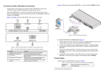
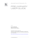
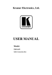
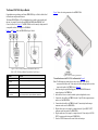
The Kramer WSI-1VGA Step-in Module
Congratulations on purchasing your Kramer WSI-1VGA Step-in Module which is ideal
for boardrooms and presentation rooms.
The Kramer WSI-1VGA is a VGA and unbalanced stereo audio, remote control panel
that can, for example, fit into the Kramer TBUS-1A, TBUS-4i or TBUS-5i Table
Connection Boxes (see Figure 3). The WSI-1VGA is used for remotely taking control of
a compatible switcher, for example, the VP-81KSi.
Figure 1 and Table 1 define the WSI-1VGA Step-in Module.
Figure 2 shows the wiring connections for the WSI-1VGA.
Figure 1: WSI-1VGA Step-in Module Front and Rear Panel View
Table 1: WSI-1VGA Step-in Module Front and Rear Panel Features
#
Feature
Function
1
STEP-IN Button
Press to select the switcher input to which the WSI-1VGA is connected
2
PC INPUT VGA 15-pin HD (F) Connect to the video source (up to UXGA)
Connector
3
AUDIO INPUT 3.5mm Mini
Jack
Connect to the unbalanced stereo audio source
4
Audio Output 3.5mm Mini
Jack
Connect to the unbalanced stereo audio input of the switcher
5
Video Output VGA 15-pin HD Connect to the video input of the switcher. (The cable used must connect
(F) Connector
all pins, for example, Kramer cable CP-GM/GM or C-GMA/GMA)
Figure 2: WSI-1VGA Wiring Connections
To install and connect the WSI-1VGA as illustrated in Figure 2:
Note: The following steps assume that you have video (with 15-pin HD (M)
connectors) and audio (with 3.5mm mini jacks) cables running from the switcher
inputs to the inside of the TBUS-1A (see Figure 3).
1. After removing the required blanking panel, insert the WSI-1VGA into the
required opening of the TBUS-1A.
2. Insert the four screws to secure the module in place and tighten the screws.
3. Connect the video cable in the TBUS-1A to the 15-pin HD video output connector
on the rear of the WSI-1VGA.
4. Connect the audio cable in the TBUS-1A to the 3.5mm mini jack audio output
connector on the rear of the WSI-1VGA.
5. Plug the video source (for example, a computer) into the 15-pin HD PC INPUT
connector on the front panel of the WSI-1VGA.
6. Plug the audio source (for example, a computer) into the 3.5mm mini jack AUDIO
INPUT connector on the front panel of WSI-1VGA.
7. Press the STEP IN button to take control of the switcher input.
Figure 3 illustrates the WSI-1VGA mounted in the TBUS-1A.
Figure 3: WSI-1VGA Mounted in the TBUS-1A
WSI-1VGA
Step-in Module
Installation Instructions
Product Details
Product details of the WSI-1VGA are shown in Table 2.
Table 2: Technical Specifications1 of the WSI-1VGA
DIMENSIONS:
WEIGHT:
ACCESSORIES:
For the latest information on our products and a list of Kramer distributors,
visit our Web site at www.kramerelectronics.com
U
U
Dual insert size—8cm x 8cm x 4.1cm (3.2" x 3.2" x 1.6”) W, D, H
0.2kg (0.44lbs) approx.
M3 x 6mm screws (2) black
Kramer Electronics, Ltd.
Web site: www.kramerelectronics.com
E-mail: [email protected]
P/N: 2900-000756 REV 1
PN:
1 Product details are subject to change without notice
2900- 000756
Rev:
1