1
# 21 4268
Panda Sport
D
GB
F
I
ES
Bauanleitung
Building instructions
Notice de construction
Instruzioni di montaggio
Instrucciones de montaje
Abbildungen
Illustrations
Illustrations
Illnstrazioni
Iiustraciónes
... 28 - 32
2 ... 11
12 ... 21
22 ... 37
38 ... 47
48 ... 57
Ersatzteile
Replacement parts
Pièces de rechanges
Parti di ricambio
Repuestos
58 - 59
Erhältliche Varianten / Available versions / Version D disponible / Varianti disponibili / Variantes disponibles
# 21 4268
Panda Sport
# 26 4268
Panda Sport
# 26 4272
Panda Sport
© Copyright by MULTIPLEX 2013
# 26 4269
Panda
# 1 3268
Panda
# 1 3269
Panda
Version 1.0
Sicherheitshinweise für MULTIPLEX-Flugmodelle
Das Modell ist KEIN SPIELZEUG im üblichen Sinne.
D
Mit Inbetriebnahme des Modells erklärt der Betreiber, dass er den Inhalt der Betriebsanleitung, besonders zu Sicherheitshinweisen, Wartungsarbeiten, Betriebsbeschränkungen und Mängel kennt und inhaltlich nachvollziehen kann.
Dieses Modell darf nicht von Kindern unter 14 Jahren betrieben werden. Betreiben Minderjährige das Modell unter der
sachkundigen Erwachsenen, ist dieser für die Umsetzung
der Hinweise der BETRIEBSANLEITUNG verantwortlich.
DAS MODELL UND DAZUGEHÖRIGES ZUBEHÖR MUSS VON KINDERN UNTER 3 JAHREN FERNGEHALTEN
WERDEN! ABNEHMBARE KLEINTEILE DES MODELLS KÖNNEN VON KINDERN UNTER 3 JAHREN VERSCHLUCKT
WERDEN. ERSTICKUNGSGEFAHR!
Beim Betrieb des Modells müssen alle Warnhinweise der BETRIEBSANLEITUNG beachtet werden. Die Multiplex Mo
"
#
$%
&
"
'
"
Betriebes oder Missbrauches dieses Produktes, einschließlich der dazu benötigten Zubehörteile entstehen. Dies beinhaltet
direkte, indirekte, beabsichtigte und unabsichtliche Verluste und Beschädigungen und jede Form von Folgeschäden.
Jeder Sicherheitshinweis dieser Anleitung muss unbedingt befolgt werden und trägt unmittelbar zum sicheren Betrieb
Ihres Modells bei. Benutzen Sie Ihr Modell mit Verstand und Vorsicht, und es wird Ihnen und Ihren Zuschauern viel
Spaß bereiten, ohne eine Gefahr darzustellen. Wenn Sie Ihr Modell nicht verantwortungsbewusst betreiben, kann dies
zu erheblichen Sachbeschädigungen und schwerwiegenden Verletzungen führen. Sie alleine sind dafür verantwortlich,
dass die Betriebsanleitungen befolgt und die Sicherheitshinweise in die Tat umgesetzt werden.
Bestimmungsgemäße Verwendung
Das Modell darf ausschließlich im Hobbybereich verwendet werden. Jede weitere Verwendung darüber hinaus ist nicht
erlaubt. Für Schäden oder Verletzungen an Menschen und Tieren aller Art haftet ausschließlich der Betreiber des Modells
und nicht der Hersteller.
Zum Betrieb des Modells darf nur das von uns empfohlene Zubehör verwendet werden. Die empfohlenen Komponenten
sind erprobt und auf eine sichere Funktion passend zum Modell abgestimmt. Werden andere Komponenten verwendet
oder das Modell verändert, erlöschen alle Ansprüche an den Hersteller bzw. den Vertreiber.
Um das Risiko beim Betrieb des Modells möglichst gering zu halten, beachten Sie folgende Punkte:
zDas Modell wird über eine Funkfernsteuerung gelenkt. Keine Funkfernsteuerung ist sicher vor Funkstörungen.
Solche Störungen können dazu führen, dass Sie zeitweise die Kontrolle über Ihr Modell verlieren. Deshalb müssen Sie beim Betrieb Ihres Modells zur Vermeidung von Kollisionen immer auf große Sicherheitsräume in allen
Richtungen achten. Schon beim kleinsten Anzeichen von Funkstörungen müssen Sie den Betrieb Ihres Modells
einstellen!
zSie dürfen Ihr Modell erst in Betrieb nehmen, nachdem Sie einen kompletten Funktionstest und einen Reichweitentest, gemäß der Anleitung Ihrer Fernsteuerung, erfolgreich ausgeführt haben.
z ("
)
"
*%
+
'
/
nicht geblendet zu werden, oder bei anderen schwierigen Lichtverhältnissen.
z5
)
"
6
5
*
"
/"
)6"
ben werden, die das Wahrnehmungs- und Reaktionsvermögen beeinträchtigen.
zFliegen Sie nur bei Wind- und Wetterverhältnissen, bei denen Sie das Modell sicher beherrschen können. Be6
"
+"
7
"
7
"
8&6
"
"
)
5
nehmen können.
zFliegen Sie nie an Orten, an denen Sie andere oder sich selbst gefährden können, wie z.B. Wohngebiete, Überlandleitungen, Straßen und Bahngleise.
z9"
"
;
<
=
>
6
?
wirkliches Können, sondern setzt andere Leute nur ein unnötiges Risiko aus. Weisen Sie auch andere Piloten
in unser aller Interesse auf diese Tatsache hin. Fliegen Sie immer so, dass weder Sie noch andere in Gefahr
kommen. Denken Sie immer daran, dass auch die allerbeste Fernsteuerung jederzeit gestört werden kann. Auch
langjährige, unfallfreie Flugpraxis ist keine Garantie für die nächste Flugminute.
2
D
Restrisiken
Auch wenn das Modell vorschriftsmäßig und unter Beachtung aller Sicherheitsaspekten betrieben wird, besteht immer
ein gewisses Restrisiko.
Eine ist daher obligatorisch. Falls Sie in einen Verein oder Verband eintreten, können Sie diese
#
"@
"
"
#
Q)
Y
"
Sie Modelle und Fernsteuerung immer absolut in Ordnung.
Folgende Gefahren können im Zusammenhang mit der Bauweise und Ausführung des Modells auftreten:
zVerletzungen durch die Luftschraube: Sobald der Akku angeschlossen ist, ist der Bereich um die Luftschraube
freizuhalten. Beachten Sie auch, dass Gegenstände vor der Luftschraube angesaugt werden können oder Gegenstände dahinter weggeblasen werden können. Das Modell kann sich in Bewegung setzen. Richten Sie es
daher immer so aus, dass es sich im Falle eines ungewollten Anlaufen des Motors nicht in Richtung anderer
Personen bewegen kann. Bei Einstellarbeiten, bei denen der Motor läuft oder anlaufen kann, muss das Modell
stets von einem Helfer sicher festgehalten werden.
z
[
"
;
"
"
\
]
"
)% und eine entsprechende Versicherung sind unabdingbar.
zAbsturz durch technisches Versagen oder unentdeckten Transport- oder Vorschaden. Die sorgfältige Überprüfung
des Modells vor jedem Flug ist ein Muss. Es muss jedoch immer damit gerechnet werden, dass es zu Material*"
6
6"
9"
"
8
"
"
"
6"
zBetriebsgrenzen einhalten. Übermäßig hartes Fliegen schwächt die Struktur und kann entweder zu plötzlichem
Materialversagen führen, oder bei späteren Flügen das Modell aufgrund von „schleichenden“ Folgeschäden
abstürzen lassen.
zFeuergefahr durch Fehlfunktion der Elektronik. Akkus sicher aufbewahren, Sicherheitshinweise der Elektronikkomponenten im Modell, des Akkus und des Ladegerätes beachten, Elektronik vor Wasser schützen. Auf ausreichende Kühlung bei Regler und Akku achten.
Die Anleitungen unserer Produkte dürfen nicht ohne ausdrückliche Erlaubnis der Multiplex Modellsport GmbH
& Co. KG (in schriftlicher Form) - auch nicht auszugsweise in Print- oder elektronischen Medien reproduziert
und / oder veröffentlicht werden.
3
D
Baukasten Panda Sport
# 21 4268
Machen Sie sich mit dem Bausatz vertraut!
MULTIPLEX - Modellbaukästen unterliegen während der Produktion einer ständigen Materialkontrolle. Wir hoffen, dass
$"6""
7
&
"
<
Q"
6Y
vor Verwendung zu prüfen,
da bearbeitete Teile vom Umtausch ausgeschlossen sind. Sollte ein Bauteil einmal nicht in Ordnung sein, sind wir nach
Überprüfung gern zur Nachbesserung oder zum Umtausch bereit. Senden Sie das Teil, bitte ausreichend frankiert, an
*
*%
"
/6""
Q'"Y
7
"beiten ständig an der technischen Weiterentwicklung unserer Modelle. Änderungen des Baukasteninhalts in Form, Maß,
Technik, Material und Ausstattung behalten wir uns jederzeit und ohne Ankündigung vor. Bitte haben Sie Verständnis
dafür, dass aus Angaben und Abbildungen dieser Anleitung keine Ansprüche abgeleitet werden können.
Achtung!
Ferngesteuerte Modelle, insbesondere Flugmodelle, sind kein Spielzeug im üblichen Sinne. Ihr Bau und Betrieb
erfordert technisches Verständnis, ein Mindestmaß an handwerklicher Sorgfalt sowie Disziplin und Sicherheitsbewusstsein.
Fehler und Nachlässigkeiten beim Bau und Betrieb können Personen- und Sachschäden zur Folge haben. Da der
6
5@
"
%@
?""
7"
$
"
+
+
"6
"
diese Gefahren hin.
Wichtiger Hinweis
("
)
"
+
&
'
"
^
)">*
\*"
6>
Verlust des Modells führen. Beachten Sie: In solchen Fällen gibt es von uns keinen Ersatz. Tasten Sie sich also vorsichtig
an die Grenzen heran. Das Modell ist auf den von uns empfohlenen Antrieb ausgelegt, kann aber nur einwandfrei gebaut
und unbeschädigt den Belastungen standhalten. Weitere Tuningmaßnahmen setzen Sachverstand und entsprechend
sinnvolle Maßnahmen zur weiteren Verstärkung voraus.
Fernsteuerelemente im Modell / sonstiges Zubehör
Empfohlene Ausrüstung:
MULTIPLEX Empfänger ab RX-5 light M-LINK
Best. Nr. 5 5808
oder
Empfänger RX-5 M-LINK telemetriefähig
Best. Nr. 5 5817
Damit können Sie auch die Telemetrie-Module verwenden und Ihr Modell beispielsweise
#"`q>`
`
Q6
<"6Y
""^
Servos
{|
*
9"`
oder
{|
*
9"
;
)
Q>
}
Y
Q>
}
Y
~
)"
$
9 6 5120
$
9 6 5119
Antriebssatz mit passendem Antriebsakku:
Antriebsatz „Panda Sport“ Li-BATT powered
Best. Nr. 33 3662
mit Brushless-Motor PERMAX BL-O 2812-1100,
Regler MULTIcont BL-20 SD, "66
=`$<<
'
q`
Q)Y
~
)
"`="
|
$"6"
^
Antriebssatz:
Antriebsatz „Panda Sport“
Best. Nr. 33 2662
mit Brushless-Motor PERMAX BL-O 2812-1100,
Regler MULTIcont BL-20 SD,
~
)
"`="
|
$"6"
^
Akkuempfehlung:
"66
=`$<<
'
q`
Q)Y
~
;""
^
Klebstoff:
Zacki ELAPOR ® 20g
Zacki ELAPOR ® Super liquid 10g
$
9
15 7321
Best.-Nr. 59 2727
Best.-Nr. 59 2728
Ladegerät:
Best.-Nr. 9 2545
Combo MULTIcharger LN-3008 EQU mit Netzgerät AC/DC 230V/12V 5,0A
Werkzeuge: Klingenmesser, div. Schlitz- und Kreuzschlitz-Schraubendreher, Steck- oder Gabelschlüssel SW10
Model Service Box ~
Q*
/""
Y
4
$`9
8 5500
Wichtiger Hinweis
Dieses Modell ist nicht aus Styropor ™! Daher sind Verklebungen mit Weißleim, Polyurethan oder Epoxy nicht möglich.
(
"
%
"
5"
"
"
#+
"""`q66
#6%
*+
?"6
`5=;8/
{{
5=;8/
;"6"
angepasste Sekundenkleber. Bei Verwendung von Zacki-ELAPOR® können Sie auf Kicker oder Aktivator weitgehend
verzichten. Wenn Sie jedoch andere Kleber verwenden, und auf Kicker/Aktivator nicht verzichten können, sprühen Sie
aus gesundheitlichen Gründen nur im Freien. Vorsicht beim Arbeiten mit allen Cyanacrylatklebern. Diese Kleber härten
u.U. in Sekunden, daher nicht mit den Fingern und anderen Körperteilen in Verbindung bringen. Zum Schutz der Augen
unbedingt Schutzbrille tragen! Von Kindern fernhalten! An einigen Stellen ist es auch möglich Heißkleber zu verwenden.
Wir weisen in der Anleitung ggf. darauf hin!
Arbeiten mit Zacki ELAPOR®
Zacki ELAPOR® wurde speziell für die Verklebung für unsere Schaummodelle aus ELAPOR® entwickelt.
Um die Verklebung möglichst optimal zu gestalten, sollten Sie folgende Punkte beachten:
#
"
@%
#6
+
<
{
6
"
6*"
6
'|
*+
+
6*"
"
="
6*"
"
6
"
'
"
#6
"
8%
"
Q{
>Y
"
5
"
+
7"
"
'%
%
"
6*"
6"
dann weitgehend verzichtet werden. Dazu die dem Kleber gegenüberliegende Fläche mit einem feuchten Tuch oder
Schwamm ganz dünn benetzen.
Krumm - gibt es eigentlich nicht. Falls mal etwas z.B. beim Transport verbogen wurde, kann es wieder gerichtet
werden. Dabei verhält sich ELAPOR® ähnlich wie Metall. Etwas überbiegen, das Material federt ein Stück zurück
und behält dann aber die Form. Alles hat natürlich auch seine Grenzen - übertreiben Sie also nicht!
Krumm - gibt es schon!
7
)
"6
+
8%
);
;
{
ab, so als wollten Sie das Modell putzen. Die Lackschichten dürfen keinesfalls zu dick oder ungleichmäßig aufgetragen
werden, sonst verzieht sich das Modell. Es wird krumm, schwer und oft sogar unbrauchbar! Mattlacke bringen optisch
das beste Ergebnis.
7
'"
"
5=;8/
"
{
`
{{
Q#"
)\=<;
{
Y
Technische Daten:
Spannweite
Länge über alles
'+
Flächeninhalt
Flächenbelastung
Panda
1160 mm
800 mm
"
"
Q'Y
"
{
q
Panda Sport
1160 mm
800 mm
"
{
"
Q'Y
"
{
q
RC-Funktionen:
Höhenruder, Seitenruder, Motorsteuerung
Der Schwerpunkt
55 mm
*
#6"
<"
Die Position ist mit kleinen Warzen auf der
\
<"%
"6
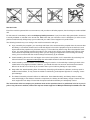
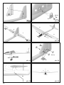
Hinweis: Bildseiten aus der Mitte der Bauanleitung heraustrennen!
1. Vor dem Bau
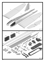
Prüfen Sie vor Baubeginn den Inhalt Ihres Baukastens.
Dazu sind die Abb. 1+2 und die Stückliste hilfreich.
2. Höhen- und Seitenruderservo vorbereiten
Die Servos mit einem Servotester / MULTImate oder der
Fernsteuerung in Neutralstellung bringen (Trimmung nicht
*Y
Servohebel mit Abtriebsbohrung Ø 1mm so montieren,
dass bei beiden Servos der Hebel 90° nach links zeigt.
Die Gestänge werden später in das erste Loch von innen
Q"
Y
*
%
Arme und der Überstand werden mit einem Seitenschneider abgeschnitten!
Abb. 03
Hinweis: Bei einigen Servohebeln ist die Verzahnung so
aufgeteilt. dass eine Feinjustierung möglich ist. Wenn der
Hebel also nicht genau 90° aufgesteckt werden kann, diesen dann um 180° gedreht montieren!
3. Servo im Servorahmen montieren
Das Servokabel durch den Servorahmen 43 stecken und
das Servo an den beiden Arretierlaschen einrasten.
Abb. 03
4. Servos in die Rumpfhälften kleben
An den Servorahmen 43 aussen Kleber anbringen und mit
den Servos in die Rumpfhälften kleben.
$
Q
'Y
/%
4 den Servohebel nach hinten und bei der linken Rumpfhälfte 3 nach
5
vorne positionieren.
Die Kabel in der Vertiefung nach vorne verlegen und gleich
"
"
/+"
|
"
später beim Verkleben der beiden Rumpfhälften nicht behindern.
Abb. 04+05
Hinweis: Sicher ist Ihnen aufgefallen, dass die Servokabel der Servos nun eingesperrt sind. Normalerweise werden Sie die Servos nicht mehr wechseln müssen, falls es
doch einmal einen Defekt geben sollte, können Sie den
Schaumsteg zwischen den Servos herausschneiden und
nach dem Servowechsel wieder einkleben.
5. Bowdenzüge vorbereiten
Die Bowdenzugrohre haben folgende Länge - ggf. kürzen:
Bowdenzugrohr HR Höhenruder 63
Ø2/1 x 470 mm
Bowdenzugrohr SR Seitenruder 64
Ø2/1 x 500 mm
10. Motor in der Rumpfverkleidung befestigen
Mit dem Brushless Antriebssatz Panda Sport # 33 3662
incl. Akku ist das Modell bestens motorisiert.
Die Komponenten in diesem Antriebssatz sind aufeinander abgestimmt und erprobt. Falls Sie andere Akkus, Regler, Motore oder Fernsteuerkomponenten einsetzen, liegt
dies in Ihrem Ermessen. Ein Support von unserer Seite ist
dann jedoch nicht möglich.
Hinweis: Zum Kürzen der Bowdenzugrohre das Klingenmesser auf dem Bowdenzugrohr abrollen und dabei anritzen. An dieser Stelle abbrechen - die Schnittkante ist
dann nicht gequetscht und der Stahldraht bewegt sich
leichtgängig!
6. Stahldrähte vorbereiten
Die Stahldrähte haben folgende Länge - ggf. kürzen:
Stahldraht HR Höhenruder 61 Ø1 x 535 mm
Stahldraht SR Seitenruder 62
Ø1 x 565 mm
Nun Draht 61 in Rohr 63 stecken - jeweils die langen Teile.
Ebenso Draht 62 in Rohr 64 stecken - jeweils die kurzen.
7. Bowdenzüge im Rumpf verlegen
In der rechten Rumpfhälfte 4 den langen Draht 62 für
das Seitenruder mit der Z-Biegung im rechten Servohebel einhängen. Draht und Bowdenzugrohr soweit biegen,
dass es am Rumpfende durch die Durchführung geschoben werden kann. Das Rohr so positionieren dass es am
Schaumsteg direkt hinter dem Servo beginnt. Das Rohr
+
%
6
|
"
es nicht herausfällt. Das Verkleben erfolgt später zusammen mit dem Aluminium 4-kt. Rohr.
Abb. 06
In der linken Rumpfhälfte 3 den kürzeren Draht 61 im Servohebel einhängen. Hier das Bowdenzugrohr so positionieren, dass es am Rumpfende dort endet, wo sich die
Führung zur Hebelkammer des HLW-Hebels aufweitet.
Abb. 07
8. Rumpf-Verstärkungsrohr einbauen
Das 4-kt. Aluminium Rumpf-Verstärkungsrohr 65
QY
geradlinig und vollständig in die Aussparung in die rechte Rumpfhälfte 4 einkleben. Von hinten an der unteren
Rumpfkante entlangpeilen und sicherstellen dass der
Rumpf gerade ist.
Abb. 06
9. Rumpfhälften miteinander verkleben
Halten Sie die beiden Rumpfhälften 3+4 zunächst ohne
Klebstoff zusammen und prüfen Sie deren Passung. Erst
wenn alles exakt passt, werden die beiden Rumpfhälften
miteinander verklebt.
"6%
/%
"
am Aluminium Verstärkungsrohr 65 Klebstoff auftragen.
Dabei zu den Aussenkanten ca. 5mm einhalten, damit der
Klebstoff nicht nach aussen überquillt. Die Teile fügen und
geradlinig ausrichten. Bis zur Aushärtung ggf. mit einigen
Klebestreifen sichern. Von hinten an der unteren Rumpfnaht entlangpeilen und sicherstellen dass der Rumpf gerade ist und bleibt. Abb. 08
6
In die Rumpfverkleidung / Motorspant 42.1 den Elektromotor PERMAX BL-O 2812-1100 mit zwei der im Antriebssatz beiliegenden Schrauben M3x6mm und den Unterlegscheiben so befestigen, dass die Anschlusskabel auf der
Rumpfunterseite verlegt werden können.
Abb. 09
11. Rumpfverkleidung in den Rumpf kleben
Die Rumpfverkleidung 42.1 mit montiertem Motor passgenau vorne auf den Rumpf halten und zentriert ausrichten.
Am Besten lässt sich die mittige Ausrichtung kontrollieren wenn Sie den Rumpf von unten betrachten und sich
an der dahinterliegenden Rumpfaussparung orientieren.
Wenn alles passt, diesen vollständig aufgesteckt mit dem
Schaumteil verkleben. Diese Verklebung vollständig aushärten lassen - in der Zwischenzeit werden die Luftschraubenblätter am Propellermitnehmer montieren.
Abb. 10
12. Klapp-Luftschraubenblätter montieren
Schrauben Sie zunächst die Klappluftschraubenblät
|
85 mit den Zylinderschrauben 84
Q)
|
Y
und den M3 Stoppmuttern 83 an den Propellermitnehmer
80. Ziehen Sie die Schrauben so weit fest, dass die Luftschraubenblätter kein Spiel aufweisen, sich jedoch noch
leicht anklappen lassen.
Abb. 11
13. Rumpfrahmen im Rumpf einbauen
Den Rumpfrahmen 40.1
Q
/6Y
"
schmalen Stegen etwas zusammendrücken und noch
ohne Klebstoff unten im Rumpf einpassen. Die Stege vollständig an die Schaumteil-Seitenwand und in die eingeformte Nut drücken und den Rumpfdeckel 41.1 einrasten.
Wenn alles passt diesen Vorgang mit Klebstoff wiederholen. Zum Aushärten auf jeden Fall den Rumpfdeckel wieder einrasten, damit bis zur Aushärtung alles richtig positioniert ist.
Abb. 12
Hinweis: Durch Toleranzen bei der Fertigung kann es zur
besseren Optik notwendig sein, im hinteren Bereich des
Rumpfrahmens den Schaum minimal nachzuschneiden.
14. Fernsteuerungseinbau
Mit der Positionierung der Komponenten können Sie die
+6"
("
"
+
"
*
$"lastkugeln in die Löcher im Seitenleitwerk.
Den Regler MULTIcont BL-20 SD an den Anschlüssen
des Motors anstecken und ganz oben im Rumpf mit Klettband 20+21 befestigen. Der M-LINK
5%
Q/Y
+
im Freiraum hinter den Servos auf dem Rumpfboden befestigt. Die Antenne wird aus der Abluftöffnung geführt und
"
|
\
/
+
*
Antriebsakku Li-BATT FX 3/1-950 mit Klettband an der
Rumpfseitenwand befestigt. Die Kabel etwas ordnen und
z.B. mit Heisskleber oder Klebeband an der Rumpfwand
festlegen.
Abb. 13
Hinweis: Da die Klettkraft des Klettbandes besser als der
6
"
"%
%
wir das Klettband zusätzlich mit Heisskleber oder Zacki
ELAPOR ® festzukleben.
15. Erster Probelauf des Motors
Hinweis: Den Verbindungsstecker Antriebsakku / Reglererst einstecken, wenn Ihr Sender eingeschaltet ist und Sie
sicher sind, dass das Bedienelement für die Motorsteuerung auf „AUS“ steht!
In Verbindung mit Ihrer Fernsteuerung und dem An"66
(
Q
="Y
fen. In Flugrichtung gesehen, muss sich die Antriebswelle
\
Q
Y
"
Fall, vertauschen Sie zwei der drei Motoranschlusskabel.
16. Luftschraube und Spinner am Modell montieren
In den Propellermitnehmer 80 den Mitnehmer mit Spannkonus 82 einstecken. U-Scheibe 87, Zahnscheibe 88 und
Mutter 86 lose auf dem Gewinde montieren.
Abb. 11
Schieben Sie dann den gesamten Zusammenbau auf die
Motorwelle und achten Sie darauf, dass der Propellermitnehmer 80 ca. 1 mm Abstand zum Rumpf hat.
Die Mutter festziehen und sicherstellen, dass sich der Abstand beim Anziehen zwischen Propellermitnehmer und
Rumpf nicht verändert! Der Spinner 81 wird mit den beiden Schrauben 74 2,2 x 6,5 mm befestigt.
Abb. 14
17. Höhenleitwerkshebel vormontieren
Den Gestängeanschluss 25 durch die Bohrung des HLWHebels 50
6
Q$Y
\`
26 und Mutter 27 befestigen. Die Mutter nur mit den Fingern leicht aufschrauben (der Gestängeanschluß muss
"
Y
)
"
"ren Gewindestummel mit Schraubensicherung oder Klebstoff sichern. Den Inbus-Gewindestift 24 von der Stirnseite
mit dem Inbusschlüssel 28 in den Gestängeanschluss einschrauben.
Abb. 15
18. Seitenleitwerk fertigstellen
Am Seitenleitwerk 9 das Seitenruder durch mehrmaliges
hin- und herbiegen leichtgängig machen. Das „HLW-Lagergehäuse“ 46 in die Ausformung ins Seitenleitwerk kleben. Abb. 16
Hinweis: Achten Sie darauf, dass kein Klebstoff in die
$
="%
`
"
%
$
19. Ruderhorn für Seitenruder
In das „Ruderhorn Twin“ 22 den Kardanbolzen 23 einclipsen. Den Inbus-Gewindestift 24 in den Kardanbolzen eindrehen. Ruderhorn nach vorne gekippt in die Ausformung
des Seitenruders kleben.
Abb. 17
20. Fertigstellen des Höhenleitwerks
In die linke Höhenleitwerkshälfte 7 die „HLW Steckung mit
der Achse“ 48 einkleben. Abb. 18
In die rechte Höhenleitwerkshälfte 8 die „HLW Steckung
mit Arretierung“ 49 einkleben und hier nur soviel Klebstoff
auftragen, dass dieser nicht nach innen läuft.
Abb. 19
Hinweis: Vor dem Zusammenstecken der Leitwerke die
Klebungen solange aushärten lassen, bis der Kleber sicher getrocknet ist - sonst bekommen Sie das Leitwerk
u.U. nicht mehr auseinander!
Zur Demontage drücken Sie auf die mit „X“ gekennzeichnete Stelle am Leitwerk 8 um die Arretierung zu lösen.
Abb. 19
21. Vorbereitung der Holmrohre
Den Holmverbinder 44 mit wenig Klebstoff bis zum Anschlag auf das Aluminium Holmrohr 60
QY
6
In die seitliche Bohrung im Holmverbinder die BlechLinsenschraube 31 ansetzen und mit einen passenden
"
Q
Y
kräftigem Druck bis zum Anschlag eindrehen. Ggf. kann
das Aluminium auch mit Ø1,5mm vorgebohrt werden. Die
Einbaurichtung des Holmverbinders ist egal, da das Teil
symmetrisch ist.
Abb. 20
<"%
6, in die Aussparung für den
"
%
&+
?"6
5=;8/
auftragen. Das Holmrohr mit dem Holmverbinder vollständig und passgenau eindrücken.
Abb. 21+22
6
<"%
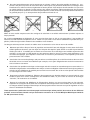
5 das Holmrohr 60 mit lose aufgesteckter Flächenarretierung 45 entsprechend in den Flügel kleben. Darauf achten, dass die Flächenarretierung 45
noch nicht mit dem Holm bzw. dem Schaum verklebt wird
sondern sich noch leicht verschieben lässt.
Die Flächenarretierung 45 wird erst nach dem zusammen"
<"%
/
Position am Holm verklebt.
Abb. 23+24
(
<"%
/
"6
Das Modell dabei auf den Rücken legen und bei vollstän
"6
<"%
Flächenarretierung 45 so in der Verzahnung einrasten,
dass noch ein Spalt zwischen den beiden Kunststoff
Q"
{
?%Y
;
*
nur an der im Bild gezeigten Position sparsam Zacki ELAPOR Super liquid
"
|
9"
erster Aushärtung das Modell auseinanderbauen und die
Flächenarretierung ggf. nachkleben. Zur Demontage der
<"%
="
'
"
*
7
Flügelvorderkante ziehen, bis die Verzahnung geöffnet ist.
Abb. 25
Motordrehrichtung jetzt zusammen mit dem Propeller.
Abb. 30 + 34
Hinweis: Wird später beim Betrieb des Modells die Ar
<"%
6"
sammendrücken um einen Zahn wieder ein sicherer Halt
erfolgen.
28. Ruderausschläge einstellen (Richtwerte!)
Um eine ausgewogene Steuerfolgsamkeit des Modells zu
erzielen, ist die Größe der Ruderausschläge richtig einzustellen. Die Ausschläge werden jeweils an der tiefsten Stelle
der Ruder gemessen.
24. Höhenleitwerkshebel im Rumpf einbauen
Den Höhenruder-Servohebel nach vorne drehen um hinten am Stahldraht etwas Freiraum zu schaffen. Nun hinten
den um 90° gedrehten HLW-Hebel 50 in die Aussparung
stecken und erneut um 90° drehen und dabei den Stahldraht in den Gestängeanschluss 25 einfädeln. Dann vorne
den Servohebel wieder in Neutralstellung bringen und den
Gestängeanschluss mit dem Inbusschlüssel durch das
seitliche Loch im Rumpf festklemmen.
Abb. 26
25. Seitenleitwerk auf den Rumpf kleben
Das Seitenleitwerk 9 zunächst ohne Klebstoff auf dem
Rumpf anpassen. Die Zapfen des Leitwerks schräg in den
Rumpf stecken, das Leitwerk kippen und den aus dem
Rumpf hervorstehenden Hebel im Lagergehäuse 46 positionieren. Wenn alles passt diesen Schritt mit Zacki ELAPOR wiederholen und das Leitwerk sorgfältig zum Rumpf
ausrichten.
Abb. 27
Hinweis:
Zum Ausrichten des Seitenleitwerks empfehlen wir die
<"%
/
"6
kann von vorne gepeilt das Leitwerk entsprechend ausgerichtet werden.
Abb. 34
26. HLW-Hebel im Lagergehäuse montieren
Nun in das Lagergehäuse 46 den HLW-Hebel 50 einsetzen. Das Gehäuse mit dem Deckel 47 und den Schrauben
29 M2x10mm verschließen. Leichtgängigkeit prüfen und
ggf. nacharbeiten.
Abb. 28
Nun das Höhenleitwerk probeweise am Rumpf montieren.
Schieben Sie dazu die beiden Höhenleitwerkshälften so
weit zusammen dass diese verriegeln.
Abb. 29
Hinweis: Achten Sie darauf, dass sich das Leitwerk leichtgängig bewegen lässt. Ggf. kann es notwendig sein den
Schaum an der Stirnseite der Leitwerke geringfügig zusammenzudrücken. Dies funktioniert am einfachsten wenn
Sie die Leitwerkshälfte mit der Stirnseite auf die Tischkante stellen und unter mässigem Druck hin und herschieben.
Der Schaum kann auch mit dem Messer minimal nachgeschnitten werden.
27. Kontrolle des Modells
Vergewissern Sie sich, dass das Modell gerade ist und alle
Fernsteuerungskomponenten richtig eingebaut und angeschlossen sind. Prüfen Sie Rudereinstellungen, Drehrichtungen der Servos und Freigängigkeit der Rudermechaniken. Achten Sie darauf, dass die Anschlusskabel nicht in
den sich drehenden Motor bzw. Servohebel gelangen kön
Q'6Y^
;
"
"
*
8
Höhenruder:
Seitenruder:
10 / 10 mm +/15 / 15 mm +/-
Das Höhenleitwerk steht neutral, wenn durch die seitliche
Öffnung im Rumpf der Inbus-Gewindestift zu sehen ist.
Bevor Sie hier den Gewindestift anziehen stellen Sie das
Höhenruderservo genau auf Neutral!
Abb. 33
29. Dekor anbringen
Dem Bausatz liegt ein Dekorbogen 2.2 bei. Die einzelnen
Schriftzüge und Embleme sind bereits ausgeschnitten und
+
"
#"
Q$"6"Y
"
eigenen Vorstellungen aufgeklebt.
Achtung: Die runden Punkte werden später nach dem
Auswiegen des Schwerpunkts zum Verschliessen der Ballastkammern benötigt - diese also nicht wegwerfen!
Für die eigene farbliche Gestaltung empfehlen wir unser
"
5=;8/
{
`
{{
Q#"
)\=<;
{
Y
30. Kabinenhaube einfärben
Die Kabinenhaube wird entweder mit einem wasserfesten
Filzschreiber bis zum Rand geschwärzt oder abgeklebt
$
"
'"
Q
{Y
"
timent lackiert.
Tipps zur Lackierung mit „ELAPOR® Color“ Sprühfarben
"
"
7
'
31. Schwerpunkt auswiegen
Mit der Position des Reglers, Flugakkus und ggf. etwas
Zusatzballast wird der Schwerpunkt eingestellt. Dieser
liegt 55 mm von der “Flügelnase” am Rumpf nach hinten gemessen. Die Position ist mit kleinen Warzen auf der
\
<"%
"6
'
terstützt das Modell so auspendeln, dass die Rumpfnase
ganz leicht nach unten zeigt.
Der Zusatzballast 30 wird in die Kammern eingefüllt und
mit den runden Aufklebern vom Dekorbogen abgedeckt.
Abb. 32
"$%
'
5
+"
>
+
Tag ab. Besonders günstig sind oft die Abendstunden.
7
6
5"
)
"
chen Sie sich einen geübten Helfer. Ganz allein geht es
+"
"6
>
)*
9"
6>
Ihren Händler befragen.
Vor dem ersten Flug unbedingt einen Reichweitentest
durchführen! Halten Sie sich dabei an die Vorgaben des
Herstellers Ihrer Fernsteuerung!
Sender- und Flugakku sind frisch und vorschriftsmäßig
geladen. Vor dem Einschalten des Senders sicherstellen,
dass der verwendete Kanal frei ist, sofern keine 2,4 GHzAnlage verwendet wird.
Falls etwas unklar ist, sollte auf keinen Fall ein Start erfolgen. Geben Sie die gesamte Anlage (mit Akku, Schalterka
*Y
*"
%
zur Überprüfung.
%'
Das Modell wird aus der Hand mit laufendem Motor gestar
Q
7
+^Y
Machen Sie sich in ausreichender Höhe vertraut, wie das
Modell reagiert, wenn der Motor ausgeschaltet ist. Trimmen
"
)
"
"
""
gleichmässige Fluggeschwindigkeit beibehält.
&
'"
=""
"der Höhe, so sind Sie vorbereitet, wenn der Antriebsakku
leer wird.
Versuchen Sie in der Anfangsphase, insbesondere bei der
Landung, keine „Gewaltkurven“ dicht über dem Boden.
Landen Sie sicher und nehmen besser ein paar Schritte
in Kauf, als mit Ihrem Modell bei der Landung einen Bruch
zu riskieren.
34. Flug am Hang
(
"
*
)
'
"+
>
mit zu den schönsten Erlebnissen. Die Krönung ist das
<6
*
"
"
("
)
"+
"
"
<"
<6
<6
hochkreisen bis an die Sichtgrenze (Vorsicht das Modell
6^Y
"
)
+
"
+
)
Vollendung. Durch den Elektroantrieb kann das Modell bei
"
+
&
+
6
werden. Das Risiko das Modell bei einer Aussenlandung
im Tal zu beschädigen ist somit nicht gegeben.
36. Sicherheit
Sicherheit ist das oberste Gebot beim Fliegen mit Flug
5
"*
"
Falls Sie in einen Verein oder Verband eintreten, können
Sie diese Versicherung dort abschließen. Achten Sie auf
"
#
Q)
Y
"
)
'
absolut in Ordnung. Informieren Sie sich über die Ladetechnik für die von Ihnen verwendeten Akkus. Benutzen
Sie alle sinnvollen Sicherheitseinrichtungen, die angeboten
werden. Informieren Sie sich in unserem Hauptkatalog oder
auf unserer Homepage www.multiplexrc.de
)\=<;=5`;6
*
"
)
aus der Praxis für die Praxis gemacht. Fliegen Sie verantwortungsbewusst! Anderen Leuten dicht über die Köpfe zu
6
?
+6
>
+6
Könner hat dies nicht nötig. Weisen Sie auch andere Piloten
in unser aller Interesse auf diese Tatsache hin. Fliegen Sie
immer so, dass weder Sie noch andere in Gefahr kommen.
Denken Sie immer daran, dass auch die allerbeste Fern
&
%@
5
>
+
kann. Auch langjährige, unfallfreie Flugpraxis ist keine
Garantie für die nächste Flugminute.
Prüfen Sie vor jedem Start den sicheren Sitz des Akkus,
der Flügel und Leitwerke. Kontrollieren Sie auch die
Funktion aller Ruder!
Wir, das MULTIPLEX -Team, wünschen Ihnen beim Bauen
und später beim Fliegen viel Freude und Erfolg.
MULTIPLEX Modellsport GmbH & Co. KG
35. Lehrer / Schüler Betrieb
Der Panda / Panda Sport ist aufgrund seiner gutmütigen
Flugeigenschaften und der langen Flugzeit auch ideal als
)
6"
'6`
Lehrer-Schüler Stick # 4 5183, zwei MULTIPLEX Sendern
und einem geübten Lehrer kann der Schüler das Fliegen
materialschonend erlernen. Nach kurzer Zeit wird der
Schüler das Modell selbstständig steuern können.
Als Schüler-Sender können alle Sender mit 2,4 GHz MLINK Technologie verwendet werden. Als Lehrer-Sender
eignen sich alle MULTIPLEX-Sender mit DIN-Multifunktionsbuchse und Lehrer-Funktionalität, gleichgültig ob
2,4 GHz M-LINK*- oder xx MHz-Ausrüstung. Lehrer und
Schüler können bei Bedarf auch 20 – 30 Meter voneinander entfernt stehen und es gibt keine Behinderung wegen
des Verbindungskabels mehr.
9
D
Erhältliche Varianten
# 21 4268
# 26 4268
# *26 4272
# 26 4269
# 1 3268
# 1 3269
KIT
RR
*RR+
RR+
RTF
RTF
Panda Sport
Panda Sport
Panda Sport
Panda
Panda Mode 1 und 3
Panda Mode 2 und 4
QY Baukasten
Q*
)
$=`8
{{`Y
QY Fertigmodell, Servos, Regler, Motor BL-O 2812-1100
QY Fertigmodell, Servos, Regler, Motor BL-O 2812-1100, Empfänger, Akku
Q"Y Fertigmodell, Servos, Regler / Empfänger, Motor 400 6V, Akku
Q"Y Fertigm. Servos, Regler / Empfänger, Motor 400 6V, Sender, Akku, Ladegerät
Q"Y
Fertigm. Servos, Regler / Empfänger, Motor 400 6V, Sender, Akku, Ladegerät
Mit einem farbigen Textmarker können Sie sich zur besseren Übersicht ihre Variante in der untenstehenden Stückliste markieren!
Stückliste Panda / *Panda Sport
Lfd. Stückzahl
KIT RR RR+ RTF
1
1
1
1
1
1.1 0
1
0
0
1.2 0
0
1
0
1.3 0
0
0
1
1.4 0
1 *1/0
0
1.5 0
1 *1/0
0
1.7 1
1
1
1
2.1
¥q
2.2
¥q
3
1
1
1
1
4
1
1
1
1
5
6
7
1
1
1
1
8
1
1
1
1
9
1
1
1
1
Bezeichnung
Material
Abmessungen
Bauanleitung KIT
Zusatzanleitung RR
Zusatzanleitung RR+
Zusatzanleitung RTF
Anleitung Antriebssatz "Panda SPORT"
Anleitung BL-Regler
Reklamationsbearbeitung Modelle
(6
;""
Q"Y
(6
;""
QY
Rumpfhälfte links
Rumpfhälfte rechts
<"%
6
<"%
Höhenleitwerk links
Höhenleitwerk rechts
Seitenleitwerk
6
6
Elapor geschäumt
Elapor geschäumt
5"
%
5"
%
Elapor geschäumt
Elapor geschäumt
Elapor geschäumt
|
|
KIT RR RR+ RTF
20 3
3
3
3
21 3
3
3
3
22 1
1
1
1
23 1
1
1
1
24 2
2
2
2
25 1
1
1
1
26 1
1
1
1
27 1
1
1
1
28 1
1
1
1
29
{
{
{
{
30 50 50 50 50
31
Kleinteilesatz Q
"
<Y
Klettband Pilzkopf
Klettband Velours
Ruderhorn "Twin"
Kardanbolzen
Inbus-Gewindestift
Gestängeanschluß
U-Scheibe
Mutter
Inbusschlüssel
6"
Q="6Y
Trimmgewicht
$`="
Q*Y
Kunststoff
Kunststoff
Kunststoff
Metall
Metall
Metall
Metall
Metall
Metall
)"
Metallkugel
)"
25 x 60mm
25 x 60mm
Fertigteil
Fertigteil Ø6mm
M3 x 3mm
Fertigteil Ø6mm
M2
M2
SW 1,5
){
|
Ø 4mm / ca.15g
{{
|
KIT RR RR+ RTF
40
¥q
40.1
¥q
41
¥q
41.1
¥q
42
¥q
42.1
¥q
43 2
2
2
2
44 1
1
1
1
45 1
1
1
1
46 1
1
1
1
47 1
1
1
1
48 1
1
1
1
49 1
1
1
1
50 1
1
1
1
Kunststoffteilesatz Q
"
<Y
/"
Q"Y
/"
QY
/6
Q"Y
/6
QY
/*6
Q"Y
)"
/*6
QY
)"
Servorahmen "Nano" stehend
Kunststoff
Holmverbinder
Kunststoff
Flächenarretierung
Kunststoff
HLW Lagergehäuse
Kunststoff
HLW Lagerdeckel
Kunststoff
HLW Steckung mit Achse
Kunststoff
HLW Steckung mit Arretierung
Kunststoff
HLW Hebel
Kunststoff
'
'
'
'
'
'
Fertigteil
Fertigteil
Fertigteil
Fertigteil
Fertigteil
Fertigteil
Fertigteil
Fertigteil
KIT RR RR+ RTF
{
{
{
{
1
1
1
1
1
1
1
1
1
1
1
1
1
1
1
1
Drahtsatz und Holme Q
"
<Y
<"%
=\``6
Stahldraht für HR m. Z.
Metall
Stahldraht für SR m. Z.
Metall
$+
/
Bowdenzugrohr SR
Kunststoff
Rumpf.Verstärkungsrohr
ALU-4-kt.
|
|
Ø0.8 x 535mm
Ø0.8 x 565mm
{q
|
Ø2/1 x 500mm
8 x 6 x 380mm
60
61
62
63
64
65
10
Lfd. Stückzahl
KIT RR RR+ RTF
70
¥q
71
¥q
72 0
0 *0/1
1
73 0
0 *0/2
2
74 2
2
2
2
75 0
0 *0/2
2
Bezeichnung
Propeller, Mitnehmer, Spinner Panda
;
Q;""Y
"
Q;""Y
"
Mitnehmer mit Spannkonus
Klappluftschraubenblatt
Blech-Linsenschraube
Senkschraube
Material
Abmessungen
Metall
Kunststoff
Metall
Metall
'
Ø2,3 / M6 / 6kt SW13
6 x 3"
Ø 2,2 x 6,5mm
M2 x 12mm
80
81
82
83
84
85
86
87
88
KIT RR RR+ RTF
¥q
¥q
1
1 *1/0
0
2
2 *1/0
0
2
2 *1/0
0
{
{
¥q
1
1
1
1
1
1
1
1
1
1
1
1
Propeller, Mitnehmer, Spinner-Set Panda Sport Q
//Y
;
;""
QY
;""
QY
Mitnehmer mit Spannkonus
Metall
Stoppmutter
Metall
Zylinderschraube
Metall
"""
Mutter
Metall
U-Scheibe
Metall
Zahnscheibe
Federstahl
90
91
KIT
0
0
Servos für Rumpf Q
"
<Y
Servo für Seitenruder
Nano-S
Servo für Höhenruder
Nano-S
96
98
KIT RR RR+ RTF
¥q
0
1 *1/0
0
{
¥q
0
0 *1/0
1
RR RR+ RTF
1
1
1
1
1
1
'
Ø3,2 / M6 / 6kt SW13
M3
M3 x 18mm
|
¦
M6 DIN 934
Øi 6,4
Øi 6,4
Antrieb PERMAX BL-O 2812-1100 für Panda Sport Q
//Y
Q7`Y
;5/)
$=`8
{{`
Regler
MULTIcont BL-20 SD
?"
Q
)Y
)"
)
|
Empfänger
RX-3 cont M-Link ID 8
KIT RR RR+ RTF
101 0
0
1
1
{
{
{
Antrieb PERMAX 400 6V für Panda Q
//}
/<'Y
Q7`{Y
;"|
#
Empfänger / Regler Einheit
RX-5 M-Link ID 10
?"
Q
)Y
)"
KIT RR RR+ RTF
¥q
¥q
Akkus
66
;5/)
#
66
;5/)
$=`8
{{`
KIT RR RR+ RTF
105 0
0
0
1
106 0
0
0
1
108 0
0
0
1
Sender, Ladegerät und Zubehör
Sender
Sender
$"
Q
;"6Y
Anleitung Smart SX
="%
){
|
=`$<<
'
{q`
Q)Y
Panda
=`$<<
'
q`
Q)Y
Panda Sport
Smart SX Mode 1/3
Smart SX Mode 2/4
#
)\=<"
=`
5\
11
Safety Information for MULTIPLEX model aircraft
This model is NOT A TOY in the usual sense of the term.
GB
$
"
+
"
"
"+"
"
"
+
"
""
"
"
"
"
""
¨
This model must not be operated by any child under fourteen years of age. If a person below this age operates the model
under the supervision of a competent adult who is acting as the child’s guardian within the legal sense of the term, this
individual is responsible for the implementation of the information in the OPERATING INSTRUCTIONS.
THE MODEL AND ASSOCIATED ACCESSORIES MUST BE KEPT OUT OF THE REACH OF CHILDREN UNDER THREE
YEARS OF AGE! MODELS CONTAIN SMALL DETACHABLE PARTS WHICH MAY BE SWALLOWED BY CHILDREN
UNDER THREE YEARS. CHOKING HAZARD!
All the warnings in the OPERATING INSTRUCTIONS must be observed whenever the model is operated. Multiplex
Modellsport GmbH & Co. KG accepts no liability for loss or damage or any kind which occurs as a result of incorrect
operation or misuse of this product, including the accessories required for its operation. This includes direct, indirect,
deliberate and accidental loss and damage, and all forms of consequent damage.
Every safety note in these instructions must always be observed, as all the information contributes to the safe operation of your model. Use your model thoughtfully and cautiously, and it will give you and your spectators many hours of
"
+
"
""
'"
"
"
"
"
"
property damage and severe personal injury. You alone bear the responsibility for the implementation of the operating
instructions and the safety notes.
Approved usage
The model is approved exclusively for use within the modelling hobby. It is prohibited to use the model for any other
purpose than that stated. The operator of the model, and not the manufacturer, is responsible for damage or injury of
any kind resulting from non-approved use.
The model may only be operated in conjunction with those accessories which we expressly recommend. The recommended components have undergone thorough testing, are an accurate match to the model, and ensure that it functions
safely. If you use other components, or modify the model, you operate it at your own risk, and any claim under guarantee
is invalidated.
To minimise the risk when operating the model, please observe the following points:
zThe model is guided using a radio control system. No radio control system is immune to radio interference, and
such interference may result in loss of control of the model for a period of time. To avoid collisions, you must
therefore ensure at all times that there is a wide margin of safety in all directions when operating your model. At
the slightest sign of radio interference you must cease operating your model!
zNever operate your model until you have successfully completed a thorough check of the working systems, and
carried out a range-check as stipulated in the instructions supplied with your transmitter.
z<
"
+
*
«
"
"*
"
+"
z
*
"
"
+
"
"
+
have an adverse effect on visual acuity and reaction time.
z8
+
"
+"
+
"
"
""
Even when the wind is light, bear in mind that turbulence can form at and around objects which may have an
effect on the model.
z9*
"
"
+
"
"
"
""
*"
cables, open roads and railway lines.
z9*
+"
""
«
"
6
"
+
*
¬
"
piloting skill, but all it does is place others at unnecessary risk. It is in all our interests that you let other pilots
6+
"
+"
6
+"
"
+"
"
"
$"
mind that even the best RC system in the world is subject to outside interference. No matter how many years of
"`
"*
"*
"
+"
+
"
|
12
GB
Residual risks
Even if the model is operated in the correct manner, and you observe all safety aspects, there is always a certain residual
risk.
For this reason it is mandatory to take out third-party liability insurance
&
"
""
"
is usually available or included in the annual fee. Make sure that your insurance cover is adequate (i.e. that it covers
+
""Y
+"
6
"
"
¨
The following hazards may occur owing to the model’s construction and type:
zInjury caused by the propeller: you must keep well clear of the area around the propeller from the moment that
the battery is connected. Please bear in mind that objects in front of the propeller may be sucked into it, and
objects behind the propeller may be blown away by it. The model may start moving when the propeller starts
to turn. You must therefore position the model in such a way that it cannot move towards other persons if the
motor should unexpectedly start running. When you are carrying out adjustment work involving the running
motor, you must ensure that the model is always held securely by an assistant.
z"
"
[
"
"
*
"
|*
"
safe environment: an "*
and suitable insurance are basic essentials.
zCrash caused by technical failure or unnoticed damage in transit or in the workshop. A thorough check of the
*
"
+*
"
"6
"
"
"
"
""
"
"
"
9*
"
"
+
"
""
&
z
+
"
"
5|*
*
+
+"6
""
"
"
""
"
"
"
"
"
¨
quent damage.
zFire hazard caused by electronic failure or malfunction. Store batteries safely, and always observe safety
notes which apply to the airborne electronic components, the battery and the battery charger. Protect all electronic equipment from damp. Ensure that the speed controller and battery are adequately cooled.
The instructions which accompany our products must not be reproduced and / or published, in full or in part, in
print or any electronic medium, without the express written approval of Multiplex Modellsport GmbH & Co. KG.
13
KIT Panda Sport
GB
# 21 4268
Examine your kit carefully!
MULTIPLEX model kits are subject to constant quality checks throughout the production process, and we sincerely hope
"
"
"
+
6
+*
+
+
"6
6
"
"
Q
;"
=Y
"
"
+
"
|"
+
"*
""
"
"
""
"
"
+
+
"
"
¨
+
have inspected it. Please send the component to our Service Department, with adequate postage pre-paid, being sure to
include the completed complaints form. We are constantly working on improvements to our models, and for this reason
we must reserve the right to change the kit contents in terms of shape or dimensions of parts, technology, materials and
+
"
;"
"
"
+
"
"
"
""
6
agree in every respect with the instructions and the illustrations.
Caution!
Radio-controlled models, and especially model aircraft, are by no means playthings in the usual sense of the
term. Building and operating them safely requires a certain level of technical competence and manual skill,
;
<=
5
"
"
"
"
"
&
"
""
Since we, as manufacturers, have no control over the construction, maintenance and operation of our products, we are
obliged to take this opportunity to point out these hazards and to emphasise your personal responsibility.
Warning:
Like every aeroplane, this model has static limits. Steep dives and senseless manoeuvres inappropriate to the type
may result in the loss of the aircraft. Please note: we will not replace the model in such cases. It is your responsibility to
approach the airframe’s limits gradually. It is designed for the power system recommended in these instructions, but is
""
+"
"
|"
"
"
"
""
"
Airborne radio control system components / other accessories
Recommended equipment:
MULTIPLEX receiver, min. RX-5 light M-LINK
Order No. 5 5808
or
RX-5 M-LINK receiver, telemetry-capable
Order No. 5 5817
With this receiver you can also use the telemetry modules, and equip your model
+
"
*"
q
"
"
Q
"Y
Servos
{
|
9"`
*
Q*"
}
Y
or
{
|
9"
;
)
*
Q*"
}
Y
~
+
"
"|
8
9
6 5120
8
9
6 5119
>;
<?
“Panda Sport” power set, Li-BATT powered
Order No. 33 3662
containing PERMAX BL-O 2812-1100 brushless motor,
)\=<
$=`{
(
=`$<<
'
q`
Q)Y
"
~
*
"
|
6
"
""^
Power set:
“Panda Sport” power set
Order No. 33 2662
containing PERMAX BL-O 2812-1100 brushless motor, MULTIcont BL-20 SD speed controller,
~
*
"
|
6
"
""^
Recommended battery:
=`$<<
'
q`
Q)Y
"
~
;""
^
8
9
15 7321
Adhesives:
Zacki ELAPOR ® 20 g
Zacki ELAPOR ® Super liquid 10 g
Order No. 59 2727
Order No. 59 2728
Battery charger:
MULTIcharger LN-3008 EQU and AC / DC 230V / 12V 5.0A PSU combo
Order No. 9 2545
Tools:
Balsa knife, various slot-head and cross-point screwdrivers, 10 mm A/F open-ended or socket spanner.
Model Service Box
14
Order No. 8 5500
Important note
This model is not made of Styrofoam™, and it is not possible to glue the material using white glue, polyurethane or
|]
"*
"
&
"
"6
"+"
;"
`*
"`""
|*
"
?"6
5=;8/
{{
+
"
for ELAPOR® particle foam. If you se Zacki ELAPOR® there is usually no need for cyano ‘kicker’ or activator. However,
if you wish to use a different adhesive which requires the use of activator, please note that these materials are injurious
to health, and should always be applied in the open air. Take care when handling all cyano-acrylate adhesives, as they
"
¬
"
7
goggles to protect your eyes. Keep the adhesive out of the reach of children! For certain joints it is also possible to use
`
"*]
"
+
"
Working with Zacki ELAPOR®
?"6
5=;8/
"
*
"
&
+
5=;8/
foam parts.
Please observe the following points in order to obtain perfect joints:
7
"*
"*
&
"
{
"
"|
""
+
""
"
*"
"
"`""
&
Q±"6¬Y
"
"
"*"
"
"
allow it to air-dry for about thirty seconds.
<
"
"|
&
"
"
+
{`
""*
"
"
<
"*
+
"
¨6
"
*
]
"
"*"
Q66Y
not required. All you have to do is moisten the mating surface very lightly with a damp cloth or sponge.
@J<QY[<=
\
\
it is easy to straighten again. In this respect ELAPOR® behaves in a similar way to metal: bend the component
back slightly beyond the correct position, and the material will then spring back to its proper shape when released,
and maintain it. There are limits, however - don’t overdo it!
Bent parts - really do exist.
+
"
"
);
;
{
"
+
very lightly as if you were cleaning the model. Paint must always be applied thinly and evenly, otherwise the component
will warp. Then you really will have bent parts, and they will also be heavy and perhaps even unusable. We have found
"
"`
"
*"
7
5=;8/
"
"
"
{
`
{{
Q"
*
"
"
)\=<;
{
"Y
]=?
Wingspan
Overall length
`
+
7
""
7
"
>
1160 mm
800 mm
"|
Q'Y
{
q
>]
1160 mm
800 mm
{
"|
Q'Y
{
q
RC functions:
Elevator, rudder, throttle
The Centre of Gravity should be located 55 mm aft of the root leading edge of the wing. The position is indicated by
small pimples on the underside of both wing roots.
Note: please separate the illustration pages from the centre of the building instructions.
1. Before starting construction
Check the contents of your kit before starting work on the
«
+
Figs. 1 + 2 and the Parts List helpful
at this stage.
2. Preparing the elevator and rudder servos
*
"
QY
"
*
"
MULTImate or your RC system transmitter (don’t forget to
Y
Locate the servo output levers with 1 mm Ø output holes,
"
*
"
²
"
case. At a later stage the pushrods will be connected to
Q*
"|
Y
All the other arms can be cut off using side-cutters, as can
the excess length of the remaining arm.
Fig. 03
Note: the splines of some servo output levers are designed
"+
"&
"
*
output shaft at exactly 90°, turn it through 180° and try again.
3. Installing the servos in the servo mounts
Slip the servo lead through the servo mount 43, then push
the servo down into the frame so that the two retaining clips
snap over the servo mounting lugs.
Fig. 03
15
4. Gluing the servos in the fuselage shells
Apply glue to the outside faces of the servo mounts 43,
"
`
+
*
`
"
as shown.
Note that the output shaft of the servo in the right-hand
fuselage shell 4 Q"
"Y
"
"]
"
*
`"
"
shell 3 should be at the front.
Deploy the servo leads in the appropriate channels, running
"
+"
"
"
"
*
|
"
to the fuselage sides, so that they cannot get in the way
when the two fuselage shells are joined. Figs. 04 + 05
5. Preparing the control snakes
Cut down the snake sleeves to the following length:
Elevator snake 63
2 Ø / 1 Ø x 470 mm
Rudder snake 64
2 Ø / 1 Ø x 500 mm
Note: the best way to shorten the snake sleeves is to
hold a balsa knife in the correct position, and then roll the
*
"
""]
*
"
be snapped at the scored point. This procedure does not
distort or squash the sleeve, ensuring that the steel inner
pushrod will slide smoothly.
6. Preparing the steel pushrods
Cut down the steel inner pushrods to the following length:
Elevator pushrod 61
1 Ø x 535 mm
Rudder pushrod 62
1 Ø x 565 mm
Now slip the pushrod 61 in the sleeve 63 - both parts are
the longer versions. Slip the rod 62 in the sleeve 64 - both
parts are the shorter versions.
7. Deploying the control snakes in the fuselage
Start with the right-hand fuselage shell 4: connect the pre
QY
62 to the righthand servo output arm. Now gently bend the pushrod and
snake sleeve to the point where they can be slipped through
the slot in the tail end of the fuselage. Position the sleeve so
that it ends at the foam block immediately aft of the servo.
Tack the sleeve in place initially with a few drops of glue,
so that it cannot fall out. It is glued in place permanently at
a later stage, when the square aluminium tube is installed.
Fig. 06
Continue with the left-hand fuselage shell 3: connect the
shorter pushrod 61 to the servo output arm. In this case
position the snake sleeve so that it ends at the point where
the channel opens out into the tailplane crank chamber at
the tail end of the fuselage.
Fig. 07
8. Installing the fuselage stiffener tube
Locate the square aluminium fuselage stiffener tube 65
Q
Y
"
"
`"
fuselage shell 4, pushing it full-depth into the channel. Take
care to keep it perfectly straight: sight along the bottom
edge of the fuselage from the tail end, and ensure that the
fuselage is dead straight.
Fig. 06
9. Joining the two fuselage shells
Hold the two fuselage shells 3 + 4 together “dry” (without
16
Y
"
6
"
"
"
(
"
"
*
properly.
Apply adhesive to the contact surfaces of the fuselage
shells and the aluminium stiffener tube 65, leaving a gap
about 5 mm wide at the outside edges, so that the glue is
not forced out of the joints. Place the parts together and
set the fuselage exactly straight. Apply a few strips of tape
across the joints while the glue is hardening. Sight along
the bottom edge of the fuselage joint seam from the tail end
to check that the fuselage really is straight.
Fig. 08
Note: you will surely have noticed that the servo leads are
now permanently trapped. Normally you will never have to
replace a servo, but if this should prove necessary, you can
cut away the foam block between the servos, then glue it
back in place after installing the replacement.
10. Installing the motor in the fuselage nose fairing
The Panda Sport brushless power set # 33 3662 includes a
suitable rechargeable battery, and forms the perfect power
system for the model.
The components supplied in this power set have been
extensively tested, and are accurately matched to each
other. If you prefer to use a different battery, speed controller,
motor or RC system components, that is up to you, but we
would then be unable to provide support if a problem were
to occur.
Fix the PERMAX BL-O 2812-1100 electric motor to the
fuselage nose fairing / motor bulkhead 42.1 using two of
the M3 x 6 mm machine screws and washers included in
+
]
"
motor wires on the underside of the fuselage.
Fig. 09
11. Gluing the nose fairing to the fuselage
Hold the nose fairing 42.1 - with motor attached - against
"
"
"]
exactly central. The best method of centring it accurately
is to look at the fuselage from the underside, and line up
the fairing with the cut-out in the fuselage located behind it.
7
"
"
*
the nose fairing to the foam fuselage, applying adhesive to
the whole of the contact area. Allow plenty of time for this
&
"
]
"
"
"
propeller blades and the prop driver.
Fig. 10
12. Assembling the folding propeller blades
'
+
|
"
85 to the
propeller hub 80 using the M3 x 18 mm cheesehead screws
84 and M3 self-locking nuts 83. Tighten the screws just to
+
QY
blades, but they still fold back smoothly.
Fig. 11
13. Installing the fuselage hatch frame in the fuselage
Locate the hatch frame 40.1
Q+
"
"
"Y
and squeeze the narrow rails together slightly so that it can
Q
Y
"
Press the rails fully against the foam sides and into the
`
"
"
"
"
41.1
7
"
"
*
remove the hatch and frame, apply glue to the outside
contact surfaces, and repeat the procedure. Don’t forget
to engage the fuselage hatch again while the glue is still
soft, so that everything is held in the correct position while
the adhesive sets hard.
Fig. 12
Note: production tolerances may make it necessary to cut
away the foam very slightly where the rear of the hatch
"
"
"
"
14. Installing the receiving system components
The positioning of the RC components has a minor but
useful effect on the model’s Centre of Gravity. Final
""
"
"
""
Q"
"Y
Connect the MULTIcont BL-20 SD speed controller to the
+
""
"
|
|
top of the fuselage using the hook-and-loop tape 20 +
21. Install the M-LINK
*
Q/Y
fuselage, in the empty space aft of the servos. Route the
aerial out of the cooling air exit opening, and tape it to the
fuselage. The Li-BATT FX 3/1-950
"
"
|
to the fuselage side at the front, below the speed controller,
again using hook-and-loop tape. Group the cables together
"
"
|
"
`
adhesive or adhesive tape.
Fig. 13
Note: since the “grip” of the hook-and-loop tape is greater
than the adhesion between the sticky coating and the foam
surface, we recommend gluing the tape in place using hot
"*
?"6
5=;8/
Q"`""Y
15. Initial test-run of the motor
Note:
"
until you have switched on your transmitter, and are certain
that the control which operates the motor is at the “OFF”
position.
7
6
of rotation of the motor using your radio control transmitter
"
"[
+
*+
"
"
6+
Q
Y
"
"
swap over any two of the three wires attached to the motor.
16. Mounting the propeller and spinner on the model
Press the prop driver and taper collet 82 into the propeller
hub 80. Fit the washer 87, shakeproof washer 88 and M6
nut 86 loosely on the threaded shaft.
Fig. 11
Now slide the whole assembly onto the motor shaft, and
set a clearance gap of about 1 mm between the back of the
propeller hub 80 and the front face of the fuselage.
Tighten the nut, and check once more that the clearance
between prop driver and fuselage has not changed since
you wielded the spanner! Attach the spinner 81 using the
two 2.2 x 6.5 mm self-tapping screws 74.
Fig. 14
17. Preparing the tailplane crank
Fit the spigot of the swivel pushrod connector 25 through
the hole in the tailplane crank 50, check that it is the right
+"
Q
"Y
"
+
"
+"
26
and nut 27
<
`
`
6
"
the pushrod connector swivels smoothly and freely. When
"
"
|
"
+
"
"`6
"*
Insert the socket-head grubscrew 24 in the open end of the
swivel connector barrel using the allen key 28.
Fig. 15
_`{
=
/"
"
+
9 until it moves freely. Glue the tailplane pivot
housing 46
Fig. 16
Note: take care to prevent adhesive being forced into the
"
*
"
`
"
"
Ø drill bit through the holes to remove glue residues.
19. Rudder horn
Snap the articulated barrel 23 into the “twin horn” 22, then
6`"
+
24 in the articulated barrel
using the allen key. Angle the horn forward and glue it in the
appropriate recess in the bottom of the rudder.
Fig. 17
20. Completing the tailplane
Glue the “tailplane joiner and shaft” 48 in the left-hand
tailplane panel 7.
Fig. 18
Glue the “tailplane joiner and retainer” 49 in the right-hand
tailplane panel 8, taking care to apply the glue sparingly,
so that it cannot be forced inside the socket.
Fig. 19
Note: before joining the tailplane panels it is important to
allow the glued joints to harden completely, otherwise you
may never be able to separate the tailplane!
To dismantle the system, locate the point marked “X” on the
tailplane 8, and press it in to release the retainer.
Fig. 19
Completing the wing panels
21. Preparing the tubular spars
Apply a little glue to the spar joiner 44, and push it onto the
aluminium tubular spar 60
Q
Y
"
"
"
+
'
the tip of the mushroom-head self-tapping screw 31 in the
hole in the side of the spar joiner, then drive the screw in as
far as it will go using a suitable cross-point screwdriver (with
"
"
"Y
"
«
"
"6
task easier by drilling a 1.5 mm Ø pilot-hole in the aluminium
beforehand. The spar joiner is symmetrical, so it makes no
+
+"
Fig. 20
22. Gluing the tubular spars in the wing panels
Locate the right-hand wing panel 6, and apply Zacki
ELAPOR to the three contact surfaces in the spar recess.
;
"
"
Q"
"
&Y
"
"
check immediately that it is aligned correctly.
Figs. 21 + 22
Fit the wing retainer 45 loosely on the tubular spar 60 before
gluing the spar in the left-hand wing panel 5 in the same
17
manner. Ensure that the wing retainer 45 remains free to
]
"
+
"
this stage.
The wing retainer 45 is eventually glued to the spar once you
"*
6
"
+
"
"
"
Figs. 23 + 24
J=
;
The wing panels can now be plugged into the fuselage: lay
the model on its back and push the wings together fully,
so that there is no lost motion at the joint, and engage the
wing retainer 45 on the toothed section in such a way that
"
"
"
Q|
"
+
Y
+
the two injection-moulded plastic parts. In this position
tack the retainer to the tubular spar by applying a small
amount of Zacki ELAPOR Super liquid just in the gap at
the point shown in the picture. Allow the glue to set hard,
then carefully dismantle the model and apply more glue to
the wing retainer if necessary. The wings are separated by
pulling the lug forward towards the wing leading edge with
"
Fig. 25
Note: if the wing retainer system should become loose
"
"*
+
"
+
+
[
+
"
"
&
+
""
24. Installing the tailplane crank in the fuselage
Swivel the elevator servo output lever forward, in order to
create a little “working room” for the steel pushrod at the
tail end. Turn the tailplane crank 50 through 90° and slip
the steel pushrod through the hole in the swivel pushrod
connector 25. At the front end, move the servo output arm
back to the neutral position before tightening the grubscrew
in the pushrod connector with the allen key, working through
the hole in the side of the fuselage.
Fig. 26
|}
=
8
9
"
Q+
Y[
"
"
"
"
"
"]
+"
"
""
"6
&
"
"
in the pivot housing 46. When you are sure that everything
"
"
"
Zacki ELAPOR to
the joint surfaces, and repeat the procedure, taking care to
"
""
+
"
Fig. 27
Note:
<
+"
6
"
+
panels into the fuselage. You can then sight along the
"
6
"
exactly vertical.
Fig. 34
26. Installing the tailplane crank in the pivot housing
Fit the tailplane crank 50 in the pivot housing 46, then seal
the housing with the cover 47 and the M2 x 10 mm screws
29. Check that the system moves smoothly and freely, and
make any adjustments required.
Fig. 28
18
<"
""
"
"
pushing them together until the latch engages.
Fig. 29
Note: it is essential that the tailplane should pivot freely.
"
""
"
"
compress the foam slightly at the root face of the tailplane
panels. The easiest method of doing this is to place the
root face of the tailplane panel on the edge of a table, and
slide it to and fro using moderate pressure. Alternatively the
foam can be trimmed back very slightly using a balsa knife.
27. Checking the model
Assemble the model completely, and ensure that the
airframe is “straight and square”. All the receiving system
components must be installed and connected correctly.
Check the control surface travels and the direction of
rotation of the servos. Ensure that all the mechanical control
systems are free-moving. Check that the wires attached to
the motor cannot make contact with the rotating section of
*
"
Q
[
^Y
7
"
6
"
motor rotates in the correct direction. Figs. 30 + 34
28. Setting the control surface travels (recommended
values only!)
<
"
model is to respond in a harmonious manner to control
commands. The travels are measured at the widest point
of each control surface.
Elevator:
Rudder:
10 / 10 mm +/15 / 15 mm +/-
The tailplane is at the correct neutral point when the sockethead grubscrew is visible through the hole in the side of the
fuselage. Be sure to set the elevator servo exactly to centre
before you tighten the grubscrew!
Fig. 33
29. Applying the decals
A decal sheet 2.2 is included in the kit. The individual name
placards and other motifs are pre-cut, and can be applied to
the model in accordance with our suggested layout (kit box
"Y
+
""
Caution: the circular stickers are used later to seal the
ballast chambers once you have set the correct Centre of
Gravity - so don’t throw them away!
+
*
+
"
+
recommend our range of “ELAPOR® Color” spray cans #
{
`
{{
9
"
"
"
*
"
"
)\=<;
{
"
30. Colouring the canopy
<
"
"
"6
"
"
"
"
using a waterproof felt-tip pen, or alternatively masked off
"
"
Q
Y
"
"
Q
{Y
«
+
"
"
5=;8/
Color” spray paints in the FAQ section on our website.
31. Setting the Centre of Gravity
The correct Centre of Gravity can be set by adjusting the
"
"
"
adding ballast if required. The CG should be located 55 mm
back from the wing leading edge, measured where the wings
"]
"
"
"
pimples on the underside of the wings. Support the fully
"
+
[
""
the fuselage should now remain horizontal, with the nose
inclined slightly down.
If necessary, add trim ballast 30
"
then cover the recesses with the circular stickers from the
decal sheet.
Fig. 32
>J
For the first flight please wait for a day with as little
"
]
+
+"
¨
evening hours. If you are a beginner to radio-controlled
model aircraft, we strongly recommend that you ask an
experienced modeller to help you, as it is extremely likely
that things will go wrong if you try to “go it alone”. If in
"
"
«
"
model shop will also be able to supply the address of clubs
in your area.
"
"
"
"`6
7
"
keep to the procedure recommended by the radio control
system manufacturer.
$
*
"
"
"
"
"
full charge in accordance with the battery manufacturer’s
"
"
using a 2.4 GHz radio control system, check that “your”
channel is not already in use.
"
"
"
¬
6
"
far better to pack up the whole system (including battery,
+
"
"
*Y
"
""¬
Service department for checking.
~
'
The aircraft is designed to be hand-launched (always into
+Y
"
"
+
that you ask an experienced modeller to help you for the
+
8
"
"
"
"
adjust the control surfaces using the trims on the transmitter,
"
"
"
*
"`
;+
*[
+
""
"
"
"¨"
altitude, check how it responds when the motor is switched
off, so that you are familiar with its behaviour on the glide.
Carry out repeated simulated landing approaches at a safe
height, as this will prepare you for the real landing when the
battery is discharged.
*
"
"
and in particular during the landing approach. It is always
better to land safely some distance away than to risk a crash
by forcing the model back to your feet.
34. Slope soaring
/
"
"
|
""*
Staying aloft for hours on end in slope lift, without needing
"
"
"
|
<
"
+
"
[
"
over the valley, search for a thermal, locate the lift, circle
up, “milking” it to the limits of vision (take care - the model is
"^Y
"
+
""
"
of aerobatic manoeuvres, and then repeat the whole show
- that must surely be one of the greatest of all pleasures
in modelling. At the same time the electric power system
provides a means of bringing the model “back home” at any
time if the lift should fail, thereby eliminating the old fear of
“landing out” in the valley.
35. Trainer mode operations
<
`"
""
;""
q
;""
+
"6
the model ideal as a practice machine. With the wireless
Trainer Stick # 4 5183, two MULTIPLEX transmitters and
an experienced tutor, the beginner can swiftly learn the art
+
+6
"
)
pupils are capable of controlling the model by themselves
after just a short period of tuition.
Any 2.4 GHz M-LINK transmitter can be used as Pupil
transmitter, while the Teacher transmitter can be any
MULTIPLEX transmitter featuring a DIN multi-function
socket and Teacher functionality - regardless of the
frequency band, i.e. 2.4 GHz M-LINK* or xx MHz. There
is no connecting lead to hinder the pilots’ movements, and
"
"
"
*
"
""
Q{
`
Y
if necessary.
36. Safety
"
'
"
+
"
aircraft. Third party insurance is mandatory. If you join a
model club, suitable cover will usually be available through
the organisation. It is your personal responsibility to ensure
that your insurance is adequate (i.e. that its cover includes
+
""Y
)"6
&
6
models and your radio control system in perfect order at all
times. Check and observe the correct charging procedure
for the batteries you are using. Make use of all sensible
safety systems and precautions which are advised for
your system. An excellent source of practical accessories
is the MULTIPLEX main catalogue or our website www.
multiplex.de
MULTIPLEX products are designed and manufactured
exclusively by active modellers for practising modellers.
+"
+
"
"
«
"
6
"
+
*
¬
"
6]
6+
<
"
|
prove himself in such childish ways. Let other pilots know
that this is what you think too, as it is in all our interests.
+"
"
+"
"
"
or others. Bear in mind that even the best RC system in
the world is subject to outside interference. No matter how
"
"
"`
"*
belt, you have no idea what will happen in the next minute.
@<
\
<\
;
=<{
in turn that each control surface is operating correctly!
We - the MULTIPLEX team - hope you have many hours of
"
"
+
MULTIPLEX Modellsport GmbH &Co. KG
19
GB
Available versions
# 21 4268 KIT
# 26 4268 RR
#*26 4272 *RR+
# 26 4269 RR+
# 1 3268 RTF
# 1 3269 RTF
Panda Sport
QY
Panda Sport
QY
Panda Sport
QY
Panda
Q"Y
Panda )
"
Q"Y
Panda )
{
"
Q"Y
Kit Q
$=`8
{{`
Y
Ready-built model, servos, controller, BL-O 2812-1100 motor
Ready-built model, servos, controller, BL-O 2812-1100 motor, receiver, battery
Ready-built model, servos, controller / receiver, 400 6V motor, battery
Ready-built, servos, controller / receiver, 400 6V motor, transmitter, battery, charger
Ready-built, servos, controller / receiver, 400 6V motor, transmitter, battery, charger
To help you when assembling the model it is a good idea to use a coloured highlighter to mark your own version in the Parts List below.
Parts List - Panda / *Panda Sport
Part No.
KIT
1
1
1.1
0
1.2
0
1.3
0
1.4
0
1.5
0
1.7
1
2.1
2.2
3
1
4
1
5
1
6
1
7
1
8
1
9
1
Quantity
RR
RR+
1
1
1
0
0
1
0
0
1
*1/0
1
*1/0
1
1
¥q
¥q
1
1
1
1
1
1
1
1
1
1
1
1
1
1
Description
Material
RTF
1
0
0
1
0
0
1
1
1
1
1
1
1
1
Dimensions
KIT building instructions
RR supplementary instructions
RR+ supplementary instructions
RTF supplementary instructions
“Panda SPORT” power set instructions
BL speed controller instructions
Model complaint processing form
;""
"
Q"Y
;""
"
QY
L.H. fuselage shell
R.H fuselage shell
L.H. wing panel
R.H. wing panel
L.H. tailplane panel
R.H. tailplane panel
Fin
;
"*
|
;
"*
|
Moulded Elapor foam
Moulded Elapor foam
Moulded Elapor foam
Moulded Elapor foam
Moulded Elapor foam
Moulded Elapor foam
Moulded Elapor foam
20
21
22
23
24
25
26
27
28
29
30
31
KIT
3
3
1
1
2
1
1
1
1
{
50
RR
3
3
1
1
2
1
1
1
1
{
50
RR+
3
3
1
1
2
1
1
1
1
{
50
RTF
3
3
1
1
2
1
1
1
1
{
50
Small parts set Q"`
|
<
*Y
Hook-and-loop tape, “hook”
Plastic
Hook-and-loop tape, “loop”
Plastic
“Twin” control surface horn
Plastic
Articulated swivel connector barrel
Metal
Socket-head grubscrew
Metal
Swivel pushrod connector
Metal
Washer
Metal
Nut
Metal
Allen key
Metal
6
+
Q*
*Y
)"
Trim ballast
Metal balls
)`"
`"
+
Q"
&Y
25 x 60 mm
25 x 60 mm
Ready made
Ready made, 6 mm Ø
M3 x 3 mm
Ready made, 6 mm Ø
M2
M2
1.5 mm A/F
){
|
4 mm Ø, approx.15 g
)"
{{
|
40
40.1
41
41.1
42
42.1
43
44
45
46
47
48
49
50
KIT
2
1
1
1
1
1
1
1
RR
2
1
1
1
1
1
1
1
RR+
¥q
¥q
¥q
¥q
¥q
¥q
2
1
1
1
1
1
1
1
RTF
2
1
1
1
1
1
1
1
Plastic parts set Q"`
|
<
*Y
'"
"
"
Q"Y
;"
'"
"
"
QY
;"
'"
"
Q"Y
;"
'"
"
QY
;"
9
"
Q"Y
+
6"
;"
9
"
QY
+
6"
;"
“Nano” servo mount, upright
Plastic
Spar joiner
Plastic
Wing retainer
Plastic
Tailplane pivot housing
Plastic
Tailplane pivot housing cover
Plastic
Tailplane joiner and shaft
Plastic
Tailplane joiner and retainer
Plastic
Tailplane crank
Plastic
/"
"
/"
"
/"
"
/"
"
/"
"
/"
"
Ready made
Ready made
Ready made
Ready made
Ready made
Ready made
Ready made
Ready made
60
61
62
63
64
65
KIT
2
1
1
1
1
RR
2
1
1
1
1
RR+
2
1
1
1
1
RTF
2
1
1
1
1
Wire and spar set Q"`
|
<
*Y
Wing spar
Square aluminium
Wire elevator pushrod, pre-formed
Metal
Wire rudder pushrod, pre-formed
Metal
5*"
"6
*
;"
Rudder snake sleeve
Plastic
Fuselage stiffener tube
Square aluminium
8 x 6 x 300 mm
0.8 Ø x 535 mm
0.8 Ø x 565 mm
{q
|
2/1 Ø x 500 mm
8 x 6 x 380 mm
20
Part No.
KIT
70
0
71
0
72
0
73
0
74
2
75
0
Quantity
RR
RR+
0
*0/1
0
*0/1
0
*0/1
0
*0/2
2
2
0
*0/2
RTF
1
1
1
2
2
2
Description
Panda propeller, prop driver, spinner
Panda propeller hub, orange
Panda spinner, orange
Prop driver and taper collet
Folding propeller blade
Mushroom-head self-tapping screw
Countersunk screw
Material
Dimensions
Plastic
Plastic
Metal
Plastic
Metal
Metal
Ready made
39 mm Ø
2.3 Ø / M6 / hex. 13 A/F
6 x 3”
2.2 Ø x 6.5 mm
M2 x 12 mm
Panda Sport propeller, prop driver, spinner set Q"`
//
*
Y
;""
QY
;"
/"
"
;""
QY
;"
Prop driver and taper collet
Metal
3.2 Ø / M6 / hex. 13 A/F
Self-locking nut
Metal
M3
Cheesehead screw
Metal
M3 x 18 mm
'
"
;"
|
Nut
Metal
M6 DIN 934
Washer
Metal
6.4 I.D.
Shakeproof washer
Spring steel
6.4 I.D.
80
81
82
83
84
85
86
87
88
KIT
1
2
2
{
1
1
1
RR
1
2
2
{
1
1
1
RR+
¥q
¥q
*1/0
*1/0
*1/0
¥q
1
1
1
RTF
0
0
0
1
1
1
90
91
KIT
0
0
RR
1
1
RR+
1
1
RTF Fuselage-mounted servos Q"`
|
<
*Y
1
Rudder servo
Nano-S
1
Elevator servo
Nano-S
96
98
KIT
0
0
RR
1
{
0
RR+
¥q
*1/0
¥q
*1/0
RTF
0
0
PERMAX BL-O 2812-1100 motor for Panda Sport Q"`
//
*
Y
5
Q"
Y
;5/)
$=`8
{{`
Speed controller
MULTIcont BL-20 SD
"
+
Q
Y
)"
)
|
Receiver
RX-5 M-Link ID 10
101
{
KIT
0
RR
0
RR+
1
{
RTF
1
{
PERMAX 400 6V motor for Panda Q"`
//}
"
/<'
Y
5
Q"
{
Y
;"|
#
Receiver / speed controller unit
RX-3 cont M-Link ID 8
"
+
Q
Y
)"
){
|
KIT
RR
RR+
¥q
¥q
RTF Flight batteries
$"
;5/)
#
$"
;5/)
$=`8
{{`
=`$<<
'
{q`
Q)Y
Panda
=`$<<
'
q`
Q)Y
Panda Sport
105
106
108
KIT
0
0
0
RR
0
0
0
RR+
0
0
0
RTF
1
1
1
Smart SX Mode 1/3
Smart SX Mode 2/4
#
Smart SX
)\=<"
=`
5\
Transmitter, charger, accessories
Transmitter
Transmitter
(
Q"6
Y
Instructions
$"
"
21
Consignes de sécurités pour les modèles volants MULTIPLEX
Le modèle n’est PAS UN JOUET.
F
En utilisant ce modèle, le propriétaire de celui-ci déclare avoir pris connaissance du contenu de la notice d’utilisation,
particulièrement concernant les consignes de sécurités, l’entretien ainsi que les restrictions et défauts d’utilisations, et
qu’il a bien compris le sens de ces consignes
Ce modèle ne doit pas être utilisé par des enfants de moins de 14 ans. Si des personnes mineures devaient utiliser ce
modèle sous la surveillance d’une personne responsable, au sens légal du terme, et expérimentée, celui-ci porte donc
la responsabilité concernant le respect des consignes contenu dans la NOTICE D’UTISATION!
LE MODÈLE AINSI QUE TOUT L’ÉQUIPEMENT NÉCESSAIRE DOIT ÊTRE ÉLOIGNÉ DES ENFANTS DE MOINS DE
3 ANS! LES PARTIES AMOVIBLES DU MODÈLE PEUVENT ÊTRES AVALÉES PAR LES ENFANTS DE MOINS DE 3
ANS. DANGER D’ÉTOUFFEMENT!
Lors de l’utilisation de votre modèle il est impératif de respecter toutes les indications relatives aux dangers décrits dans
la NOTICE D’UTISATION. La société Multiplex Modellsport GmbH & Co. KG ne peut pas être tenue pour responsable
concernant la perte ou tout type d’endommagement de votre modèle résultant à un abus ou une mauvaise utilisation de
ce produit, ainsi que des accessoires. Cela comprend également la perte ou les dommages directs ou indirects, ainsi
que de toute forme de dommages résultants
Chaque consigne de sécurité contenue dans la notice doit obligatoirement être respectée et contribue directement à une
utilisation sécurisée de votre modèle. Utilisez votre modèle intelligemment et avec prudence, cela procurera beaucoup
de plaisir à vous et à vos spectateurs sans pour autant les mettre en danger. Si vous n’utilisez pas correctement votre
modèle, ceux-ci peut conduire à des dommages sur lui-même ou des blessures plus ou moins graves sur vous ou autrui.
Vous seul êtes responsables de la transposition correcte des indications contenues dans la notice
Utilisation conforme
Ce modèle doit exclusivement être utilisé dans le domaine du modèle réduit. Toute utilisation dans un autre domaine
est absolument interdite. Pour tout dommage ou blessure sur des personnes ou des animaux résultant d’une utilisation
non conforme, c’est l’utilisateur qui en porte la responsabilité et non le fabricant.
N’utilisez votre modèle qu’avec les accessoires conseillés. Les composants/accessoires conseillés sont testés sur leur
"´
"´
"
"
"
µ
*
*
¬"
µ
*
utiliserez celui-ci à vos risques et périls, sans oublier que les différentes garanties constructeur / revendeur ne sont plus
valables.
¨
¬"
*
µ
"
*"[
z Le modèle est piloté au travers d’un émetteur. Malheureusement aucun émetteur n’est à l’abri de problèmes
d’émissions. Ce genre de perturbations peut entraîner une perte momentanée du contrôle de votre modèle.
(
"
"
"
"|
*"
¬
*
µ
¬
manière la plus sécurisé possible à tout point de vue. Dès que vous semblez détecter la moindre anomalie de
fonctionnement il faut absolument arrêter de l’utiliser!
zVous ne devez réutiliser votre modèle qu’après avoir effectué un test complet de toutes les fonctions ainsi qu’un
test de portée, en fonction des indications de la notice de votre émetteur.
z
=
µ
´
¨
"
"
"*
*´
9
*
"
"
"
de ne pas être ébloui, ou, si la lumière environnante devait être trop faible pour assurer la bonne visibilité de
votre modèle.
z
=
µ
"
´
*
¬
¬"
"
´"
*"
"
*
*
´|
"·"
"
*
*
´"
z Ne volez que par un temps sans vent et par lequel vous ne rencontrez pas de problème pour garder en permanence votre modèle sous contrôle. Pensez toujours que, même par faible vent, il peut y avoir des tourbillons
"
*"
"*
*
µ
z Ne volez jamais à des endroits où vous pourriez mettre en danger autrui ou vous-même, par exemple près des
habitations, lignes à haute tension, routes ou vois ferrée.
22
zNe volez jamais directement vers les personnes ou animaux. Volez le plus près possible au-dessus de personnes n’est pas une preuve de votre savoir-faire, mais expose ces personnes inutilement à un danger. Dans
l’intérêt de tous, veillez en informer également les autres pilotes. Volez toujours de telle manière à ce que vous
ne mettiez personne en danger. Pensez toujours que même la meilleure radiocommande peut être perturbée
par des phénomènes externes. Avoir beaucoup d’expérience et des années de vols sans problèmes derrière soi
ne garantie pas qu’il n’y en aura pas dans les prochaines minutes de vol.
Risques
Même si votre modèle respecte toutes les consignes de sécurités et est utilisé conformément il persiste toujours un
risque potentiel.
De ce fait une assurance est obligatoire. Si vous vous inscrivez dans un club ou une association, il est possible de
""
"µ
|`
#
¸
¨
`
*
"
"
Qµ
"*
Y
#
¸
&
*
µ
*
´
Les dangers suivants peuvent survenir en relation avec la construction ou la mise en œuvre du modèle:
z Blessures par hélice: dès que l’accu de propulsion est branché il faut avoir dégager la zone autour de l’hélice.
#
´"
*
¨
&
|´
"´
´
*"
´
´
µ
l’hélice par celle-ci. Le modèle peut se mettre en mouvement. De ce fait diriger votre modèle toujours de telle
manière à ce que celui-ci n’aille jamais vers les personnes dans le cas ou le moteur venait à démarrer. Lors
de travaux de réglages, pour lesquels le moteur est en marche ou peut démarrer, il est impératif qu’une tierce
personne tienne votre modèle.
z Crash suite à une erreur de pilotage: cela peut arriver au meilleur pilote, de ce fait il faut évoluer dans une zone
sécurisée comme un terrain de modélisme par exemple, et en ayant obligatoirement souscrit une assurance
avec une bonne couverture.
z Crash suite à un problème technique ou dommages cachés à cause d’un mauvais transport ou autre raison. La
*´"
*
µ
"*"
"¨
*
"
9´"
"
&
"
mémoire qu’une défaillance du matériel peut survenir à tout moment. De ce fait ne volez jamais à des endroits
où vous risquez de nuire à autrui.
z Respectez les limites d’utilisations. Effectuer des manœuvres trop brutales entraîne un stress inutile de votre
modèle et peut avoir comme conséquence une défaillance subite, ou par la suite au travers de dommages
‘’sournois’’, de la structure ou du matériel.
z Danger de combustion par défaillance de l’électronique. Stockez vos accus toujours dans un lieu sécurisé,
respectez les consignes de sécurités des composants électroniques dans votre modèle, des accus ainsi que
du chargeur utilisé et protégez l’électronique de toute projection d’eau. Assurez-vous que le régulateur et l’accu
"
"
Toute reproduction / publication sous forme papier ou électronique, même partielle, des notices de nos différents
produits sont strictement interdit sauf par autorisation exclusive de le société Multiplex Modellsport GmbH &
Co. KG (sous forme écrite).
23
Panda Sport KIT
F
# 21 4268
Familiarisez-vous avec le kit d’assemblage!
Les kits d’assemblages MULTIPLEX sont soumis pendant la production à des contrôles réguliers du matériel. Nous
´
¨
6
´
¸
*
´"
9
*
*´
Q*"
"
µY
6
"*"
¬""
"
µ
´
"
´"´
("
"
º
µ
"
"
´
¸
"
¸
¬´"
"µ
»
#
"
µ
¸
´
de production sans omettre de joindre le coupon de caisse ainsi qu’une petite description du défaut (formulaire de récla"Y
9
"
&
"
¨
µ
9
´*
"
"
"´
"
´"*
(
"
pas en compte toutes réclamations au sujet des images ou de données ne correspondantes pas au contenu du manuel.
Attention!
Les modèles radiocommandés, surtout volants, ne sont pas des jouets au sens propre du terme. Leur assemblage et utilisation demande des connaissances technologiques, un minimum de dextérité manuelle, de rigueur,
de discipline et de respect de la sécurité.
Les erreurs et négligences, lors de la construction ou de l’utilisation, peuvent conduire à des dégâts corporels ou maté
(
"
¨
""
6
¬"
"
¬""
"
´""
¬"
déclinons toute responsabilité concernant ces dangers.
Avertissement:
Comme tous les appareils volants votre modèle possède également ses limites statiques! Des vols en piqués ou des
manœuvres irresponsables peuvent entraîner la perte de votre modèle. Veillez noter que dans de tels aucun remplacement sera consenti. Essayez de trouver progressivement les limites de votre modèle. Celui-ci est adapté pour accueillir
la propulsion que nous vous conseillons, néanmoins que suite à un assemblage irréprochable et exempt de tout dom"
"
*
´
"|
"
Elément de radiocommande du modèle / autre équipement
Equipement conseillé :
Récepteur MULTIPLEX à partir de RX-5 light M-LINK
ou
Récepteur RX-5 M-LINK compatible télémétrie
Nr. Com. 5 5808
Nr. Com. 5 5817
Avec cet équipement vous pouvez également utiliser les modules télémétriques et équiper par exemple votre modèle
"*
"
#"`q
"
"
Q´*
"
´¨Y
^
Servos
{|
*
9"`
Q
}
Y
9
6 5120
ou
{|
*
9"
;
)
Q
}
Y
~
"*
´"¨
9
6 5119
Kit de propulsion avec accu de propulsion adapté :
Kit de propulsion „Panda Sport“ Li-BATT powered
Nr. Com. 33 3662
Comprenant le moteur Brushless PERMAX BL-O 2812-1100,
´"
)\=<
$=`{
(
"
=`$<<
'
q`
Q)Y
~
5"·
¬´
»
´
"""
|
"
6
^
Kit de propulsion :
Kit de propulsion „Panda Sport“
Nr. Com. 33 2662
Comprenant moteur Brushless PERMAX BL-O 2812-1100,
régulateur MULTIcont BL-20 SD,
~
5"·
¬´
»
´
"""
|
"
6
^
Accu conseillé :
=`$<<
'
q`
Q)Y
~
;""
^
Colle :
Zacki ELAPOR ® 20g
Zacki ELAPOR ® Super liquid 10g
9
15 7321
Nr. Com. 59 2727
Nr. Com. 59 2728
Chargeur :
Combo MULTIcharger LN-3008 EQU avec alimentation AC/DC 230V/12V 5,0A
Nr. Com. 9 2545
Outillage :
Cutter, divers tournevis plats ou cruciformes, clé plate ou à pipe SW10
Model Service Box
Nr. Com. 8 5500
24
Information importante
Ce modèle n’est pas en polystyrène™! De ce fait un collage avec de la colle blanche, polyuréthane ou époxy n’est pas
¨
"
"
"
9¬
¨
"""
q
"
*´
´´
?"6`5=;8/
{{
¨
optimisé pour la mousse type ELAPOR® et colle rapide correspondante.
Si vous utilisez notre Zacki-ELAPOR® vous pouvez vous passer d’activateur ou de Kicker. Néanmoins, si vous utilisez
d’autres colles, et que vous ne pouvez pas vous passer d’activateur, veillez utiliser se dernier dans un endroit bien aéré
voir ou de préférence à l’extérieur.
Attention lorsque vous travaillez avec une colle cyanoacrylate. Celle-ci durcie en l’espace de quelques secondes, et
de ce fait, évitez tout contacte avec les doigts ou autres parties du corps. Portez des lunettes pour protéger les yeux!
Tenez ces produits loin de la portée des enfants! Essayez le plus possible d’utiliser de la colle chaude. Vous trouverez
également une remarque à ce sujet dans la notice!
Utilisation de notre Zacki ELAPOR®
Zacki ELAPOR® a été spécialement conçu pour le collage de nos modèles en mousse ELAPOR®.
¬
"
¬
"µ
"
"
´
`[
"
"
"
*
"
´
µ
"
{
=¬"*"
"
"
9¬"
¨¬
¬"*"
»´
="
"´
¬"*"
"
*
;
"
"
"
´
¸
¬"
"
*
Q"
{Y
\
"
"´µ
"
¨
"
¬"*"
;
"
"¨
"*
´
¬"
"
µ
¨
*
"
déposer sur les pièces encollées.
Tordu - cela n’existe normalement pas. Dans le cas ou quelque chose serait tordue suite par exemple au transport, il est possible de le redresser. En effet la mousse ELAPOR® se comporte comme du métal. Tordez un peu
plus dans le sens contraire, l’élasticité de la matière replacera la partie dans sa position et conserve la forme.
Naturellement tout à ses limites - n’exagérez donc pas!
Tordu - cela est possible! Si vous souhaitez laquer votre modèle, frottez la surface délicatement avec notre
);
;
{
"µ
¸
µ
=
"¨
*
"
*"porisées d’une manière trop épaisse et irrégulière, sinon le modèle se déforme. Celui-ci sera déformé, lourd et souvent
même inutilisable! Des laques satinées procurent un plus bel effet optique.
9
*
¬
"
5=;8/
{
`
{{
Q´""
´"
"
´""
"*
"µ
)\=<;
{Y
Données techniques :
Envergure
Longueur hors tout
;
*
¸
"
"
""
"
""
¸
"
Panda
1160 mm
800 mm
*
Q'Y
{
q
Panda Sport
1160 mm
800 mm
{
*
Q'Y
{
q
Fonctions RC:
Profondeur, dérive, moteur
Le Centre de gravité se situe à 55 mm mesuré vers l’arrière du modèle à partir du bord d’attaque. La position est marquée sur le dessous de l’aile avec de petits tétons.
Remarque : enlevez les pages comportant des images de la notice!
1. Avant l’assemblage
#´
"
;
"
*
*
*
aider de l’image Fig. 1+2 et de la liste des pièces.
niers. Coupez tous les bras ou parties gênantes ne servant
à rien avec une pince coupante!
Fig. 03
2. Préparation des servos de profondeur et de direction
A l’aide d’un testeur de servos / MULTImate ou votre radiocommande, amenez les servos en position de neutre (ne
"
<Y
Montez les palonniers avec perçage de Ø 1mm sur les servos de telle manière à ce que les deux palonniers montrent
à 90° vers la gauche. Les tringles seront engagées par la
"
"
Q*
Y
"-
Remarque : pour certains servos les dents du pignon principal sont réalisées de telle manière à pouvoir effectuer un
"&
"
*"
"
*
placé exactement à 90°, montez celui-ci à 180°!
3. Mise en place des servos avec palonniers
;"
¼
"
"
"
|"tion 43 *
"
|"
"
"
Fig. 03
25
4. Collez les servos dans le demi-fuselage
Appliquez de la colle sur la partie externe du cadre de
|"
*
43 puis collez celui-ci dans le demi-fuselage. Mettez en place le servo. Pour la partie droite (vue
"
*Y
"
4 placez le palonnier
vers l’arrière et pour la partie gauche du fuselage 3 placez
celui-ci vers l’avant.
;"
¼
*
¬"*"
"
¬´*
|
directement sur le fuselage avec du ruban adhésif de telle
manière que celui-ci ne gène pas lors du collage des deux
parties du fuselage.
Fig. 04+05
5. Préparation des gaines
Adaptez la longueur des gaines de tringles de commandes
comme suit:
Gaine extérieur HR pour la profondeur 63 Ø2/1 x 470 mm
Gaine extérieur SR pour la dérive
64 Ø2/1 x 500 mm
Remarque : pour raccourcir la gaine extérieure faite rouler le couteau sur la surface de celle-ci et ainsi entailler le
tube. Ensuite cassez la gaine à cet endroit précis – de cette
manière la gaine n’est pas pincée et la tringle de commande
peut coulisser librement!
6. Préparation des tringles de commandes
Les tringles de commandes en corde à piano ont la longueur
suivante – veillez raccourcir si nécessaire :
Corde à piano HR profondeur 61 Ø1 x 535 mm
Corde à piano SR dérive
62 Ø1 x 565 mm
Engagez maintenant la tringle 61 dans la gaine 63 – respectivement les parties longues.
De même, engagez la tringle 62 dans la gaine 64 - respectivement les parties courtes.
7. Mise en place des gaines dans le fuselage
Placez la longue tringle 62 dans le demi-fuselage 4 pour
la commande de la dérive en plaçant le bout en forme
de Z dans la partie droite du palonnier. Donnez un angle
¸
"
"
"
"
*
"
"
"
"
l’ouverture à l’arrière du fuselage. Positionnez le tube de
telle manière à ce qu’il se place jointivement avec la partie
en mousse directement derrière le servo. Dans un premier
|
"*
"
¨
`
"
=
"
´
"
"
"
suite avec le tube en aluminium 4-kt.
Fig. 06
Dans la partie gauche du fuselage 3 placez la tringle court
61 et engagez-la sur le palonnier du servo. A ce niveau,
positionnez la gaine de telle manière à ce que la gaine
s’arrête à l’arrière du fuselage à la hauteur du levier de la
gouverne de la profondeur.
Fig. 07
8. Mise en place du tube de renfort du fuselage
Positionnez et collez le tube de renfort pour le fuselage en
aluminium 4-kt. 65 QY
"
¬´*
dans le demi-fuselage 4. Enfoncez le tube du bord arrière
du fuselage vers l’avant en vous assurant que le fuselage
soit bien droit.
Fig. 06
26
9. Coller les deux parties du fuselage
Dans un premier temps effectuez un test d’assemblage des
deux parties du fuselage 3+4 "
*´
¨
deux pièces s’assemblent correctement. C’est uniquement
lorsque toutes les pièces s’assembleront correctement que
vous pouvez coller l’ensemble.
Appliquez de la colle sur toutes les surfaces de contacts des
demi-fuselages ainsi qu’autour du tube de renfort en aluminium 65. Néanmoins respectez un espace sans colle sur
*
|´
"
¨
"
´
"
¬""
8
µ
"
que l’ensemble soit jointif et droit. Si nécessaire, assurez le
positionnement avec des bouts de rubans adhésif jusqu’à
ce que la colle ait bien séchée. En tenant le fuselage par
l’arrière assurez vous par la visée le loin de la jointure que
celui-ci soit et reste bien droit.
Fig. 08
Remarque : vous avez surement remarqué que les câbles
de commande des servos sont maintenant prisonniers.
Normalement vous ne devriez pas avoir besoin de changer les servos, néanmoins si cela devait être le cas, vous
pouvez découper un peu de mousse pour libérer le câble
et recoller celle-ci une fois le nouveau servo mis en place.
10. Fixez le moteur dans le carénage du fuselage
Avec le kit de propulsion Brushless Panda Sport # 33 3662
votre modèle est parfaitement motorisé.
Les composants constituant ce kit sont ajustés entre eux
et testés. Dans le cas où vous utilisez un autre accu, régulateur, moteur ou composant de transmission, cela sera en
fonction de votre propre appréciation. Une aide de notre
part ne sera pas possible dans ce cas.
Fixez le moteur électrique PERMAX BL-O 2812-1100 sur
le carénage / pare feu 42.1 avec les vis M3x6mm et les
rondelles comprises dans le kit de telle manière que les
câbles d’alimentations passent par le dessous du fuselage.
Fig. 09
11. Collez le carénage sur le fuselage
Adaptez le carénage 42.1 avec le moteur monté au préalable sur le fuselage et centrez l’ensemble. Il est plus facile
de contrôler le centrage lorsque vous regardez le dessous
du fuselage et en vous orientant à l’évidement réalisé dans
celui-ci. Lorsque tout ce positionne correctement vous
*
"
¬
´*
"*
parties en mousse. Laissez sécher complètement la colle
– en attendant vous pouvez assembler les pales de l’hélice
sur l’entraîneur.
Fig. 10
12. Assembler l’hélice rabattable
)
"
"
|
85 sur l’entraîneur d’hélice
80
|
"*
*
¨
84
Q)
|
Y
et les écrous sécurisés M3 83. Serrez les vis juste assez
fort pour que les pales puissent bougées facilement sans
pour autant avoir de jeu. Fig. 11
13. Collez le cadre sur le fuselage
Pressez un peu les bords des extrémités du cadre de fuselage 40.1 Q"
*
"Y
"`
"
colle sur le dessous du fuselage. Engagez les guides dans
les évidements du bord en mousse puis mettez en place le
couvercle de fuselage 41.1. Lorsque tout est mis correcte-
ment en place, effectuez à nouveau la même opération en
collant le cadre. Pour éviter que l’ensemble bouge pendant
le séchage de la colle, remettez le couvercle en place.
Fig. 12
Remarque: Du fait qu’il y a des tolérances lors de la
fabrication, il est peut être nécessaire d’adapter un peu la
"
"
"µ
"
¬
14. Mise en place de la télécommande
La position du centre de gravité n’est que peu dépendant de
la position des différents éléments de télécommunication.
=
´"
"
"*´
´
par ajout de billes de ballast dans les trous de la dérive.
Branchez le régulateur MULTIcont BL-20 SD avec le
|`
"
"
"
"
"
avec du Velcro 20+21. Le
´
Q/Y
M-LINK se place
dans l’espace derrière les servos et le sol du fuselage.
=¬"
"
"
¬"´"
|´
"*
ruban adhésif. L’accu de propulsion Li-BATT FX 3/1-950 se
"
`
´"
|´
"*
#
à l’avant sur un des côtés du fuselage. Rangez un peu les
¼
|
"
|
"*
chaude sur la paroi du fuselage.
Fig. 13
Remarque: du fait que la force de maintient des deux parties de la bande Velcro est plus puissante que celle de la
|"
"
"
*
lons d’appliquer une goutte de colle chaude ou ELAPOR ®
pour renforcer l’adhérence sur la mousse.
15. Premier essai du moteur
Remarque: ne branchez le câble d’alimentation entre l’accu
de propulsion et le régulateur que lorsque vous avez mis
en marche l’émetteur et que l’élément de commande du
moteur soit en position „Arrêt“!
#´
"
"
"
l’hélice. Vue dans le sens de vol, celui-ci doit tourner dans
"
¬
Q*
"
Y
´"
`
*"
|
¼
d’alimentation du moteur.
16. Mise en place de l’hélice et du cône sur le modèle
Mettez en place l’entraîneur d’hélice 80 sur le cône de serrage 82. Mettez l’ensemble en place sur l’axe sans serrer
la rondelle 87, rondelle à dents 88 et l’écrou 86.
Fig. 11
Engagez maintenant l’ensemble ainsi obtenu sur l’axe du
moteur et veillez à ce que l’entraîneur d’hélice 80 respecte
un espace d’environ 1 mm avec le bord du fuselage. Serrez
l’écrou et assurez-vous que l’espace entre le fuselage et
¬"·
¬´
"
´^
=
»
81 |´
avec les deux vis 74 2,2 x 6,5 mm.
Fig. 14
17. Assemblage du levier de renvoi de la profondeur
;"
¬´´
|"
25 par le trou du levier
de renvoie 50 |
*
Q*
"Y
avec la rondelle 26 et l’écrou 27. Serrez manuellement
¬´
Q¬´´
|"
*
Y
sans appliquer trop de force puis assurez la position de
¬´
"*
)
place la vis six pans creux de serrage 24 dans l’élément
|"
"*
"
´
|
"
28.
Fig. 15
18. Finalisation de la dérive
Au niveau de la dérive 9, rendez la gouverne de direction
plus mobile en la faisant bouger plusieurs fois d’un côté
et de l’autre. Collez la ‘’partie compartiment pour la profondeur“ 46 dans l’espace prévu à cet effet sur la dérive.
Fig. 16
Remarque: veillez à ce qu’aucune colle n’entre dans le
"
"
|"
½
´"
enlevez le surplus de colle avec un foret de
19. Guignols pour la dérive
µ
|"
""
23 dans le
„guignol Twin“ 22. Mettez en place la vis de serrage six
pans 24 dans le cardan. Clipsez le guignol dans l’espace
prévu de telle manière qu’il regarde vers l’avant et collez
celui-ci.
Fig. 17
20. Fixation des gouvernes de profondeurs,
Dans la moitié gauche de la gouverne de profondeur 7
"
"
|"
"*
"|
48.
Fig. 18
Dans la moitié droite de la gouverne de profondeur 8
"
"
|"
"*
"|
49 en
"¨"
&
"
"
¨
`
pas vers l’intérieur.
Fig. 19
Remarque: avant de connecter les deux parties, lais
´
"
"
"
¦
"
que la colle soit vraiment sèche – dans le cas contraire
il est possible que vous ne puissiez plus séparer, les
deux parties!
Pour le démontage, appuyez sur les positions marquées
„X“ de la profondeur 8 "
´
""
Fig. 19
Finalisation des ailes
21. Préparation du tube de clé d’aile
Engagez la clé d’aile 44 avec peu de colle jusqu’au fond
dans le tube de clé d’aile en aluminium 60 QY
Vissez jusqu’au bout des vis tôles 31 dans les trous sur
le côté de la clé d’aile à l’aide d’un tourne vis cruciforme
""´
Q"*
"
´Y
´"
¬"quer un peu de force. Si nécessaire effectuer un pré
perçage dans le tube en aluminium de Ø1,5mm. Le sens
d’assemblage de la clé d’aile n’a aucune importance du
fait que les pièces sont symétriques.
Fig. 20
22. Collage de la clé dans l’aile
Sur la partie droite de l’aile 6 appliquez de la colle Zacki
ELAPOR sur les trois côté de l’évidement pour la clé
d’aile. Engagez complètement le tube avec la clé d’aile.
Fig. 21+22
Collez dans la partie gauche de l’aile 5 la clé d’aile 60
27
9
5
4
6
7
3
8
pic. 01
28
21
65
60
83
20
84
42.1
82
86
63
64
88
24
61
87
23
49
81
22
62
27
31
41.1
26
47
46
43
25
29
30
80
74
48
24
40.1
50
44
45
85
pic. 02
28
43
4
pic. 03
pic. 04
4
3
Y
pic. 05
Y
Q
65
{q
Q
64
|
62
Q|
Y
pic. 06
4
3
3
61
Q|
Y
Y
|
{q
3
Q
6
pic. 07
pic. 08
42.1
PERMAX BL-O 2812-1100
pic. 09
pic. 10
29
40.1
85
80
84
83
82
87
86
88
85
83
84
pic. 11
pic. 12
oller
Contr
Battery
RX
81
pic. 13
74
pic. 14
9
50
27
46
26
25
24
pic. 15
pic. 16
7
24
23
48
22
pic. 17
30
pic. 18
49
60
QY
8
44
„X“
31
pic. 19
pic. 20
6
44
pic. 21
pic. 22
pic. 23
pic. 24
45
60
5
Zacki ELAPOR
Super liquid
# 59 2728
50
60
44
45
pic. 25
pic. 26
31
9
29 Q{|Y
47
M2x10mm
pic. 27
pic. 28
6
8
7
5
pic. 29
pic. 30
2.2 Q|Y
30
pic. 31
pic. 32
=
=
28
pic. 33
32
pic. 34
33
avec système d’arrêt 45, celui-ci doit retser libre. Veillez à ce
que le système d’arrêt 45 ne soit pas encore collé sur la clé
ou la mousse, mais qu’elle se laisse facilement déplacée.
Le système d’arrêt 45 est uniquement à coller lorsque l’aile
sera en bonne position sur le fuselage.
Fig. 23+24
23. Adapter l’aile sur le fuselage
Mettez maintenant en place l’aile sur le fuselage. Pour cela
placez le modèle sur le dos et après avoir mis en place l’aile
sans qu’il n’y ait de jeu, engager les arrêts d’ailes 45 "
qu’il n’y ait plus que quelques dents visibles entre les deux
µ
"¨
Q*
{
Y
5
""
¬
dans cette position appliquez un peu de colle Zacki ELAPOR Super liquid dans les fentes aux endroits indiqués
"
¬"
|
¬
µ
´"
la colle, séparez les éléments du modèle puis renforcez,
´"
µ
|"
;
démontage des ailes prenez la languette avec un doigt et
tirez vers l’avant, vers le bord d’attaque jusqu’à ce que les
dents se séparent et que l’ensemble est libre.
Fig. 25
Remarque: si par la suite, à force d’utiliser votre modèle,
µ
|"
*"
¸
"
&*
*
*
*
µ
|"tion une dent plus loin en appliquant plus de force lors de
l’assemblage.
24. Assemblage du levier de profondeur dans le fuselage
Tournez le palonnier du servo de profondeur vers l’avant
"
¨
*
"
"
µ
"
mande. Engagez maintenant le levier de renvoie pour la
profondeur 50 tourné à 90° dans l’évidement puis tournez
le à nouveau de 90°, engagez la tringle de commande dans
µ
|"
25. Placez le palonnier en position
neutre puis serrez la vis de blocage en passant la clé six
pans par le trou sur le côté du fuselage.
Fig. 26
25. Collez la dérive sur le fuselage
Dans un premier temps mettez en place la dérive 9 sur le
fuselage sans utiliser de colle. Engagez de biais les tétons
des stabilisateurs sur le fuselage, inclinez les stabilisateurs
et positionnez le levier sortant du fuselage dans la pièce
de réception 46. Si tout s’assemble correctement effectuez
à nouveau ces étapes avec de la colle Zacki ELAPOR
en orientant correctement les gouvernes par rapport au
fuselage.
Fig. 27
Remarque:
Pour une orientation correcte de la dérive nous vous conseillons d’assembler les ailes du modèle et de les placer sur le
fuselage. Maintenant, en regardant votre modèle de devant,
vous pouvez orienter la dérive.
Fig. 34
26. Montage de la profondeur dans son logement
Placez le levier de renvoie pour la profondeur 50 dans le
logement 46. Fermez l’ensemble en vissant le couvercle
47 avec les vis 29 ){|
#´
¨
¬
bouge sans contraintes, si nécessaire effectuez quelques
adaptations. Fig. 28
34
Effectuez un test de mise en place de la profondeur sur le
fuselage. Pour cela engagez les deux moitiés de profondeur
"
"
¨¬
*
Fig. 29
Remarque: veillez à ce que la gouverne de profondeur se
laisse bougée librement et sans contrainte. Si cela n’est
pas le cas, il est possible d’appliquer une pression sur la
mousse à l’avant de la gouverne. Cela est le plus simple
lorsque vous appuyez l’avant de la gouverne sur une surface de travail et appliquez une grande pression tout en
bougeant celle-ci d’avant en arrière. La mousse peut aussi
´
¸
¬"
¬
"
27. Contrôle du modèle
Assurez-vous que le modèle est bien droit et que tous les
composants de la radiocommande sont bien en place et
"´
#´
´"
*
rotation des servos et la liberté de mouvement des éléments
mécaniques. Veillez également que les câbles d’alimentation du moteur ne se prennent pas dans les éléments
tournants du moteur ou des *
Q
Y^
#´
également une fois de plus le sens de rotation du moteur,
mais cette fois avec l’hélice.
Fig. 30 + 34
28. Réglage des débattements des gouvernes (valeurs
indicatives!)
¬
µ
*"
*
de pilotages il est important de régler soigneusement la
valeur des débattements des gouvernes. Les mesures sont
font chaque fois à la partie la plus éloignée de la gouverne.
Profondeur :
Dérive :
10 / 10 mm +/15 / 15 mm +/-
La gouverne de profondeur est au neutre lorsque vous pouvez voir la vis de blocage six pans par l’ouverture sur le côté
du fuselage. Avant de serrer la vis de blocage positionnez
le servo de profondeur précisément en position de neutre!
Fig. 33
29. Mise en place de la décoration
Dans le kit vous trouverez une planche de décoration 2.2.
Les écritures et les symboles sont déjà prédécoupés et
peuvent se placer sur le modèle suivant notre modèle (voir
"
¬""Y
*
*
Attention : Les autocollants ronds seront appliqués par la
suite après avoir effectué le réglage du centre de gravité
pour refermer les évidements accueillants le ballast – ne
les jetez donc pas!
Pour la mise en couleur nous vous conseillons d’utiliser les
bombes de couleurs de notre gamme „ELAPOR® Color“
{
`
{{
Q´
`
"*
)\=<;
{Y
30. Mise en couleur de la verrière
Vous pouvez soit mettre en couleur votre verrière avec un
feutre de couleur résistant à l’eau en noircissant les bords
ou en utilisant des peintures, comme le gris par exemple
Q
{Y
"
#
*
également d’autres astuces pour le laquage avec nos
peintures en bombes „ELAPOR® Color“ sur notre site Web
dans la rubrique FAQs.
31. Réglage du centre de gravité
Pour régler le centre de gravité il est possible de jouer sur la
position du régulateur, de l’accu de propulsion ou d’un peu
de ballast dans le fuselage. Le centre de gravité se trouve
à 55 mm à partir du ‘’bord d’attaque’’ de l’aile mesuré vers
l’arrière au niveau du fuselage. Cette position est marquée
par de petits tétons sur le dessous de l’aile. Centrez votre
modèle en le tenant sur deux doigts positionnés à cet
endroit, le nez de celui-ci doit pencher un peu vers l’avant.
Le ballast supplémentaire 30 se place dans un compartiment et est fermé par les autocollants ronds.
Fig. 32
32. Préparation pour le premier vol
Il est conseillé d’effectuer le premier vol par une météo
sans vent. Pour cela, les occasions se présentent souvent
en soirée. Si vous n’avez pas encore d’expérience dans le
domaine du modèle réduit i lest vivement conseillé de ce
faire aider par une personne expérimentée. Un essai ‘’tout
seul’’ est surement voué à l’échec. Vous trouverez surement
des contacts auprès du club de modèle réduit de votre
région. Vous pouvez également demander votre revendeur
pour avoir des adresses. Il est impératif d’effectuer un test
de porté avant le premier vol ! Pour cela veillez respectez
les consignes du fabricant de votre radiocommande !
Les accus de votre émetteur et de propulsion sont fraichement et complètement chargés en respectant les consignes
du fabricant. Avant la mise en marche de l’émetteur assurez-vous que le canal que vous souhaitez utiliser est bien
libre, sauf si vous utilisez un équipement 2,4 GHz. Si vous
avez une incertitude, ne faite en aucun cas décoller votre
modèle. Envoyez votre équipement complet (avec accu,
*Y
à une de nos stations services pour
*´".
>'
=
µ
"´
¸
"
"
Q&
*Y
Pour effectuer le premier vol, laissez-vous aidé par une
personne expérimentée. Après avoir atteint l’altitude de
sécurité, réglez le trim de la dérive sur votre émetteur de
telle manière que le modèle vol droit.
Pour un moto planeur, après avoir atteint l’altitude de sécurité, voyez comment réagit votre modèle lorsque le moteur est éteint. En tous les cas, simulez des approches
¬""
¸
"
"
"ère à être bien préparé lorsque l’accu sera vide.
Dans un premier temps, surtout pour les atterrissages,
évitez d’effectuer des ‘’virages serrés“ très près du sol.
Atterrissez en toute sécurité et préférez la marche à pied
que la réparation.
34. Vol de pente
Le vol de pente est une manière de pilotage très attractive.
Voler dans les vents de pentes sans avoir besoin de propulsion est un très agréable sentiment de liberté. Le neck plus
ultra est bien sur le vol thermique à partir d’une pente. Lancer le modèle, survoler la vallée, chercher les thermiques,
monter jusqu’à la zone visuelle (attention le modèles est
Y
"
µ
*
""¨
recommencer le même jeu est une sensation de plénitude.
Grâce à la propulsion électrique, vous pouvez toujours
faire revenir votre modèle de la vallée même s’il n’y a plus
de vent ascendant. Le risque de devoir faire atterrir votre
modèle dans la vallée et de l’endommager est ainsi minime.
35. Utilisation en écolage
De part ses excellentes caractéristiques de vols et sa longue
durée de vol, votre Panda / Panda Sport est également
un modèle idéal pour l’écolage. Grâce au système de
"
"·q´µ*
"
# 4 5183, un pilote
´
"
"
¸
´"
utilsant deux émetteurs MULTIPLEX tout en prenant soin
du modèle. Après peu de temps l’élève peut prendre seul
les commandes du modèle. Comme émetteur élève vous
pouvez utiliser tous les émetteurs 2,4 GHz MLINK. Comme
émetteur maître vous pouvez utiliser tous les émetteurs
MULTIPLEX possédant une prise DIN multifonction et étant
compatible écolage, peut importe que celle-ci soit équipée
en 2,4 GHz M-LINK*- ou xx Mhz. Si nécessaire le maître et
l’élève peuvent aussi être séparés d’environ 20 – 30 mètres
du fait qu’il n’y a pas de câble de communication entre eux.
36. Sécurité
Sécurité est un maître mot dans le monde de
l’aéromodélisme. Une assurance est obligatoire. Dans le
cas où vous êtes membre au sein d’un club, vous pouvez
""
¨
*
*
"
Veillez à toujours être bien assuré (pour des modèles ré
"*
Y
Entretenez toujours correctement vos modèles et vos
radiocommandes. Informez-vous sur la procédure de
recharge des accus que vous utilisez. Mettre en œuvre
toutes les dispositions de sécurités proposées. Informezvous sur les nouveautés que vous trouverez dans notre
catalogue général MULTIPLEX ou sur notre site internet
www.multiplexrc.de.
Les produits ont été testés par de nombreux pilotes chevronnés et sont constamment améliorés pour eux. Volez
d’une manière responsable! Voler juste au-dessus des
têtes n’est pas un signe de savoir-faire, le vrai pilote n’a
pas besoin de démontrer son habilité. Tenez ce langage
à d’autres pseudo pilotes, dans l’intérêt de tous. Piloter
toujours de telle manière à éviter tous risques pour vous et
les spectateurs, et dites-vous bien que même avec la meilleure radiocommande n’empêche pas les perturbations et
les bêtises. De même une longue carrière de pilote sans
incidents n’est pas une garantie pour les prochaines minutes de vol.
= =Y Q\ l’empennage. Contrôlez également le bon fonctionnement de toutes les gouvernes!
Nous, le Team MULTIPLEX, vous souhaitons beaucoup de
plaisir et de succès pendant la construction et le pilotage.
MULTIPLEX Modellsport GmbH & Co. KG
35
F
Version D disponible
# 21 4268 KIT Panda Sport
# 26 4268 RR Panda Sport
# *26 4272 *RR+ Panda Sport
# 26 4269 RR+ Panda
# 1 3268 RTF Panda )
# 1 3269 RTF Panda )
{
Q*Y
Kit Q´*
$=`8
{{`Y
Q*Y
Modèle terminé, servos, régulateur, moteur BL-O 2812-1100
Q*Y
Modèle terminé, servos, régulateur, moteur BL-O 2812-1100, récepteur, accu
(orange Modèle terminé, servos, régulateur / récepteur, moteur 400 6V, accu
Q"Y
Modèle terminé, servos, régulateur / récepteur, moteur 400 6V, émetteur, accu, chargeur
Q"Y
Modèle terminé, servos, régulateur / récepteur, moteur 400 6V, émetteur, accu, chargeur
Avec un marqueur vous pouvez améliorer la lisibilité des différentes versions dans la liste de pièces ci-dessous!
Liste de pièces Panda / *Panda Sport
Nr.
1
1.1
1.2
1.3
1.4
1.5
1.7
2.1
2.2
3
4
5
6
7
8
9
Nombre
KIT
RR
1
1
0
1
0
0
0
0
0
1
0
1
1
1
0
0
1
1
1
1
1
1
1
1
1
1
1
1
1
1
1
1
RR+
1
0
1
0
*1/0
*1/0
1
*0/1
*1/0
1
1
1
1
1
1
1
Désignation
Matériel
Dimensions
RTF
1
Notice d’assemblage KIT
0
Notice annexe RR
0
Notice annexe RR+
1
Notice annexe RTF
0
Notice kit de propulsion «Panda SPORT»
0
Notice régulateur BL
1
Traitement des réclamations concernant le modèle
;"
´"
;""
Q"Y
'
""
´
|
;"
´"
;""
Q*Y
'
""
´
|
1
Moitié de fuselage gauche
Elapor Mousse
1
Moitié de fuselage droite
Elapor Mousse
1
Moitié d’aile gauche
Elapor Mousse
1
Moitié d’aile droite
Elapor Mousse
1
Profondeur gauche
Elapor Mousse
1
Profondeur droite
Elapor Mousse
1
Dérive
Elapor Mousse
20
21
22
23
24
25
26
27
28
29
30
31
KIT
3
3
1
2
1
1
1
1
{
50
RR
3
3
1
2
1
1
1
1
{
50
RR+
3
3
1
2
1
1
1
1
{
50
RTF
3
3
1
2
1
1
1
1
{
50
kit de petites pièces
Q´
"
*
<Y
Bande Velcro partie crochets
Plastique
Bande Velcro partie velours
Plastique
Guignol «Twin»
Plastique
""
|"
)´"
Vis de blocage six pans
Métal
Fixation de tringle
Métal
Rondelle
Métal
Ecrou
Métal
Clé six pans
Métal
#
"´
Q*Y
)´"
Ballast de trimm boules
métal
#
»
Q´
¬"Y
)´"
40
40.1
41
41.1
42
42.1
43
44
45
46
47
48
49
50
KIT
0
1
0
1
0
1
2
1
1
1
1
1
1
RR
0
1
0
1
0
1
2
1
1
1
1
1
1
RR+
*0/1
*1/0
*0/1
*1/0
*0/1
*1/0
2
1
1
1
1
1
1
RTF
2
1
1
1
1
1
1
kit de pièces plastiques
Q´
"
*
<Y
"
"
Q"Y
;"¨
"
"
Q*Y
;"¨
"´"
"
Q"Y
;"¨
"´"
"
Q*Y
;"¨
"´"
"
Q"Y
"*
"
;"¨
"´"
"
Q*Y
"*
"
;"¨
Cadre pour servo «Nano» debout
Plastique
Clé d’aile
Plastique
µ
|"
¬"
;"¨
Compartiment pour levier de renvoie
Plastique
Couvercle pour compartiment levier
Plastique
Fixation profondeur avec axe
Plastique
Fixation profondeur avec axe
Plastique
Levier profondeur
Plastique
60
61
62
63
64
65
KIT
2
1
1
1
1
RR
2
1
1
1
1
RR+
2
1
1
1
1
RTF
2
1
1
1
1
Kit de tringles et renforts Q´
"
*
<Y
Clé d’aile
ALU-4-kt.
Tringle pour profondeur avec embout en Z Métal
Tringle pour dérive avec embout en Z
Métal
"
"
;"¨
Gaine de guidage pour dérive
Plastique
Tube de renfort pour fuselage
ALU-4-kt.
36
25 x 60mm
25 x 60mm
Complet
M3 x 3mm
Complet Ø6mm
M2
M2
SW 1,5
){
|
Ø 4mm / ca.15g
{{
|
Complet
Complet
Complet
Complet
Complet
Complet
Complet
8 x 6 x 300mm
Ø0.8 x 535mm
Ø0.8 x 565mm
{q
|
Ø2/1 x 500mm
8 x 6 x 380mm
Nr.
70
71
72
73
74
75
Nombre
KIT
RR
0
0
0
0
0
0
0
0
2
2
0
0
RR+
*0/1
*0/1
*0/1
*0/2
2
*0/2
RTF
1
2
2
2
Désignation
Matériel
Hélice, entraîneur, cône Panda
5"·
¬´
Q;""Y
"
;"¨
»
Q;""Y
"
;"¨
Entraîneur avec cône tendeur
Métal
Pales pour hélice rabattable
Plastique
Vis tôle
Métal
Vis tête fraisée
Métal
80
81
82
83
84
85
86
87
88
KIT
1
1
1
2
2
2
1
1
1
RR
1
1
1
2
2
2
1
1
1
RR+
*1/0
*1/0
*1/0
*1/0
*1/0
*1/0
1
1
1
RTF
0
0
0
1
1
1
Kit hélice, entraîneur, cône pour Panda Sport
Q´
*
//Y
5"
¬´
;""
Q*Y
µ
;"¨
µ
»
;""
Q*Y
;"¨
Entraîneur avec cône tendeur
Métal
Ø3,2 / M6 / 6kt SW13
Ecrou sécurisé
Métal
M3
Vis à tête cylindrique
Métal
M3 x 18mm
;"
´
"""
;"¨
|
À
Ecrou
Métal
M6 DIN 934
Rondelle
Métal
Øi 6,4
Pignon en
Métal souple
Øi 6,4
90
91
KIT
0
0
RR
1
1
RR+
1
1
RTF Servos pour le fuselage
Q´
"
"
*
<Y
1
Servo pour la dérive
Nano-S
1
Servo pour la profondeur
Nano-S
95
96
97
98
KIT
0
0
0
0
RR
1
1
2
0
RR+
*1/0
*1/0
*1/0
*1/0
RTF
0
0
Propulsion PERMAX BL-O 2812-1100 pour Panda Sport
Q´
*
//Y
)
Q"|`Y
;5/)
$=`8
{{`
Régulateur
MULTIcont BL-20 SD
#
¸
¨
Q
Y
´"
)
|
Unité récepteur / régulateur
RX-5 M-Link ID 10
KIT
100
101 0
102
RR
0
RR+
1
{
RTF
1
{
Propulsion PERMAX 400 6V pour Panda
Q´
*
//}
/<'Y
)
Q"|`{Y
;"|
#
Unité récepteur / régulateur
RX-3 cont M-Link ID 8
#
¸
¨
Q
Y
´"
){
|
103
104
KIT
0
0
RR
0
0
RR+ RTF Akkus
*0/1
Q|
*Y
;5/)
#
=`$<<
'
{q`
Q)Y
;""
*1/0
Q|
*Y
;5/)
$=`8
{{`
=`$<<
'
q`
Q)Y
;""
105
106
107
108
109
KIT
0
0
0
RR
0
0
0
RR+
0
0
0
RTF
1
1
1
Emetteur, chargeur et équipement
Emetteur
Emetteur
$"
Q"6
Y
Notice Smart SX
"
Dimensions
Ø2,3 / M6 / 6kt SW13
6 x 3»
Ø 2,2 x 6,5mm
M2 x 12mm
Smart SX Mode 1/3
Smart SX Mode 2/4
#
)\=<"
=`
5\
37
Sicurezza per gli aeromodelli MULTIPLEX
Il modello NON È UN GIOCATTOLO nel senso comune del termine.
I
Con la messa in funzione del modello l’utente dichiara di conoscere e aver capito il contenuto delle istruzioni per l’uso,
in particolare le avvertenze sulla sicurezza, gli interventi di manutenzione, le limitazioni di funzionamento e i vizi.
Questo modello non deve essere messo in funzione da bambini di età inferiore ai 14 anni. Se minorenni utilizzano il
modello sotto la sorveglianza di un adulto con obbligo di assistenza secondo la legge ed esperto, quest’ultimo è respon"
"
"**
</\?89
;5/
=¬\8
*"
"
IL MODELLO E I RELATIVI ACCESSORI DEVONO ESSERE TENUTI LONTANI DAI BAMBINI DI ETÀ INFERIORE AI 3
ANNI! LE MINUTERIE RIMOVIBILI DEL MODELLO POSSONO ESSERE INGOIATE DA BAMBINI DI ETÀ INFERIORE
AI 3 ANNI. PERICOLO DI ASFISSIA!
Durante il funzionamento del modello si devono osservare tutte le avvertenze delle ISTRUZIONI PER L’USO. La Multiplex Modellsport GmbH & Co. KG non è responsabile per perdite e danni di qualunque tipo che si vengono a creare
come conseguenza di utilizzo sbagliato o abuso di questi prodotti, compresi i relativi accessori. Ciò comprende perdite
e danni diretti, indiretti, voluti e involontari e ogni forma di danni successivi.
Ogni avvertenza di sicurezza di queste istruzioni deve essere assolutamente rispettata e contribuisce ad un utilizzo
sicuro del vostro modello. Utilizzate il vostro modello con intelligenza ed attenzione, e sarà un bel divertimento per voi e
per gli spettatori, senza rappresentare alcun pericolo. Se non utilizzate il vostro modello responsabilmente, si potranno
*"
*
"
""
"*
#
"
¬
*"
"
e che le avvertenze sulla sicurezza vengano applicate.
Impiego conforme alla destinazione d’uso
Il modello può essere utilizzato solo in campo hobbistico. Ogni altro tipo di utilizzo è proibito. Per i danni o gli infortuni
di ogni tipo a persone e animali risultanti da un utilizzo improprio è responsabile esclusivamente l’utente del modello e
non il costruttore.
Per l’uso del modello è permesso utilizzare solo gli accessori da noi consigliati. I componenti consigliati sono già collaudati
"""
"
"
"
"
"
*
"
vengono a mancare tutti i diritti di garanzia del costruttore e/o rivenditore.
Per mantenere basso il rischio durante il funzionamento del modello, osservare i seguenti punti:
zIl modello viene comandato tramite radiocomando. Nessun radiocomando è protetto da radiodisturbi. Tali disturbi
possono causare la perdita di controllo temporanea sul modello. Per questo motivo durante il funzionamento del
vostro modello per evitare collisioni bisogna sempre rispettare grandi distanze di sicurezza in tutte le direzioni.
Già al primo avvisaglio di radiodisturbi dovete smettere di utilizzare il vostro modello!
zDovete mettere in funzione il vostro modello solo dopo aver eseguito con successo un completo test di funzionamento e un test della ricezione, secondo le istruzione del vostro radiocomando.
zIl modello deve essere messo in volo solo a condizioni di visibilità buone. Non volare in direzione del sole per
non essere abbagliati o a condizioni di visibilità cattive.
z\
*
¬
¬"
"
"
"
che limitano la capacità di reazione.
zFare volare il modello solo se le condizioni atmosferiche e il vento vi permettono di controllarlo bene. Anche a
*
"
"
*
"
z Non far volare mai il modello in luoghi in cui potete mettere in pericolo voi stessi o altri, come p.es. in centri
abitati, su elettrodotti, strade o binari.
zNon guidare mai il modello verso persone né animali. Volare a raso sulla testa di altre persone non è un segno
di particolare bravura, ma espone gli altri ad un rischio inutile. Nell’interesse di tutti segnalare questo fatto anche
agli altri piloti. Fate volare il modello sempre in modo che né voi né gli altri siano in pericolo. Pensare sempre
che anche il miglior radiocomando può in ogni momento essere disturbato. Anche una pratica di volo di lunghi
anni, priva di incidenti non è una garanzia per il prossimo minuto di volo.
38
I
Rischi residui
Anche se il modello viene messo in funzione secondo le norme e tenendo conto di tutti gli aspetti di sicurezza, sussiste
sempre un determinato rischio residuo.
Quindi è obbligatorio stipulare un’assicurazione di responsabilità civile. Nel caso foste socio di un’associazione o
federazione, potete stipulare l’assicurazione anche in questa istituzione. Fare attenzione ad avere una protezione assi"*"
Q"
"Y
)"
""
"
*"
"
""
"¬
[
zLesioni dovute all’elica: appena il pacco batteria è collegato, tenere libera la zona dell’elica. Osservare anche che
gli oggetti di fronte all’elica possono essere aspirati o che gli oggetti dietro possono essere spinti via. Il modello
si può mettere in moto. Quindi orientarlo sempre in modo che nel caso di un avvio involontario del motore non si
possa muovere in direzione di altre persone. Durante le regolazioni in cui il motore è in funzione o può mettersi
in funzione, il modello deve sempre essere tenuto da un aiutante.
zPrecipitazione dovuto ad errore di comando: Può succedere anche al miglior pilota, quindi far volare il modello
solo in ambiente sicuro: un terreno omologato per aeromodelli è una relativa sicurezza sono indispensabili.
zPrecipitazione dovuta ad errore tecnico o danni dovuti al trasporto o danni precedenti non conosciuti. È obbligatorio controllare attentamente il modello prima di ogni messa in volo. Ma bisogna sempre tenere conto che si
Â
*"
"
""
9
"
"
*"
""
agli altri.
zRispettare i limiti di funzionamento. Un volo estremamente duro indebolisce la struttura e può o comportare un
guasto improvviso del materiale, o la precipitazione del modello durante voli successivi dovuta a danni successivi „latenti“.
zPericolo d’incendio dovuto a malfunzionamento dell’elettronica. Conservare i pacchi batteria in modo sicuro, rispettare le avvertenze di sicurezza dei componenti elettronici nel modello, del pacco batteria e del caricabatteria,
¬"
"¬"¨"
'"
"
"
"
""
"
raffreddati.
Le istruzioni dei nostri prodotti non devono essere riprodotte e /o pubblicate senza espressa autorizzazione
della Multiplex Modellsport GmbH & Co. KG (per iscritto) - neanche solo in parte né sotto forma di stampa né
in formato elettronico.
39
KIT Panda Sport
I
# 21 4268
Acquistate familiarità con il kit di montaggio!
Le scatole di costruzione per modelli MULTIPLEX sono soggette, in fase di costruzione, a continui controlli relativi alla
qualità del materiale. Ci aguriamo che siate soddisfatti del contenuto della scatola di costruzione. Vi preghiamo comun¨
*"
Q
"
""
"Y
"
¬
¨"
¸
"
"
sono esclusi dal diritto di sostituzione. Qualora un componente non sia a posto, siamo disposti a ripararlo o sostituirlo
"""
*"
#"
*"
"q"
"""
"""
"
parto di costruzione modelli, non dimenticando di allegare il modulo di reclamo compilato. Lavoriamo costantemente
"¬
*
*"
"
¨""
"
tenuto della scatola di costruzione in termini di forma, misure, tecnica, materiale e dotazione senza preavviso. Vogliate
cortesemente comprendere che i dati e le immagini di queste istruzioni non danno diritto a sporgere reclami.
Importante!
I modelli radiocomandati, in particolare gli aeromodelli, non sono giocattoli in senso tradizionale. La loro costruzione e il loro funzionamento richiedono conoscenze tecniche, un minimo di accuratezza manuale, disciplina e
consapevolezza dei rischi.
Errori e imprecisioni durante la costruzione ed il funzionamento possono causare lesioni alle persone e danni materiali.
#
"
""
"
""
"
"
"
vogliamo espressamente porre l’attenzione su questi pericoli
Avvertenza:
Il modello ha come ogni aereo, dei limiti dal punto di vista statico! Voli in picchiata e altre manovre rischiose senza
pensarci possono comportare la perdita del modello. Osservare quanto segue: in tali casi non forniamo alcuna sostituzione. Avvicinarsi con attenzione ai limiti. Il modello è previsto per la motorizzazione da noi consigliata, ma può resistere
perfettamente e senza danni ai carichi solo se assemblato in modo perfetto.
Elementi a radiocomando nel modello / altri accessori
Dotazione consigliata:
Ricevente MULTIPLEX a partire da RX-5 light M-LINK
Codice di ord. 5 5808
oppure
Ricevente RX-5 M-LINK telemetrica
Codice di ord. 5 5817
In questo modo potete anche utilizzare i moduli telemetrici e dotare il Vostro modello
p.es. con il sensore variometro/altimetro e il sensore di corrente (orologio elettronico che indica il livello di carica della
""Y^
Servi
{|
*
9"`
Q*"
}
"Y
6 5120
oppure
{|
*
9"
;
)
Q*"
}
"Y
~
""
"
6 5119
Set di motorizzazione con pacco batteria della motorizzazione adatto:
Set di motorizzazione „Panda Sport“ Li-BATT powered
Codice di ord. 33 3662
con motore brushless PERMAX BL-O 2812-1100,
Regolatore MULTIcont BL-20 SD, "
""
"
"
=`$<<
'
q`
Q)Y
~
)
*"
"
"
|
¸
"
"
""
"^
Set di motorizzazione:
Set di motorizzazione „Panda Sport“
Codice di ord. 33 2662
con motore brushless PERMAX BL-O 2812-1100,
Regolatore MULTIcont BL-20 SD,
~
)
*"
"
"
|
¸
"
"
""
"^
Pacco batteria consigliato:
;"
""
"
=`$<<
'
q`
Q)Y
~
;""
^
15 7321
Colla:
Zacki ELAPOR ® 20g
Codice di ord. 59 2727
Zacki ELAPOR ® Super liquid 10g
Codice di ord. 59 2728
Caricabatteria:
Combo MULTIcharger LN-3008 EQU con alimentatore AC/DC 230V/12V 5,0A Codice di ord. 9 2545
Utensili: ""
*
""*
*
"
"
*
"
"
"*
"
"
"*
"
bocca apertura della chiave10
Model Service Box
Codice di ord. 8 5500
40
Nota importante
Questo modello non è in Styropor ™! Pertanto non è possibile incollare con colla vinilica, poliuretano o colla epoxy.
"
"
"
"
\"
"
"
"""
"""
"
*¸
"
?"6
5=;8/
{{
""
""""
"¬"
ELAPOR®. Se utilizzate i prodotti Zacki-ELAPOR® potete rinunciare per lo più all’uso di kicker e attivatore. Se invece
utilizzate altre colle, e non potete rinunciare a kicker/attivatore, spruzzare questi prodotti esclusivamente all’aperto, per
ragioni di salute. Attenzione durante il lavoro con tutte le colle in cianoacrilato. Queste colle induriscono nel giro di pochi
secondi, per cui va evitato il contatto con le dita o altre parti del corpo. Per proteggere gli occhi portare assolutamente
occhiali protettivi! Tenere lontano dalla portata dei bambini! In alcuni punti è anche possibile utilizzare colla a caldo. Nelle
istruzioni, se necessario, lo indichiamo!
Come lavorare con Zacki ELAPOR®
Zacki ELAPOR® è stata sviuppata appositamente per incollare i nostri modelli in schiuma ELAPOR® .
Per effettuare l’incollaggio in modo ottimale, bisogna osservare i seguenti punti:
"
"
"
"
"
"
"
{
=¬"*"
µ
"
"
*"
"
"
"
"*"
"
=""
"
¬"*"
"
;
"
"
*
"
""
""*"
Q""
"
{Y
\"
"
"
"¨"
""
±
"
"
Â
¨"
"
"±"*"
"
"
"
""
"
"
"
"
"
Curvo - non esiste. Nel caso qualcosa venisse piegato p.es. durante il trasporto, lo si può riparare. In questo
caso ELAPOR® è simile al metallo. Ricomporre qualcosa di piegato, il materiale è leggermente elastico ma
mantiene la forma. Tutto ha però dei limiti - non esagerate!
Curvo - si che esiste!
*
*"
#
"
"
);
;
{
*
"
*
*
"
"
"
"
"
(*"
*
"
"^
#
"
"
miglior risultato estetico.
"
"
"
5=;8/
{
`
{{
Qµ
"
""
)\=<;
{Y
Dati tecnici:
Apertura alare
Lunghezza complessiva
;
*
""
Carico alare
Panda
1160 mm
800 mm
"
"
"
"
Q'Y
"
"
"
{
q
Panda Sport
1160 mm
800 mm
"
"
"
{
"
Q'Y
"
"
"
{
q
Funzioni RC:
Timone di quota, direzionale, comando motore
Il baricentro si trova a 55 mm dal bordo anteriore dell‘ala. La posizione deve essere contrassegnata con una piccola
borchia sulla parte inferiore dell‘ala.
Nota: staccare le pagine contenenti le illustrazioni dal centro delle istruzioni per il montaggio!
1. Prima dell‘assemblaggio
Prima dell‘assemblaggio controllare il contenuto della
scatola di montaggio.
A tal scopo sono utili le =_
e la lista materiale.
Nota: in alcune leve del servo la dentatura è suddivisa
in modo che sia possibile una regolazione precisa. Se
quindi la leva non può essere inserita esattamente a 90°,
montarla quindi girata di 180°!
2. Preparare i servi dell‘elevatore e della direzionale
Portare i servi con un tester per servi / MULTImate o il
radiocomando nella posizione neutra (non dimenticare il
Y
Montare la leva del servo con foro di uscita con Ø di 1mm
in modo che la leva di ambedue i servi sia rivolta di 90° a
sinstra. I rinvii vengono appesi successivamente nel primo
"±
Q"
Y
"
*"
*
"
restanti e la sporgenza vengono tagliati con una pinza a
cesoia!
Fig. 03
3. Montare il servo nel supporto servo
Inserire il cavo del servo attraverso il supporto del servo 43
e bloccare il servo ad ambedue le linguette di bloccaggio.
Fig. 03
4. Incollare i servi nei semigusci della fusoliera
Applicare esternamente al supporto del servo 43 la colla e
incollarlo con i servi nei semigusci della fusoliera.
Nel caso del semiguscio destro della fusoliera 4 (in direzione
*Y
"
"
*"
*
e per il
semiguscio sinistro della fusoliera 3 in avanti.
41
;"
"*
±"*
"*"
"
nastro adesivo alla parete della fusoliera in modo che non
rappresentino un ostacolo quando successivemante si
incollano i due semigusci della fusoliera.
Fig. 04+05
l‘esterno. Unire i componenti e allinearli in modo diritto.
Se necessario assicurarli con alcune strisce di colla, sino
all‘indurimento. Osservare da dietro lungo il bordo inferiore
della fusoliera e assicurarsi che la fusoliera sia e resti diritta.
Fig. 08
5. Preparare le guaine bowden
Le guaine bowden sono lunghe come segue - se necessario
accorciare:
Guaina bowden HR timone di quota 63 Ø2/1 x 470 mm
Guaina bowden SR direzionale 64
Ø2/1 x 500 mm
Nota: sicuramente vi siete resi conto che i cavi del servo
dei servi sono ora bloccati. Normalmente non dovrete più
*
"
*
Â
*"
difetto, potete tagliare nuovamente il ponticello in materiale
espanso tra i servi e incollarla nuovamente dopo aver
sostituito il servo.
Nota: Per accorciare le guaine bowden rotolare il coltello
affilato sulla guaina bowden e, facendo ciò, incidere.
Interrompere a questo punto - l‘angolo di taglio non è
""
""
Â
"^
>=
""
`
"
accorciare:
Filo di acciao HR timone di quota 61
Ø1 x 535 mm
Filo di acciao SR direzionale 62
Ø1 x 565 mm
8"
61 nel tubo 63 - ogni volta i componenti
lunghi.
62 nel tubo 64 - ogni volta
i corti.
7. Posare le guaine bowden nella fusoliera
Nel semiguscio destro della fusoliera 4
"
ferro lungo 62 per la direzionale con la piegatura a Z nella
*"
"
*
;"
"
""
bowden sino a quando può essere inserito all‘estremità
della fusoliera attraverso il passante. Posizionare la
guania in modo che inizi al ponticello in materiale espanso
direttamente dietro il servo. La guaina viene innanzitutto
""
"
"
cada. L‘incollaggio avviene successivamente con il tubo
quadrangolare in alluminio.
Fig. 06
Appendere nel semiguscio sinistro della fusoliera 3
ferro più corto 61 nella leva del servo. A tal scopo posizionare
"
""
+
"
"±¸
"
fusoliera ove si allarga la guida della camera della leva
della leva dell‘impennaggio elevatore.
Fig. 07
8. Montare il tubo di rinforzo della fusoliera
Incollare il tubo di rinforzo quadrangolare per la fusoliera in
alluminio 65
QY
"
"
"*¸
nel semiguscio destro della fusoliera 4 . Osservare da dietro
lungo il bordo inferiore della fusoliera e assicurarsi che la
fusoliera sia diritta.
Fig. 06
9. Incollare insieme i semigusci della fusoliera
Tenere ambedue i semigusci della fusoliera 3+4 uniti
innanzitutto senza colla e controllare il loro accoppiamento.
Solo se tutto va bene, vengono incollati insieme i semigusci
della fusoliera.
"
"
"
della fusoliera tra di loro e sul tubo di rinforzo in alluminio
65. Facendo ciò rispettare un distanza di ca. 5 mm rispetto
ai bordi esterni, in modo che la colla non fuoriesca verso
42
10. Fissare il motore nel rivestimento della fusoliera
Con il set di motorizzazione brushless Panda Sport # 33
3662 pacco batteria compreso, il modello dispone della
miglior motorizzazione possibile.
I componenti in questo set di motorizzazione sono
armonizzati tra di loro e già collaudati. Nel caso utilizzaste
altri pacchi batteria, regolatori, motori o componenti per il
radiocomando, è a vostra discrezione. Ma in questo caso
non potremo supportarvi.
Fissare nel rivestimento della fusoliera / ordinata motore
42.1 il motore elettrico PERMAX BL-O 2812-1100 con
due delle viti M3x6mm accluse al set di motorizzazione
e le rondelle in modo che i cavi di collegamento possano
essere posati sul lato inferiore della fusoliera.
Fig. 09
11. Incollare il rivestimento della fusoliera nella fusoliera
Tenere il rivestimento della fusoliera 42.1 con motore
montato in modo che combaci perfettamente sulla fusoliera
e centrarlo. L‘allineamento centrale può essere controllato
al meglio quando guardate la fusoliera dal basso e quindi
orientandovi alla cavità posteriore della fusoliera. Se tutto
combacia, incollare il tutto con il componente in materiale
espanso. Fare indurire del tutto questo incollaggio - nel
frattempo montare le pale dell‘elica al mozzo portaeliche.
Fig. 10
12. Montare le pale dell‘elica inclinabili
**"
"
"
±"
"
|
85 con
le viti cilindriche 84
Q)
|
Y
"
"
)
83
al mozzo portaeliche 80. Serrare le viti in modo che le pale
dell‘elica non presentino alcun gioco, ma che si possana
ancora reclinare leggermente indietro.
Fig. 11
13. Montare il telaio della fusoliera nella fusoliera
Schiacciare leggermente il telaio della fusoliera 40.1 (senza
"
"Y
"
ancora senza colla sulla parte inferiore della fusoliera.
Premere i ponticelli completamente alla parete laterale
del componente in espanso e nella scanalatura formata e
bloccare il coperchio della fusoliera 41.1 . Se tutto combacia
ripetere questo procedimento con colla. Per l‘indurimento
in ogni caso innestare/far scattare nuovamente il coperchio
della fusoliera, in modo che sia tutto posizionato in modo
corretto sino all‘indurimento.
Fig. 12
Nota: a causa di tolleranze durante la produzione per un
design migliore può rendersi necessario tagliare un poco
l‘espanso nella parte posteriore del telaio della fusoliera.
14. Montaggio del radiocomando
Con il posizionamento dei componenti potete leggermente
influenzare la posizione corretta del baricentro. Il
""
"
"**
"
"
di zavorra nei fori dell‘impennaggio direzionale.
Inserire il regolatore MULTIcont BL-20 SD ai collegamenti
"
"
"
"
"
adesivo 20+21
="
*
Q/Y
M-LINK
*
""
nello spazio libero dietro i servi sul fondo della fusoliera.
L‘antenna viene fatta uscire dall‘apertura dell‘aria di scarico
""
"
"*
"
*
"
anteriormente il pacco batteria della motorizzazione LiBATT FX 3/1-950 con nastro adesivo alla parete laterale
"
"
)
"*
"
colla a caldo o nastro adesivo alla parete della fusoliera.
Fig. 13
Nota: Visto che la forza adesiva del nastro adesivo tiene
meglio dell‘autoadesivo sulla superficie dell‘espanso,
consigliamo di incollare il nastro adesivo anche con colla
a caldo o Zacki ELAPOR ®.
15. Primo giro di prova del motore
Nota: Inserire la spina di raccordo del pacco batteria della
motorizzazione / del regolatore solo quando la vostra radio
è accesa e siete sicuri che l‘elemento di comando per il
controllo del motore è su „OFF“!
In collegamento con il vostro radiocomando e il pacco
batteria della motorizzazione controllare il senso di
"
Q""
"
"Y
""
di volo, l‘albero motore deve girare in senso orario (verso
"Y
9
"
Ã
""
"*
di collegamento del motore.
16. Montare l‘elica e l‘ogiva al modello
Inserire nel mozzo portaeliche 80 il mozzo con cono di
serraggio 82 . Montare la rondella a U 87, il disco dentato
88 ed il dado 86
""
"
""
Fig. 11
Spostare quindi tutto l‘assemblaggio sull‘albero motore
facendo attenzione che il mozzo portaeliche 80 sia a ca. 1
mm di distanza dalla fusoliera.
Serrare bene il dado ed assicurarsi che durante il serraggio
*"
""
"
""
"
"
fusoliera! L‘ogiva 81
*
""
"
*
74
2,2 x 6,5 mm .
Fig. 14
17. Premontare la leva dell‘impennaggio elevatore
Inserire il collegamento dei rinvii 25 attraverso il foro della
leva dell‘impennaggio elevatore 50
"
Q"Y
"
"
"
\
26 ed il dado 27 .
Avvitare il dado solo leggermente con le dita (si deve poter
""
"
"
"
*Y
"
"
±¸
""
*
*
o colla. Avvitare il grano a brugola 24 dalla parte anteriore
con la chiave a brugola 28 nel collegamento dei rinvii.
Fig. 15
18. Completare l‘impennaggio direzionale
All‘impennaggio direzionale 9 spostare più volte avanti ed
indietro la direzionale in modo che possa essere mossa
facilmente. Incollare il „corpo del supporto dell‘impennaggio
elevatore“ 46 nella sagoma dell‘impennaggio direzionale.
Fig. 16
Nota: fare attenzione che della colla non penetri nei fori
´
"
`
"
rimuovere i residui di colla dopo l‘indurimento con una punta
19. Squadretta per timone per direzionale
Clippare il perno cardanico 23 nella „squadretta per timone
Twin“ 22. Avvitare il grano a brugola 24 nel perno cardanico.
Avvitare la squadretta per timone piegata in avanti nella
sagoma della direzionale.
Fig. 17
20. Completare l‘impennaggio elevatore,
Incollare nella metà sinistra dell‘impennaggio elevatore 7 il
“collegamento della metà sinistra e destra dell‘impennaggio
elevatore con l‘asse“ 48.
Fig. 18
Incollare nella metà destra dell‘impennaggio elevatore 8 il
„collegamento della metà sinistra e destra dell‘impennaggio
elevatore con bloccaggio“ 49 e in questa sede applicare
"
¨"¸
"
"
"
verso l‘interno.
Fig. 19
Nota: prima di inserire gli impennaggi lasciar indurire gli
incollaggi sino a quando la colla è veramente indurita altrimenti può succedere di non riuscire più a staccare
l‘impennaggio!
Per lo smontaggio premere sul punto contrassegnato con
„X“ sull‘impennaggio 8 per sbloccare il bloccaggio.
Fig. 19
{=
21. Preparazione dei tubi baionetta
Inserire la baionetta 44 sul tubo baionetta in alluminio 60
QY
"
"
"±"
;"
laterale nella baionetta, la vite a testa cilindrica con calotta
per lamiera 31 e avvitare sino all‘arresto con un cacciavite
"
"
""
Q
"
"Y
"
forte pressione. Se necessario l‘alluminio può essere
preforato con diametro di 1,5mm. La direzione di montaggio
della baionetta è indifferente, visto che il componente è
simmetrico.
Fig. 20
[=
"
"
""
"
6, nella cavità per
"
""
"
"
Zacki ELAPOR. Il tubo baionetta deve essere compresso
completamente nella baionetta e che combaci in modo
perfetto.
Fig. 21+22
"
"
""
"
5 il tubo baionetta
60
"
"
""
allentato 45 nell‘ala. Fare attenzione che il bloccaggio
"
""
45 non venga ancora incollato con
la baionetta e/o l‘espanso ma che possa ancora essere
spostato facilmente.
"
"
"" 45 viene incollato solo
43
"*
""
""
"
"
"
posizione corretta alla baionetta.
Fig. 23+24
[=
¨
""
"
"
'"
Â
"
"
""
"
*
"
"
alari 45 nella dentatura in modo che vi sia ancora una
fessura tra i due componenti stampati in materiale plastico
Q"
{
Y
¨"
"
""
""
"
""
"
Zacki ELAPOR Super liquid
"
"
"
(
il primo indurimento smontare il modello e, se necessario,
"
*"
"
""
;
"
""
"
"
"
avanti verso il bordo anteriore dell‘ala, sino a quando la
dentatura è aperta.
Fig. 25
Nota: Se successivamente durante l‘uso del modello il
"
""
µ
""
Â
nuovamente comprimere con forza per dare una tenuta
sicura al dente.
24. Montare la leva dell‘impennaggio elevatore nella
fusoliera
Girare in avanti la leva del servo del timone di quota per
"
"
""
posteriormente la leva dell‘impennaggio elevatore girato di
90° 50 nella cavità e girare nuovamente di 90° e facendo
Â
"
""
"
*
25 .
Quindi portare anteriormente la leva del servo in posizione
neutra e bloccare il collegamento dei rinvii con la chiave a
brugola attraverso il foro laterale nella fusoliera.
Fig. 26
25. Incollare l‘impennaggio direzionale sulla fusoliera
Adattare innanzitutto l‘impennaggio direzionale
9 senza colla sulla fusoliera. Inserire i perni
dell‘impennaggio in modo obliquo nello fusoliera
, rovesciare l‘impennaggio e posizionare la leva che sporge
dalla fusoliera nel corpo del supporto 46 . Quando tutto
combacia, ripetere questo passo con Zacki ELAPOR e
posizionare attentamente l‘impennaggio verso alla fusoliera.
Fig. 27
Nota:
Per allineare l‘impennaggio direzionale consigliamo di
""
""
"
¨
modo si può osservare da davanti l impennaggio e allinearlo
di conseguenza. Fig. 34
26. Montare la leva dell‘impennaggio elevatore nel
corpo del supporto
Quindi inserire nel corpo del supporto 46 la leva
dell‘impennaggio elevatore 50 . Chiudere il corpo con il
coperchio 47 e le viti 29 M2x10mm . Controllare la facilità
""
"
Fig. 28
Ora montare l‘impennaggio elevatore in prova alla fusoliera.
A tal scopo avvicinare ambedue le metà dell‘impennaggio
elevatore l‘una all‘altra, in modo che si blocchino.
Fig. 29
44
Nota: Fare attenzione che l‘impennaggio possa essere
mosso con facilità. Eventualmente può rendersi necessario
schiacciare leggermente l‘espanso sul lato frontale dei
piani di coda. Ciò funziona facilmente quando la metà
dell‘impennaggio viene posizionata con la parte frontale
sullo spigolo del tavolo spostandola avanti indietro
esercitando leggera pressione.
L‘espanso può essere leggermente tagliato con un coltello.
27. Controllo del modello
Assicurarsi che il modello sia diritto che tutti i componenti
del radiocomando siano montati e collegati in modo corretto.
Controllare le regolazioni del timone, i sensi di rotazione
dei servi e la facilità di funzionamento dei meccanismi del
timone. Fare attenzione che i cavi di collegamento non
"
"
q
*"
*
Q"Y^
"
*"
"
rotazione del motore ora insieme all‘elica.
Fig. 30 + 34
28. Come regolare le escursioni del timone (valori
indicativo!)
Per ottenere un comando equilibrato del modello, si deve
regolare correttamente la grandezza delle escursioni del
timone. Le escursioni vengono misurate ogni volta nel punto
più basso del timone.
Timone di quota:
Direzionale:
10 / 10 mm +/15 / 15 mm +/-
L‘impennaggio elevatore è su neutro, quando si vede il
grano a brugola attraverso l‘apertura laterale della fusoliera.
Prima di serrare il grano, posizionare il servo del timone di
quota esattamente su neutro!
Fig. 33
29. Applicare il decal
Al set di montaggio è allegato il decal 2.2. Le singole diciture
ed emblemi sono già ritagliati e vengono incollati secondo
Q"
""
"Y
"
alle proprie idee.
Importante: i punti rotondi sono necessari dopo aver
equilibrato il baricentro per chiudere le camere di zavorra
- non buttarli via!
Per la creazione propria di colori consigliamo il nostro
"
"
5=;8/
{
`
{{
Qµ
"
""
)\=<;
{Y
30. Colorare la capottina cabina
La capottina cabina viene colorata di nero sino al bordo o con
un pennarello resistente all‘acqua o viene mascherata p.es.
Q
{Y
"
Consigli per verniciare con „ELAPOR® Color“ i colori a
spruzzo sono elencati anche nel nostro Sito sotto le FAQ
Q"
¨Y
31. Bilanciare il baricentro
Con la posizione del regolatore, dell‘accumulatore di volo
e, se necessario, della zavorra aggiuntiva viene regolato il
baricentro. Questa posizione è a 55 mm dal “bordo di entrata
alare” alla fusoliera misurata verso la parte posteriore. La
posizione deve essere contrassegnata con una piccola
borchia sulla parte inferiore dell‘ala. Con l‘aiuto della dita
supportare il modello e bilanciare orizzontalmente il modello
in modo che la punta della fusoliera sia leggermente rivolta
verso il basso.
La zavorra aggiuntiva 30 viene inserita nelle camere e
coperta con l‘adesivo rotondo del decal.
Fig. 32
32. Preparativi per il primo volo
Per il primo volo è consigliabile scegliere una giornata
possibilmente priva di vento. Particolarmente indicate sono
spesso le ore serali. Con poca o nessuna esperienza di
pilotaggio, farsi aiutare da un modellista esperto. Da soli,
molto probabilmente il primo volo non avrà successo. Per
informazioni utili contattare il club modellistico di zona. Per
indirizzi contattare il vostro rivenditore.
Prima del primo volo effettuare assolutamente un test di
ricezione! Rispettare le indicazioni del costruttore del vostro
radiocomando!
Il pacco batteria della radio e l‘accumulatore di volo devono
essere stati appena caricati secondo le prescrizioni. Prima
di accendere la radio, assicurarsi che il canale usato sia
libero, per quanto non si usi un impianto da 2,4 GHz.
Nel caso qualcosa non fosse chiaro, rinunciare in ogni caso
al decollo. Consegnare tutto l‘impianto (con pacco batteria,
"*
±
*Y
""
*
""
tecnica clienti del costruttore in modo che venga controllato.
>'
Il modello viene avviato tenendolo in mano (sempre con*Y
Durante il primo volo vi consigliamo di chiedere il supporto
di una persona esperta. Dopo aver raggiunto la quota di
sicurezza regolare i timoni tramite trim alla radio in modo
che il modello voli diritto.
Nel caso di aliante a motore si consiglia di familiarizzare a
¨"
"
"
reagisce il modello quando viene spento il motore. Simu"
"
""
"
¨"
¨
modo siete preparati quando il pacco batteria della motorizzazione è scarico.
Nella fase iniziale, soprattutto durante l’atterraggio, cercare di non prendere delle “curve troppo accentuate” e vicine
al terreno. Atterrare in modo sicuro, è sempre meglio fare
qualche passo che rischiare un atterraggio di fortuna con
il vostro modello.
34. Volo in pendio
Il volo in pendio è sicuramente il modo più piacevole per
volare un aliante. Volare portati dal vento del pendio,
un‘esperienza ineguagliabile. Il culmine è certamente il
volo in termica partendo dal pendio. Lanciare il modello,
volare fuori sopra la valle, cercare la termica, farsi portare
¨"
Q"
µ
^Y
acrobazia, per ricominciare il gioco - questo è modellismo
alla perfezione. Grazie alla motorizzazione elettrica il
modello può essere tenuto in quota e fatto rientrare quando
""
º
ha il rischio che il modello si danneggi nel caso di atterraggio
fuori pista in valle.
35. Funzionamento istruttore / allievo
Grazie alle sue docili caratteristiche di volo e alla sua
lunga autonomia il Panda / Panda Sport è ideale anche
come aereo di addestramento. Con lo stick radio senza
fili istruttore-allievo # 4 5183, due radio MULTIPLEX
e un istruttore esperto, l‘allievo può imparare a volare
proteggendo il materiale. Dopo breve tempo l‘allievo sarà
in grado di comandare autonomamente il modello.
Tutte le radio con la tecnologia 2,4 GHz M-LINK possono
essere utilizzate come radio per allievi. Tutte le radio
MULTIPLEX con presa multifunzione DIN e funzionalità
istruttore sono adatte come radio per istruttori, a prescindere
che abbiano una dotazione 2,4 GHz M-LINK* oppure xx
Mhz. L‘istruttore e l‘allievo possono, nel caso di necessità,
essere anche distanti 20 – 30 metri l‘uno dall‘altro e non vi
è più alcun impedimento dovuto al cavo di collegamento
36. Sicurezza
La sicurezza è la regola principale da rispettare durante
il volo con gli aeromodelli. È obbligatgorio avere una assicurazione di responsabilità civile. Nel caso siate soci di
un’associazione o club, questa assicurazione viene stipulata dall’associazione stessa.Fare attenzione ad avere
"
"
""*"
Q"
"Y
)"
"
modelli e il radiocomando. Informatevi su come caricare
correttamente
i pacchi batteria da voi utilizzati. Utilizzare tutti i dispositivi
di protezione sensati che vengono offerti. Informatevi nel
nostro catalogo principale o al nostro sito Internet www.
multiplexrc.de
Il prodotti MULTIPLEX sono stati sviluppati da aeromodellisti esperti in base alle loro esperienze pratiche. Volare
sempre in modo responsabile! Volare a bassa quota, sopra
la testa delle persone non indica una particolare bravura,
il vero campione non lo ritiene necessario. Nell’interesse
di tutti noi si faccia presente questo fatto anche agli altri
modellisti. Volare sempre in modo da non mettere in pericolo né voi stessi né gli altri. Pensare sempre che anche il
radiocomando migliore può in ogni momento essere soggetto ad interferenze esterne. Anche anni di esperienza
pratica, priva di incidenti non è una garanzia per i prossimi
minuti di volo.
Prima di ogni avvio controllare che il pacco batteria
=\
le ali e i piani di coda. Controllare anche che tutti i timoni funzionino correttamente!
Noi, il team della MULTIPLEX vi auguriamo buon divertimento e tanto successo durante l’assemblaggio e anche
dopo, durante il volo.
MULTIPLEX Modellsport GmbH & Co. KG
45
I
Varianti disponibili
# 21 4268 KIT Panda Sport
# 26 4268 RR Panda Sport
# *26 4272 *RR+ Panda Sport
# 26 4269 RR+ Panda
# 1 3268 RTF Panda Mode 1 e 3
#
1 3269 RTF Panda Mode 2 e 4
Q*Y
Q*Y Q*Y Scatola di montaggio
Q
`8
{{`Y
~=, servi, regolatore, motore brushless -O 2812-1100
~=, servi, regolatore, motore brushless -O 2812-1100, ricevente,
pacco batteria
Q""Y ~=, servi, regolatore / ricevente, motore 400 6V, caricabatteria
Q""Y ~=. servi, regolatore / ricevente, motore 400 6V, radio, pacco
batteria, caricabatteria
Q""Y ~=. servi, regolatore / ricevente, motore 400 6V, radio, pacco
batteria, caricabatteria
Per una migliore visione generale potete contrassegnare la variante con un evidenziatore colorato nella seguente lista materiale!
Lista materiale Panda / *Panda Sport
Pos.
Pz.
KIT RR RR+ RTF
1
1
1
1
1
1.1 0
1
0
0
1.2 0
1
0
0
1.3 0
1
0
0
1.4 0
1 *1/0
0
1.5 0
1 *1/0
0
1.7 1
1
1
1
2.1
¥q
2.2
¥q
3
1
1
1
1
4
1
1
1
1
5
6
7
1
1
1
1
+8 1
1
1
1
9
1
1
1
1
Descrizione
Istruzioni per il montaggio KIT
Istruzioni aggiuntive RR
Istruzioni aggiuntive RR+
Istruzioni aggiuntive RTF
Istruzioni set di motorizzazione „Panda SPORT“
Istruzioni regolatore brushless
Evasione reclami modelli
("
;""
Q""Y
'
"*
""
("
;""
Q*Y
'
"*
""
Semiguscio sinistro della fusoliera
Elapor espanso
Semiguscio destro della fusoliera
Elapor espanso
""
"
5"
"
""
"
5"
"
Impennaggio elevatore sinistro
Elapor espanso
Impennaggio elevatore destro
Elapor espanso
Impennaggio direzionale
Elapor espanso
|
|
KIT RR RR+ RTF
20 3
3
3
3
21 3
3
3
3
22
23
24 2
2
2
2
25
26 1
1
1
1
27 1
1
1
1
28 1
1
1
1
29
{
{
{
{
30 50 50 50 50
31
Set minuteria Q"
<Y
Nastro velcro parte uncinata
Materiale plastico
Nastro velcro parte „stoffa“
Materiale plastico
¨""
<+
)""
"
;
""
"
Grano a brugola
Metallo
"
*
)"
Rondella a U
Metallo
Dado
Metallo
Chiave a brugola
Metallo
#
"
"
*"""
Q
Y
)"
Peso trim
Sfera in metallo
#
"
"
"
""
""
Q""Y
)"
25 x 60mm
25 x 60mm
M3 x 3mm
M2
M2
Apertura chiave 1,5
){
|
Ø 4mm / ca.15g
{{
|
KIT RR RR+ RTF
40
¥q
40.1
¥q
41
¥q
41.1
¥q
42
¥q
42.1
¥q
43
{
{
{
{
44
45
46
47
48
49
50
Set minuteria in materiale plastico Q"
<Y
<"
"
Q""Y
)""
"
<"
"
Q*Y
)""
"
"
Q""Y
)""
"
"
Q*Y
)""
"
/*
"
Q""Y
""
)""
"
/*
"
Q*Y
""
)""
"
*
9"
*"
)""
"
$""
)""
"
$
""
)""
"
±"
*"
)""
"
"
*"
)""
"
"
¸
"
"
*
"
)""
"
"
"
¸
"
"
*
)""
"
"
*"
*"
)""
"
46
Materiale
Dimensioni
Pos.
Pz.
KIT RR RR+ RTF
60
{
{
{
{
61 1
1
1
1
62 1
1
1
1
63
64 1
1
1
1
65 1
1
1
1
Descrizione
Materiale
]=Q"
<Y
$""
""
¨"""
=\
Filo di acciao per timone di quota con Z.
Metallo
Filo di acciao per direzionale con Z.
Metallo
""
+
¨"
)""
"
Guaina bowden direzionale
Materiale plastico
Fusoliera tubo di rinforzo
quadrangolare ALU
Dimensioni
|
|
Ø0.8 x 535mm
Ø0.8 x 565mm
{q
|
Ø2/1 x 500mm
8 x 6 x 380mm
70
71
72
73
74
75
KIT RR RR+ RTF
¥q
¥q
0
0 *0/1
1
0
0 *0/2
2
2
2
2
2
0
0 *0/2
2
Elica, mozzo, ogiva Panda
)
"
Q;""Y
""
8*"
Q;""Y
""
Mozzo con cono di bloccaggio
Pala elica ripiegabile
Vite a testa cilindrica con calotta per lamiera
Vite a testa svasata
80
81
82
83
84
85
86
87
88
KIT RR RR+ RTF
¥q
¥q
1
1 *1/0
0
2
2 *1/0
0
2
2 *1/0
0
{
{
¥q
1
1
1
1
1
1
1
1
1
1
1
1
Elica, mozzo, set ogiva Panda Sport Q"
//Y
)
"
;""
Q*Y
)""
"
8*"
;""
Q*Y
)""
"
Mozzo con cono di bloccaggio
Metallo Ø3,2 / M6 / esagonale apertura chiave 13
Dado di arresto
Metallo
M3
Vite a testa cilindrica
Metallo
M3 x 18mm
;""
"
"
)""
"
|
Dado
Metallo
M6 DIN 934
Rondella a U
Metallo
Øi 6,4
Disco dentato
Acciaio per molle
Øi 6,4
90
91
KIT
0
0
Servi per fusoliera Q"
<Y
Servo per direzionale
Nano-S
Servo per elevatore
Nano-S
96
98
KIT RR RR+ RTF
¥q
0
1 *1/0
0
{
¥q
0
0 *1/0
1
RR RR+ RTF
1
1
1
1
1
1
)""
"
)""
"
Metallo Ø2,3 / M6 / esagonale apertura chiave 13
Materiale plastico
6 x 3“
Metallo
Ø 2,2 x 6,5mm
Metallo
M2 x 12mm
Motorizzazione PERMAX BL-O 2812-1100 perPanda Sport Q""
//Y
)
""
Q
"
Y
;5/)
$=`8
{{`
Regolatore
MULTIcont BL-20 SD
#
"
"
"
Q
Y
)"
)
|
Ricevente
RX-5 M-Link ID 10
KIT RR RR+ RTF
101 0
0
1
1
{
{
{
Motorizzazione PERMAX 400 6V per Panda Q""
//}
/<'Y
)
""
Q
"
{Y
;"|
#
Ricevente / Regolatore unità
RX-3 cont M-Link ID 8
#
"
"
"
Q
Y
)"
KIT RR RR+ RTF
¥q
¥q
Pacco batteria
;"
""
;5/)
#
=`$<<
'
{q`
Q)Y
Panda
;"
""
;5/)
$=`8
{{`
=`$<<
'
q`
Q)Y
Panda Sport
KIT RR RR+ RTF
105 0
0
0
1
106 0
0
0
1
108 0
0
0
1
Radio, caricabatteria e accessori
Radio
Radio
$"
Q
"
Y
Istruzioni Smart SX
""""
){
|
Smart SX Mode 1/3
Smart SX Mode 2/4
#
)\=<"
=`
5\
47
Cuaderno de seguridad para modelos de aviones MULTIPLEX
El modelo NO ES UN JUGUETE en el sentido habitual de la palabra.
ES
Con la puesta en marcha del modelo, el operador declara que conoce el contenido del manual de instrucciones, especialmente lo respectivo a consejos de seguridad, trabajos de mantenimiento y limitaciones de uso y carencias, pudiendo
cumplir todo lo requerido.
Este modelo no debe ser manejado por menores de 14 años. El manejo del modelo por menores queda supeditado a
ser realizado bajo la supervisión de un adulto que, según la ley, sea responsable y competente, siendo éste responsable
de la aplicación de las advertencias del MANUAL DE INSTRUCCIONES.
¡EL MODELO Y LOS ACCESORIOS CORRESPONDIENTES DEBEN QUEDAR LEJOS DEL ALCANCE DE LOS
MENORES DE 3 AÑOS! ¡LAS PEQUEÑAS PIEZAS SUELTAS DEL MODELO PUEDEN SER TRAGADAS POR LOS
MENORES DE 3 AÑOS! ¡PELIGRO DE ASFIXIA!
Al manejar el modelo deben respetarse todas las advertencias del MANUAL DE INSTRUCCIONES. Multiplex Modellsport
GmbH & Co. KG no será responsable de las pérdidas y daños de cualquier tipo que puedan ocurrir debido a un manejo
erróneo y/o indolente de este producto, incluyendo cualquiera de los accesorios necesarios para su uso. Esto incluye,
de manera directa e indirecta, pérdidas o daños con o sin intención y cualquier tipo de daños a las cosas.
Cada advertencia de seguridad de estas instrucciones debe ser observada forzosamente y contribuyen de manera directa
a un manejo seguro del modelo. Utilice su modelo con juicio y cuidado, y éste le divertirá a Usted y sus espectadores
sin ponerlos en riesgo alguno. Si maneja su modelo de manera poco responsable, éste podría producir serios daños
materiales y provocar graves heridas. Usted será el único responsable de seguir el manual de instrucciones y llevar a
la práctica las advertencias de seguridad.
Uso acorde al contrato
El modelo debe usarse exclusivamente en el ámbito del hobby. Cualquier otro uso queda expresamente prohibido. Ante
lesiones o daños de cualquier tipo causados a personas o animales, la responsabilidad recaerá exclusivamente en el
usuario del modelo y no en el fabricante.
Para utilizar el modelo deben ser utilizados, exclusivamente, los accesorios recomendados por nosotros. Lo componentes
"
"
"
"""
""
"""
"
"
modelo o se usan componentes distintos, ni el fabricante ni el distribuidor podrán ser responsabilizados.
Para mantener al mínimo el riesgo al utilizar el modelo, tenga en cuenta los siguientes puntos:
x El modelo se maneja mediante una emisora de radio control. Ninguna emisora de radio control está libre de interferencias. Este tipo de interferencias pueden provocar que se pierda puntualmente el control de su modelo. Por
tanto, durante el manejo de su modelo debe disponer del máximo espacio posible en todas direcciones para evitar
colisiones. ¡A la menor señal de interferencias deberá dejar de usar su modelo!
x Solo debe manejar su modelo tras haber realizado y superado una completa prueba de funcionamiento y una prueba
de alcance, siguiendo las instrucciones de su emisora.
x El modelo solo debe ser pilotado en buenas condiciones de visibilidad. Nunca vuele en dirección al sol para no
quedar cegado, ni en condiciones difíciles de visibilidad.
x Un modelo no debe ser pilotado bajo los efectos del alcohol o de cualquier otro estupefaciente, o de medicación que
pueda alterar su capacidad de atención o reacción.
x Vuele solo cuando las condiciones climatológicas le permitan controlar el modelo de manera segura. Tenga en cuenta
¨
*
"
"
&
¨
"
"
modelo.
x Nunca vuele en lugares en los que pueda ponerse en riesgo, a Usted o a terceros, como por ejemplo: Viviendas,
tendidos eléctricos, carreteras y vías férreas.
x Nunca vuele en dirección a personas o animales. Realizar pasadas por encima de las cabezas de la gente no es
una demostración de saber hacer, sino de poner en riesgo innecesario a otras personas. Llame la atención a otros
pilotos, por el bien de todos, si se comportan de esta manera. Vuele siempre de manera que no se ponga a nadie
en peligro, ni a Usted, ni a otros. Recuerde que hasta el equipo de radio control más puntero puede verse afectado
por interferencias externas. Haber estado exento de accidentes durante años, no es una garantía para el siguiente
minuto de vuelo
48
ES
Otros riesgos
Incluso utilizando el modelo según las normas y respetando todos los aspectos de seguridad, siempre hay un riesgo
determinado.
Por tanto, un seguro de responsabilidad civil es obligatorio. En caso de que vaya a entrar en un club o una asociación,
puede realizar la gestión del seguro por esa vía. Preste atención a los aspectos cubiertos por el seguro (aviones con
Y
)""
"
"
"
Los siguientes riesgos pueden derivarse ya durante el montaje y la preparación del modelo:
x Heridas causadas por la hélice: Mantenga libre la zona cercana a la hélice tan pronto como conecte la batería. No
olvide retirar también cualquier objeto que pueda ser absorbido por la hélice o cualquier objeto que, quedando por
detrás, pueda ser „soplado“ por ésta. El modelo puede comenzar a moverse. Oriéntelo de tal manera que, en el caso
de ponerse en marcha inesperadamente, su trayectoria no sea en dirección a otras personas. Durante las tareas
de ajuste, en las que el motor funcione o pueda funcionar, un ayudante deberá sostener el modelo con seguridad.
x Accidentes por fallos de pilotaje: Hasta al mejor piloto le pasa: Volar en un entorno seguro, utilizar una pista autorizada y utilizar el seguro correspondiente son cosas imprescindibles.
x Accidentes debidos a fallos técnicos, daños previos o de transporte inadvertidos. La comprobación cuidadosa del
modelo antes de cada vuelo es una obligación. Siempre se debe tener en cuenta que todos los materiales sufren
de fatiga. Nunca vuele en lugares en los que se puedan producir daños a terceros.
x Respete los límites de uso. Los vuelos demasiado agresivos debilitan la estructura y pueden provocar roturas inmediatas del material, o hacer que el modelo se estrellen en un vuelo posterior por culpa de esos daños „no inmediatos“.
x Riesgo de incendio provocado por funcionamiento defectuoso de la electrónica. Conserve las baterías de manera
segura, respete las recomendaciones de seguridad de los componentes electrónicos empleados en el modelo, de
"
"Æ"
""
;&"
"
Ç"
""
;
"
*"Ç
"
"
batería.
Las instrucciones de nuestros productos no pueden ser reproducidas ni distribuidas sin el consentimiento
expreso y por escrito de Multplex Modellsport GmbH & Co. KG, ya sea en forma impresa y/o por cualquier otro
medio electrónico.
49
KIT Panda Sport
ES
# 21 4268
¡Familiarícese con su Kit!
Durante la producción, los kits de MULTIPLEX se someten a continuos controles de material. Esperamos que el contenido del kit sea de su agrado. Aun así, le rogamos, que compruebe que todas las piezas (según la lista de componenY
Ë
"
"
"
"
"
"
¨
"¨
"
¨
""
"""
Ë
""
En caso de que en alguna ocasión una pieza esté defectuosa, estaremos encantados de corregir el defecto o remplazar
la pieza una vez realizadas las comprobaciones pertinentes. Por favor, envíe la pieza a nuestro Servicio Técnico, con el
"¨
""
"
&"
Q"Y
""Ç
"
""
<""&"
"
"
*Ç
´"
9
*"
"
kit de construcción, tanto en su forma como en su tamaño, técnica, material o equipamiento en cualquier momento y sin
previo aviso. Les rogamos que comprendan, que no se puedan hacer reclamaciones basándose en los datos, textos o
imágenes, de este manual.
¡Atención!
Los modelos radio controlados, especialmente los aviones, no son juguetes en el sentido habitual de la palabra. Su montaje y manejo requieren de conocimientos técnicos, cuidado, esmero y habilidad manual, así como
disciplina y responsabilidad.
Errores o descuidos durante la construcción y su posterior vuelo pueden conllevar a daños personales y materiales.
("
¨
""
"
"
"
"
Ç
"
"*
"mente acerca de estos peligros.
Aviso:
¡El modelo tiene, al igual que cualquier otro avión, sus propios límites! Los picados o las maniobras sin sentido pueden
acabar con el modelo. Tenga en cuenta: En estos casos no le ofreceremos ningún sustituto. Por tanto, sea muy cuidadoso a la hora de explorar sus límites. El modelo está diseñado para el propulsor que le recomendamos, solo de este
modo se podrá montar sin esfuerzo y soportar las cargas sin daños.
1. Elementos RC en el modelo / Otros accesorios
Equipo recomendado:
Receptor MULTIPLEX, a partir de RX-5 light M-LINK
Referencia 5 5808
o Receptor RX-5 M-LINK compatible con telemetría
Referencia 5 5817
¡De este modo podrá usar también el módulo de telemetría y, por ejemplo, equipar su modelo con el altímetro/variómetro
Q"&"
Ç"
ÇY^
Servos
{
*
9"`
Q(Ç
}Ì"Y
/"
6 5120
{
*
9"
;
)
Q;"
}
ÇY
~
ÍÆ"
Ë"
/"
6 5119
Kit de propulsión con batería principal apropiada:
Kit de propulsión „Panda Sport“ Li-BATT powered
Referencia 33 3662
Con motor sin escobillas PERMAX BL-O 2812-1100
/"
)\=<
$=`{
(
"Æ"
"
)\=<;=5
=`$<<
'
q`
Q)Y
~
Î""
´
"
|
"
6^
Kit de propulsión:
Kit de propulsión „Panda Sport“
Referencia: 33 2662
con motor sin escobillas PERMAX BL-O 2812-1100, regulador MULTIcont BL-20 SD
~
Î""
´
"
|
"
6^
Baterías recomendadas
$"Æ"
"
=`$<<
$
q`
Q)Y
Pegamento:
Zacki ELAPOR ® 20gr.
Zacki ELAPOR ® Super liquid 10gr.
/"
15 7321
Referencia 59 2727
Referencia 59 2728
Cargador:
Combo MULTIcharger LN-3008 EQU con fuente de alimentación AC/DC 230V/12V 5,0A
Referencia 9 2545
Herramientas:
"
*"
"
"
"
"*
&"
*"
7
Model Service Box
50
Referencia 8 5500
Aviso importante:
¡Este modelo no es de Styropor ™! Por tanto, no debe usar cola blanca, poliuretano o Epoxy para las uniones.
5
"
"
Ç
"
¨
"
Ë
\
|*"
"
"
""
*"
"
?"6
`5=;8/
{{
¨
Ë
"
para las partículas de ELAPOR® y un pegamento instantáneo compatible. Al utilizar Zacki-ELAPOR® podría ahorrarse
el uso de activador. Sin embargo, si quiere utilizar otro pegamento y no desea prescindir del activador, deberá aplicarlos
sobre el modelo en exteriores, por razones de seguridad. Cuidado al trabajar con pegamentos a base de cianocrilato.
Estos pegamentos fraguan en cuestión de segundos, y por este motivo no deben entrar en contacto con los dedos u
otras partes del cuerpo. ¡No olvide usar gafas para proteger sus ojos!
¡Mantener lejos de los niños! En algunos puntos también puede usarse cola termo-fusible. ¡Se lo advertiremos adecuadamente en las instrucciones!
Trabajar con Zacki ELAPOR®
?"6
5=;8/
"
""
Æ"
""
"
"
""
ELAPOR®
Para que el pegado sea óptimo, debe respetar los siguientes puntos:
"
"
"
"
&"
"
"
"
"
{
"
5
"*"
"
Æ"
"
""
&"
"
¨
"*"
"
(&
¨
*
"*"
"
"|""
;""
"
Ç
&
"*
"
"
&"
Q"
{Y
\"
"
"
""
""
"
*"
"
"ción de activador. Para ello, use un paño o una esponja húmeda para aplicar el agua a la parte opuesta a la que haya
aplicado el pegamento.
¿Se dobló? – ¡No pasa nada!. En caso de que algo se haya doblado, por ejemplo durante el transporte, se puede
volver a enderezar. El ELAPOR® se comporta como si fuse metal. Si lo dobla un poco en el sentido contrario,
el material vuelve a su estado normal, manteniendo la forma. Por supuesto, todo tiene un límite - ¡No lo fuerce
demasiado”
¿Se dobló? – ¡Ya está!.
¨
"
"¨
"
"
""
"Ç
);
;
{
como si limpiase su modelo. Bajo ningún concepto debe aplicar gruesas capas o de manera irregular, podría estropear
su modelo. ¡Se torcerá, se volverá pesado y a menudo hasta frágil! Con una pintura mate conseguirá los mejores resultados.
=
"
"
"
"
5=;8/
{
`
{{
Q"
"Ç
)\=<;
{Y
Características técnicas:
Envergadura
Longitud total
;
*
""
""
""
Panda
1.160m.
800 mm.
(
|
2
Q'Y
{
q2
Panda Sport
1.160m.
800 mm.
(
{
|
2
Q'Y
{
q2
Funciones RC:
Profundidad, dirección, control del motor
El centro de gravedad se encuentra a unos 55 mm. aprox. del borde de ataque del ala. La posición esta marcada con
pequeños abultamientos en la parte inferior del ala.
Nota: ¡Separe las ilustraciones del cuadernillo central!
1. Antes de comenzar el montaje
Antes de comenzar el montaje, compruebe el contenido de
su kit. Le serán muy útiles las Img. 1+2 y la lista de partes.
2. Preparar los servos de los timones de profundidad
y dirección
Ponga los servos en posición neutra utilizando un comprobador de servos / MULTImate o la emisora.
Monte el brazo del servo con el agujero de Ø 1mm. de tal
modo que los brazos de ambos servos queden 90º a la
izquierda. Las transmisiones se conectarán más tarde al
"&
Q"|
Y
"
*
Î5
"
Q
*Y
"
"
¨
sobresalga se cortarán con unos alicates! Img. 03
Nota: En algunos brazos de servos, el engranaje está
*
"
¨
"
"&
Î
brazo del servo no puede posicionarse exactamente a 90º,
puede montarse invertido a 180º!
3. Montar el servo en su encastre
Pase el cable del servo a través del marco del servo 43 y
enrase en servo en ambas pestañas de bloqueo.
Img. 03
51
4. Pegar los servos en las mitades del fuselaje
Aplique pegamento por la parte exterior de los marcos de
los servos 43 y péguelos en las mitades del fuselaje.
En la mitad derecha del fuselaje 4 (según el sentido de
*Y
"
"
*
""
"Ë
"
"
izquierda del fuselaje 3 hacia delante.
=*
"
""
""
"&
*""
&Ë
con cinta adhesiva al lateral del fuselaje, de modo que más
tarde, al pegarlas, no obstaculice ambas mitades. Imgs.
04+05
5. Preparar las fundas bowden
Las fundas bowden tienen las siguientes longitudes - recórtelas en caso necesario
Funda bowden HR Profundidad 63
Ø2/1 x 470 mm.
Funda bowden SR Dirección 64
Ø2/1 x 500 mm.
Nota: Para cortar las fundas bowden, vaya girando los
""
"
"
"
"
Î
por ese lugar - De este modo no aplastará los cantos y la
varilla podrá moverse con total soltura!
6. Preparar las varillas de acero
Las varillas de acero tienen las siguientes longitudes recórtelas en caso necesario.
Varilla HR Profundidad 61
Ø2/1 x 535 mm.
Varilla SR Dirección 62
Ø2/1 x 565 mm.
Ahora, introduzca la varilla 61 en la funda 63 - cada una
de las piezas largas Del mismo modo, introduzca la varilla
62 en la funda 64 - ahora las piezas largas
7. Montar las fundas bowden en el fuselaje
En la mitad derecha del fuselaje 4, enganche la varilla
larga 62 con un extremo en forma de Z, para el timón de
dirección, al brazo derecho del servo. Doble la varilla y la
"
+
""
¨
"
"
"&
"
ser introducidas a través del hueco. Coloque el tubo de
tal manera que comience en el puentecillo de espuma
&
Ë
*
"Ç
&"Ë
unos puntos de pegamento para evitar que pueda salirse.
Después se pegará junto tubo rectangular de aluminio
Img. 06
Enganche al brazo del servo la varilla corta 61 en la mitad
izquierda del fuselaje 3. Ponga aquí la funda bowden de
modo que acabe donde termina el fuselaje, allí donde la
guía para el hueco del brazo del gancho de remolque se
ensancha.
Img. 07
8. Montar el tubo de refuerzo del fuselaje
El tubo cuadrangular de aluminio 65 para el refuerzo del
"&
Q
Y
"
"
"
"
ranura de la mitad derecha del fuselaje 4. Mire desde la
parte trasera del borde inferior del fuselaje y asegúrese de
que el fuselaje quede completamente recto.
Img. 06
9. Pegar las mitades del fuselaje entre sí
Comience uniendo sin pegamento las mitades del fuselaje
3+4 y compruebe que coinciden entre sí. Solo cuando todo
encaje perfectamente se pegarán entre sí ambas mitades
del fuselaje.
¨
"
"
"
"
52
mitades del fuselaje y en el tubo de refuerzo de aluminio
65. Deje unos 5 mm. de margen hasta el canto exterior para
evitar que el pegamento se desborde por el exterior. Una
las piezas y alinéelas correctamente. En caso necesario,
use trozos de cinta adhesiva mientras seca el pegamento.
Mire desde la parte trasera del borde inferior del fuselaje
y asegúrese de que la costura del fuselaje quede completamente recta.
Img. 08
Nota: Seguramente ya haya notado que los cables de los
servos quedan bloqueados. Normalmente los servos no
deberán sustituirse, pero en caso de que presenten algún
defecto podrá recortar la trabilla de espuma alrededor de
los servos y volver a pegarla una vez sustituidos.
10. Fijar el motor en el revestimiento del fuselaje
Con el kit de propulsión sin escobillas Panda Sport # 33
3662 incluyendo la batería, se consigue la mejor motorización del modelo.
Los componentes de este kit de propulsión están equilibrados y probados entre sí. Si utilizase otras baterías,
reguladores, motores o componentes RC, deberá realizar
sus propias averiguaciones. Sin embargo, no podremos
ofrecer soporte por nuestra parte.
Fije en el revestimiento del fuselaje / cuaderna del motor
42.1 el motor eléctrico PERMAX BL-O 2812-1100 usando
los dos tornillos M3x6 mm. incluidos en el kit y las arandelas,
de modo que el cable de conexión pueda ser llevado por
la parte inferior del fuselaje.
Img. 09
11. Pegar el revestimiento del fuselaje a éste
Alinee y centre el revestimiento del motor 42.1 con el motor
instalado en la parte delantera del fuselaje. Podrá controlar
mejor el alineado central al observar el fuselaje por su parte
inferior y tomando como orientación la ranura del fuselaje
que va hacia atrás. Cuando todo coincida, encájelo por
completo en el fuselaje y péguelo al bloque de espuma.
Deje que esta unión se pegue por completo - Mientras tanto
se pueden ir montado las palas de la hélice en el adaptador.
Img. 10
12. Montar las palas de la hélice plegable
Comience enroscando las palas 85 de la hélice plegable
con el tornillo cilíndrico 84
Q)
|
Y
"
"
"blocante 83 al adaptador de la hélice
80. Apriete el tornillo hasta que las palas de la hélice no
presenten juego alguno pero sin llegar a apretarlo tanto
que no se plieguen fácilmente.
Img. 11
13. Montar los marcos del fuselaje en éste
Encaje los marcos del fuselaje 40.1
Q
"
""
"&Y
en éste, apretando ligeramente por los bordes estrechos
y sin aplicar pegamento todavía. Una completamente los
"
""
"
cantos y coloque al ras la tapa del fuselaje 41.1. Cuando
todo encaje a la perfección, repita este proceso aplicando
pegamento. Durante el secado del pegamento podrá encajar de nuevo la tapa del fuselaje, de modo que mientras no
seque del todo podrá colocar todo correctamente. Img. 12
Nota: Debido a las tolerancias en el acabado, puede ser
necesario para obtener el mejor aspecto que en la parte
trasera del marco del fuselaje tenga que rebajar ligeramente
la espuma.
14. Instalación del equipo RC
Con la ubicación de los componentes se consigue ubicar
el centro de gravedad en su lugar correcto. El equilibrado
"
"
""
"
"
"&
estabilizador vertical.
Conecte el regulador MULTIcont BL-20 SD a las conexiones del motor y fíjelo a la parte superior del fuselaje con
velcro 20-21
5
Q/Y
M-LINK
&"
"
"
libre en el suelo del fuselaje, tras los servos. La antena
""
"
""
*"Ç
&"
"
"*"
$"&
"
"
"
""
&"
"
batería principal Li-BATT FX 3/1 950 usando velcro en la
pared lateral del fuselaje. Ordene un poco el cable y use,
&
"
"
"
"*"
""
&"
"
lateral del fuselaje.
Img. 13
Nota: Ya que el adhesivo del velcro no es lo mejor para
"
"
"
¨
"¨
además de éste un poco de cola caliente o Zacki ELAPOR®.
15. Primera prueba del motor
Nota: ¡Conecte el conector batería/regulador, solo si su
emisora está encendida y ha comprobado que el mando
¨
"
Ë
Ç
"""
Q8''Y^
Compruebe el correcto sentido de giro del motor usando
"
"Æ"
"
"
Q
´Y
5
"
dirección de vuelo, el eje del motor debe girar en el sentido
"
"&"
&
Q""
"
"Y
"
intercambie dos cables cualesquiera de los tres que van
al motor.
16. Montar la hélice y el cono en el modelo
Encaje el adaptador con el cono tensor 82 en el adaptador
de la hélice 80. Sin apretar, monte en la rosca la arandela
87, la arandela dentada 88 y la tuerca 96.
Img. 11
Introduzca el conjunto resultante en el eje del motor y compruebe que el adaptador de la hélice 80 mantenga una separación de 1 mm. aproximadamente, respecto al fuselaje.
¡Compruebe que al apretar la tuerca, la separación entre
el adaptador de la hélice y el fuselaje no varíe! El cono 81
&"
74 M2,5 x 6,5 mm.
Img. 14
17. Pre-instalar el mando del timón de profundidad
Monte el retén de varilla 25 en el agujero del brazo del timón
de profundidad 50
Æ&
QÐ
"
"Y
"
"""
26 la tuerca 27. Apriete un poco la tuerca con los dedos (el
´
*""
"
Y
&
"
"
"
"
"
*
"
"
""
""
&"
o pegamento. Enrosque el prisionero allen 24 en el retén
de varilla, desde la parte frontal usando la llave allen 28,
Img. 15
18. Preparar el estabilizador vertical
Haga funcional el timón de dirección respecto al estabiliz-
ador vertical 9 moviéndolo repetidamente hacia un lado y
otro. Pegue la „cogida del cojinete del estabilizador horizontal“ 46 en el estabilizador vertical.
Img. 16
Nota: Asegúrese de que no caiga pegamento en los agujeros ni en las zonas del cojinete. Si fuese necesario, tras
secar el pegamento quite el sobrante con una broca de
19. Horn para el timón de dirección
Encaje a presión el perno 23 en el „horn Twin“ 22. Apriete el
prisionero 24 del perno del cardan. Incline el horn hacia adelante y péguelo en el hueco previsto del timón de dirección.
Img. 17.
20. Preparar el estabilizador horizontal
Pegue el „conector del estabilizador horizontal con eje“ 48
en la mitad izquierda del estabilizador 7.
Img. 18
En la mitad derecha del estabilizador horizontal 8, pegue
el „conector del estabilizador horizontal con bloqueo“ 49,
aplicando poco pegamento para que este no caiga dentro.
Img. 19
Nota: Antes de unir los estabilizadores, deje que el pegamento
fragüe hasta que esté bien seco - ¡En caso contrario el estabilizador,
entre otras cosas, no podrá volver a ser separado!
Para desmontarlos, presione sobre la posición marcada con
„X“ en el estabilizador 8 para soltar el bloqueo.
Img. 19
Montaje de las alas
21. Preparación de los largueros
Pegue, con poco pegamento, el larguero 44 hasta que
haga tope con el larguero de aluminio 60
Q
Y
5
agujero lateral del larguero, coloque el tornillo rosca chapa
31 y use un destornillador de estrella apropiado (con un
""Y
""
""
´"
""
En caso necesario, puede taladrar el aluminio hasta Ø1,5
mm- La dirección de montaje del larguero da igual, ya que
la pieza es simétrica
Img. 20
22. Pegar los largueros a las alas
En el ala derecha 6, en el hueco para el larguero, aplique
Zacki ELAPOR en cada uno de los tres puntos de pegado.
Introduzca correctamente el larguero en el rubo, presione
hasta que haga tope.
Imgs. 21+22
En el ala izquierda 5, pegue el larguero 60 con el bloqueo
de ala suelto 45 en el punto apropiado del ala. Debe tener
en cuenta que, todavía, el bloqueo del ala 45 no se pega
al larguero o a la espuma sino que debe deslizarse suavemente.
El bloqueo del ala 45 solo se pegará al larguero cuando las
mitades del ala encajen en la posición correcta del fuselaje.
Imgs. 23+24
23. Adaptar las alas al fuselaje
Una ahora las alas al fuselaje. Para ello, coloque el modelo
boca abajo y presione ambas alas entre sí, a tope y sin
holguras, hasta que el bloqueo de las alas 45 encaje con el
engranaje de modo que quede margen entre ambos tornillos
53
Ë
Q
Y
;
""
"
Ç
aplique en el hueco, poco a poco, Zacki ELAPOR Super
liquid pero solo en la posición mostrada en la imagen y fíjelo.
Tras el primer fraguado, desmonte el modelo y pegue el
bloqueo de las alas nuevamente si fuese necesario. Para
desmontar las alas, use un dedo para empujar la lengüeta
hacia adelante desde el borde de ataque del ala hasta que
el engranaje quede abierto.
Img. 25
Nota: Más tarde, al utilizar el modelo, puede que el bloqueo
de las alas quede suelto y puede mejorarse presionando
""
&
"
más.
24. Montar el brazo del estabilizador horizontal en el
fuselaje
Gire hacia adelante el brazo del estabilizador horizontal
para conseguir algo de espacio extra tras la varilla de acero.
Ahora, coloque el brazo del estabilizador horizontal girado
90º 50 en el hueco y vuelva a girarlo 90º de manera que se
pueda enganchar la varilla de acero en el retén de varilla
25. Vuelva a colocar el brazo del servo en posición neutral
y use apriete el retén de varilla con el prisionero a través
del agujero lateral del fuselaje.
Img. 26
25. Pegar el estabilizador vertical al fuselaje
Comience colocando, sin pegamento, el estabilizador
vertical 9 y adáptelo al fuselaje. Inserte los pernos del
estabilizador de manera oblicua al fuselaje, incline el estabilizador y coloque los brazos que salen del fuselaje en
el hueco del cojinete 46. Cuando todo encaje, repita este
paso con Zacki ELAPOR y alinee el estabilizador con el
fuselaje con mucho cuidado.
Img. 27
nentes de radio control están bien montados y conectados. Compruebe el ajuste de los timones, el sentido de giro de los servos y la
facilidad de movimiento de la mecánica de los timones. Asegúrese
de que los cables de conexión no puedan ser alcanzados por el
"
"
"
*
QÎ'Æ&^Y
#*"
"
comprobar una vez el sentido de giro del motor, pero ahora con
la hélice.
Img. 30 + 34
28. Recorridos de los timones (¡Valores indicativos!):
Para poder conseguir una maniobrabilidad adecuada del
modelo, se han de ajustar correctamente los recorridos de
"
"
=
en el punto más bajo de los timones.
Timón de profundidad:
Timón de dirección:
10 / 10 mm +/15 / 15 mm +/-
El estabilizador horizontal se encuentra en posición neutra
cuando a través de la abertura lateral del fuselaje se ve el
prisionero allen. ¡Antes de apretar el prisionero, asegúrese
de que el servo de profundidad está también en neutral!
Img. 33
29. Colocar la decoración
En el kit se incluye una lámina decorativa multicolor 2.2. Los
motivos y decoraciones incluidos, ya vienen recortados y
Ë
""
"
su aspecto a su gusto.
Atención: ¡Los puntos redondos se usarán más adelante
tras el equilibrado del centro de gravedad y son necesarios
para cerrar las cámaras de laste - No los tire!
Para la decoración propia le ofrecemos nuestro surtido de
"
5=;8/
{
`
{{
Q9"
"
"Ç
)\=<;
{Y
Nota:
Para alinear el estabilizador vertical le recomendamos
que monte las alas en el fuselaje. De este modo podrá
comprobar desde delante que el estabilizador quede perfectamente alineado.
Img. 34
30. Pintar la cabina
="
""
"
resistente al agua hasta el borde o pegarla y, por ejemplo,
"
"
Q
{Y
Encontrará consejos sobre pintado con sprays „ELAPOR®
Color“ en nuestra página web, bajo el apartado FAQs.
26. Montar el brazo del estabilizador en el hueco del
cojinete
Monte ahora el brazo del estabilizador horizontal 50 en el
hueco del cojinete 46. Cierre la carcasa con la tapa 45 y los
tornillos 29 M2x100 mm. Vuelva a comprobar la facilidad de
movimiento, repase el montaje si fuese necesario. Img. 28
A modo de prueba, monte el estabilizador horizontal en el
fuselaje. Para ello, deslice ambas mitades del estabilizador
horizontal hasta que éstas se bloqueen.
Img. 29
31. Equilibrar el centro de gravedad.
Mediante la posición del regulador, las baterías y, en caso
necesario, algo de lastre se ajusta el centro de gravedad.
Este se encuentra a 55 mm. del „borde del ala“ medidos
en el fuselaje hacia atrás. La posición esta marcada con
pequeños bultos en la parte inferior del ala. Sostenga el
modelo con la punta de los dedos de modo que el morro
apunte ligeramente hacia abajo.
El lastre adicional 30 se coloca en los huevos y se tapa con
los adhesivos circulares de la lámina decorativa,
Img. 32
Nota: Compruebe que el estabilizador pueda moverse con
facilidad. Puede que sea necesario presionar ligeramente la
espuma de la parte frontal del estabilizador. Esto funciona
mejor colocando las mitades del estabilizador con la parte
frontal sobre el canto de la mesa, deslizándola hacia atrás
y delante mientas se realiza presión, También puede usar
una cuchilla para recortar un mínimo de espuma.
27. Control del modelo
Asegúrese de que el modelo está equilibrado y todos los compo-
54
32. Preparativos al primer vuelo
Para su primer vuelo, espere siempre a un día en el que
haga el menor viento posible. A menudo, las horas del
atardecer son el mejor momento. Si no tiene experiencia
en aeromodelismo, busque un ayudante experimentado. Lo
más normal es que si lo intenta solo, no salga „muy bien“.
Póngase en contacto con los clubes locales de aeromodelismo. Seguro que su distribuidor conoce su dirección.
Antes del primer vuelo, ¡Es imprescindible hacer una prueba
de alcance! ¡Cíñase para ello a las indicaciones del fabricante
de su emisora!
La emisora y las baterías del avión han de estar recién
y debidamente cargadas. Antes de encender la emisora,
asegúrese de que el canal a emplear está libre, a no ser
que vaya a utilizar un sistema 2,4 GHz.
Si tiene alguna duda, no despegue bajo ningún concepto.
Haga que el servicio técnico autorizado por el fabricante
de su equipo de radio le revise toda la instalación (batería,
*Y
%'
El modelo se lanza a mano (siempre en contra de la direcÇ
*Y
En los primeros vuelos, debería procurarse la ayuda de
una persona experimentada. Una vez alcanzada la altura
de seguridad, ajuste los timones utilizando los trims de la
emisora, hasta que consiga que el modelo vuele recto y
nivelado.
Cuando vuele a una altura considerable con su modelo
motorizado, familiarícese con éste y vea como se comporta con el motor apagado. Simule en cada situación vuelos
de aproximación a mayor altura para que le sea más sencillo el aterrizar una vez se agote la batería. Al principio,
no intente describir virajes cerrados, especialmente cerca
del suelo y durante el aterrizaje. Aterrice de manera segura y sea precavido para evitar roturas al aterrizar.
34. Vuelo en ladera
El vuelo en ladera es un tipo especialmente atractivo de
vuelo con planeadores. Volar durante horas, colgados del
viento, sin ayuda de tornos, es algo que brinda las experiencias más hermosas Lo máximo es aprovechar las térmicas
de la ladera. Lanzar el modelo, ir y venir sobre el valle,
buscar térmicas, encontrarlas, subir haciendo círculos hasta
"""
"
*"
QÎ"
¨Í^Y
volver a bajar el modelo haciendo acrobacias y comenzar de
nuevo el juego es aeromodelismo en su máxima expresión.
Gracias a su propulsión eléctrica el modelo puede volver a
realizar trepadas aunque no haya corrientes ascendentes.
El riesgo de dañar el modelo en un aterrizaje fuera de pista
sobre el valle queda excluido de este modo.
36. Seguridad
La seguridad es el primer mandamiento del aeromodelismo.
El seguro de responsabilidad civil es algo obligatorio. En
caso de que vaya a entrar en un club o una asociación,
puede realizar la gestión del seguro por esa vía. Preste
atención a los aspectos cubiertos por el seguro (aviones
Y
Mantenga siempre los modelos y la emisora en perfecto
estado.
Infórmese acerca de las técnicas de carga de las baterías
que vaya a utilizar. Utilice las medidas de seguridad más
lógicas que estén disponibles. Infórmese en nuestro catálogo principal o en nuestra página Web
www.multiplexrc.de
Los productos MULTIPLEX son el resultado práctico de la
práctica de experimentados pilotos de radio control.. ¡Vuele responsablemente! Realizar pasadas por encima de las
cabezas de la gente no es una demostración de saber
hacer, los que realmente saben no necesitan hacer eso.
Llame la atención a otros pilotos, por el bien de todos, si
se comportan de esta manera. Vuele siempre de manera
que no se ponga a nadie en peligro, ni a Usted, ni a otros. Recuerde que hasta el equipo de radio control más
puntero puede verse afectado por interferencias externas.
Haber estado exento de accidentes durante años, no es
una garantía para el siguiente minuto de vuelo.
Antes de cada despegue compruebe el correcto asiento de la batería, las alas y los estabilizadores. ¡Compruebe también el funcionamiento de los timones!
Nosotros, el equipo MULTIPLEX, deseamos que disfrute
del montaje y posterior vuelo y que obtenga el mayor éxito
y satisfacción.
MULTIPLEX Modellsport GmbH & Co. KG
35. Funcionamiento profesor/alumno
El Panda / Panda Sport, gracias a sus nobles cualidades
de vuelo y su gran autonomía, es un ideal para aprender
a pilotar aviones. Con el stick sin cables profesor- alumno
# 4 5183, dos emisoras MULTIPLEX y un profesor experimentado, el alumno puede aprender a volar protegiendo el
material. En poco tiempo, el alumno será capaz de controlar
el modelo por sí solo.
Como emisora del alumno se pueden utilizar todas las emisoras que dispongan de tecnología 2,4 GHz M-LINK. Como
emisoras de profesor son apropiadas todas las emisoras
MULTIPLEX con conector multifunción DIN y funcionalidad
de emisora de profesor, da igual si son 2,4 GHz M-LINK* o
equipos de xx MHz. Según gustos, el profesor y el alumno
pueden separarse incluso hasta 20 - 30 metros y ya no
existen más obstáculos gracias a la ausencia de cables.
55
ES
Variantes disponibles
#
#
#
#
#
#
21 4268 KITPanda Sport
26 4268 RR Panda Sport
*26 4272 *RR+ Panda Sport
26 4269 RR+ Panda
1 3268 RTF Panda )
1 3269 RTF Panda )
{
Q*Y
Q*Y
Q*Y
Q""&"Y
Q""&"Y
Q""&"Y
Kit Q*
""
$=`8
{{`Y
)
*
"
$=`8
{{`
)
*
"
$=`8
{{`
"Æ"
)
*
"
q
#
"Æ"
Modelo listo servos, regulador / receptor, motor 400 6V, emisora, batería, cargador
Modelo listo servos, regulador / receptor, motor 400 6V, emisora, batería, cargador
Con un marcador de textos de colores puede marcar su versión en la lista de piezas inferior para una mejor visibilidad!
Lista de piezas Panda / *Panda Sport
Posición
KIT
1
1
1.1
0
1.2
0
1.3
0
1.4
0
1.5
0
1.7
1
2.1
2.2
3
1
4
1
5
1
6
1
7
1
8
1
9
1
Cantidad
RR
RR+
1
1
1
0
0
1
0
0
1
*1/0
1
*1/0
1
1
¥q
¥q
1
1
1
1
1
1
1
1
1
1
1
1
1
1
Descripción
Material
Dimensiones
RTF
1
Instrucciones KIT
0
Instrucciones adicionales RR
0
Instrucciones adicionales RR+
1
Instrucciones adicionales RTF
0
Instrucciones kit de propulsión „Panda SPORT
0
Instrucciones regulador BL
1
Hoja de reclamaciones de modelos
=Ë"
"*"
;""
Q""&"Y
=Ë"
"*"
"
|
=Ë"
"*"
;""
Q*Y
=Ë"
"*"
"
|
1
Mitad izquierda del fuselaje
Elapor
1
Mitad derecha del fuselaje
Elapor
1
Semi-ala izquierda
Elapor
1
Semi-ala derecha
Elapor
1
Estabilizador horizontal. izquierdo
Elapor
1
Estabilizador horizontal derecho
Elapor
1
Estabilizador vertical
Elapor
20
21
22
23
24
25
26
27
28
29
30
31
KIT
3
3
1
1
2
1
1
1
1
{
50
RR
3
3
1
1
2
1
1
1
1
{
50
RR+
3
3
1
1
2
1
1
1
1
{
50
RTF
3
3
1
1
2
1
1
1
1
{
50
Accesorios Q""
|
<Y
Velcro adhesivo con ganchos
Velcro adhesivo suave
Horn “Twin”
Perno cardan
Prisionero allen
Retén de varilla
Arandela
Tuerca
Llave allen
<
"*""
Q""
&Y
Lastre
<
"
""
Q"Y
40
40.1
41
41.1
42
42.1
43
44
45
46
47
48
49
50
KIT
2
1
1
1
1
1
1
1
RR
2
1
1
1
1
1
1
1
RR+
¥q
¥q
¥q
¥q
¥q
¥q
2
1
1
1
1
1
1
1
RTF
2
1
1
1
1
1
1
1
Accesorios de plástico Q""
|
<Y
)"
"&
Q""&"Y
;Ë
)"
"&
Q*Y
;Ë
<""
"&
Q""&"Y
;Ë
<""
"&
Q*Y
;Ë
/*
"&
Q""&"Y
""
/*
"&
Q*Y
""
Marco servo “Nano” vertical
Plástico
Larguero
Plástico
Bloqueo del ala
Plástico
cogida del cojinete T. Prof.
Plástico
Tapa del cojinete T. Prof.
Plástico
Conector est. horizontal con eje
Plástico
Conector est. vertical con bloqueo
Plástico
Brazo del estabilizador horizontal
Plástico
56
Plástico
Plástico
Plástico
Metal
Metal
Metal
Metal
Metal
Metal
)"
Bola metálica
)"
25 x 60mm.
25 x 60mm.
Pieza prefabricada
Pieza prefabricada Ø6mm
M3 x 3 mm.
Pieza prefabricada Ø6mm
M2
M2
SW 1,5
){
|
Ø 4mm. / aprox. 15 gr.
{{
|
;"
"""
;"
"""
;"
"""
;"
"""
;Ë
;"
"""
;Ë
;"
"""
Pieza prefabricada
Pieza prefabricada
Pieza prefabricada
Pieza prefabricada
Pieza prefabricada
Pieza prefabricada
Pieza prefabricada
Pieza prefabricada
Posición
KIT
60
2
61
1
62
1
63
64
1
65
1
Cantidad
RR
RR+
2
2
1
1
1
1
1
1
1
1
RTF
2
1
1
1
1
Descripción
Material
Dimensiones
Varillas y largueros Q"
|
<Y
Larguero de las alas
Aluminio, cuadrangular 8 x 6 x 300mm.
Varilla para el T. de Prof. con forma de Z. Metal
Ø0.8 x 535 mm.
Varilla para el T. de Dir. con forma de Z.
Metal
Ø0.8 x 565 mm.
'"
+
Ç
"
;Ë
{q
|
Funda bowden timón de dirección
Plástico
Ø2/1 x 500mm.
Tubo de refuerzo del fuselaje
Aluminio, cuadrangular 8 x 6 x 380mm.
RTF
1
2
2
2
Hélice, adaptador, cono Panda
""
Q;""Y
""&"
Q;""Y
""&"
Adaptador con cono tensor
Pala de hélice plegable
Tornillo rosca chapa
Prisionero
70
71
72
73
74
75
KIT
0
0
2
0
RR
0
0
2
0
RR+
¥q
¥q
*0/1
*0/2
2
*0/2
80
81
82
83
84
85
86
87
88
KIT
1
2
2
{
1
1
1
RR
1
2
2
{
1
1
1
RR+
¥q
¥q
*1/0
*1/0
*1/0
¥q
1
1
1
95
96
97
98
KIT
0
0
KIT
0
0
RR
1
1
RR
1
{
0
RR+
1
1
RR+
¥q
*1/0
¥q
*1/0
RTF
1
1
RTF
0
1
Servos para fuselaje Q"
|
<Y
Servo para timón de dirección
Nano-S
Servo para timón de profundidad
Nano-S
Propulsor PERMAX BL-O 2812-1100 para Panda Sport Q"
//Y
)
Q5&
`
Y
;5/)
$=`8
{{`
Reguladores
MULTIcont BL-20 SD
<
Æ
Q""
Y
)"
)
|
Bloque receptor / regulador
RX-5 M-Link ID 10
100
101
102
KIT
0
RR
0
RR+
1
{
RTF
1
{
Propulsor PERMAX 400 6V para Panda Sport Q"
//}
/<'Y
)
Q5&
`
{
Y
;"|
q#
Bloque receptor / regulador
RX-3 cont M-Link ID 8
<
Æ
Q""
Y
)"
){
|
KIT
103
104
KIT
RR
RR+ RTF Baterías
¥q
$"Æ"
""
;5/)
#
¥q
$"Æ"
""
;5/)
$=`8
{{`
105
106
107
108
109
KIT
0
0
0
RR
0
0
0
RR+
0
0
0
90
91
RTF
0
0
0
1
1
1
RTF
1
1
1
;Ë
;Ë
Metal
Plástico
Metal
Metal
;"
"""
Ø3,0 / M6 / Hexag. SW13
6 x 3“
Ø 2,2 x 6,5mm.
M2 x 12mm.
Juego de hélice, adaptador, cono, Panda Sport Q"
//Y
""
´
;""
Q*Y
;Ë
;"
"""
;""
Q*Y
;Ë
Adaptador con cono tensor
Metal
Ø3,2 / M6 / Hexag. SW13
Tuerca autoblocante
Metal
M3
Tornillo cilíndrico
Metal
M3 x 18mm.
;""
´
"
;Ë
|
Tuerca
Metal
M6 DIN 934
Arandela
Metal
Øi 6,4
Disco dentado
Acero forjado
Øi 6,4
Emisora, cargador y accesorios
Emisora
Emisora
;"
Q"6
Y
Instrucciones SMART SX
""
=`$<<
'
{q`
Q)Y
=`$<<
'
q`
Q)Y
""
Panda
""
Panda Sport
Smart SX Modo 1/3
Smart SX Modo 2/4
#
)\=<"
=`
5\
57
Fuselage shell L.H./R.H.
Bowdentube elevator
Bowdentube rudder
Fuselage reinforcement tube
Pre-formed pushrod, elevator Ø 0.8x535mm
Pre-formed pushrod, rudder Ø 0.8x565mm
Fin
Rumpfhälften links, rechts
Bowdenzugrohr HR
Bowdenzugrohr SR
Rumpf-Verstärkungsrohr
Stahldraht für HR m. Z. Ø 0.8x535mm
Stahldraht für SR m. Z. Ø 0.8x565mm
Seitenleitwerk
Fuselage frame (green)
Fuselage cover with motormount (green)
Servoframe „Nano“ standing
Spar connector
Wing catcher
Bearing housing (elevator)
Bearing cover (elevator)
Connector with axis (elevator)
Bell crank
Rumpfrahmen (grün)
Rumpfverkleidung mit Motorspant (grün)
Servorahmen „Nano“ stehend
Holmverbinder
Flächenarretierung
HLW Lagergehäuse
HLW Lagerdeckel
HLW Steckung mit Achse
HLW Steckung mit Arretierung
HLW Hebel
# 22 4274
(# 8 5086)
Plastic parts set
Kunststoffteilesatz
(# 68 2651) 50 St.
Velcro tape, hook 25x60mm
Velcro tape, loop 25x60mm
Control surface horn
Swivel barrrel Ø 6mm
Socket-head grubscrew M3x3mm
Swivel pushrod connector
Washer M2
Nut M2
Allen-key SW 1,5mm
Countersunk screw M2x10mm
Trim ballast Ø 4mm
Screw M2,2x6,5mm
Klettband Pilzkopf 25x60mm
Klettband Velours 25x60mm
Ruderhorn „Twin“
Kardanbolzen Ø 6mm
Inbus Gewindestift M3x3mm
Gestängeanschluss Ø 6mm
U-Scheibe M2
Mutter M2
Inbusschlüssel SW 1,5
Senkschraube M2x10mm
Trimmgewicht Ø 4mm
Schraube M2,2x6,5mm
(# 68 3112) 5 St.
(# 68 3112) 5 St.
(# 70 3457) 2 St.
(# 70 3457) 2 St.
(# 70 3457) 2 St.
(# 70 3455) 2 St.
(# 70 3455) 2 St.
(# 70 3455) 2 St.
Small parts kit
Wing L.H./R.H.
Spar tube
<"%
6
Holmrohr
Kleinteilesatz
Wings
# 22 4271
# 22 4269
Fuselage
Rumpf
# 22 4268
Designation
Dekorbogen Panda Sportww
# 72 4649
Decal Panda sports
Bezeichnung
Artikel-Nr.
Zubehör / Accesories:
40.1
42.1
43
44
45
46
47
48
49
50
20
21
22
23
24
25
26
27
28
29
30
31
5, 6
60
3, 4
63
64
65
61
62
9
2.2
Lfd.
1
1
2
1
1
1
1
1
1
1
3
3
1
1
2
1
1
1
1
2
50
1
2
2
2
1
1
1
1
1
1
1
Stück
# 21 4268
Designation
D i
ti
Propeller-driver-spinner set
Propeller driver
Spinner
Driver with clamping cone Ø 3,2
Self-locking nut M3
Head screw M3x18mm
Nut M6
Washer M6
Tooth lock washer M6
Screw M2,2x6,5mm
Spinner, Blatthalter, Mitnehmer
Propellermitnehmer (grün)
Spinner (grün)
Mitnehmer mit Spannkonus Ø 3,2
Stoppmutter M3
Zylinderschraube M3x18mm
Mutter M6
U-Scheibe M6
Zahnscheibe M6
Schraube M2,2x6,5mm
# 73 3508
# 33 3662
(# 15 7321)
Servo Nano Pro MG
MULTIcharger L-703 EQU
Combo MULTIcharger
g r LN-3008
etzteil
EQU mit Netzteil
Fernsteuerung SMART SX (1+3)
Fernsteuerung SMART SX (2+4)
# 8 2523
# 9 2545
# 1 5300
# 1 5301
Servo Nano-S
Empfänger RX-5 M-LINK
# 6 5119 x2
# 6 5120 x2
# 5 5817
Empfänger RX-5 M-LINK ID 10
Antriebssatz Panda Sport mit Akku
wie # 33 2662
+ Akku Li-BATT FX 3/1-950 (M6)
# 33 2131
# 5 5836
Powerset Panda sports with battery
equal to # 33 2662
+ Battery Li-BATT FX 3/1-950 (M6)
Ersatzwelle BL-O 2830-1100
(# 33 3118)
(# 7 2232)
1
1
Remote control SMART SX (1+3)
Remote control SMART SX (2+4)
1
1
1
1
1
1
1
4
4
1
1
1
1
1
2
2
1
1
1
2
2
1
2
Stück
Stü k
1
104
95
96
97
80
81
82
83
84
86
87
88
74
85
41.1
7, 8
Lfd.
Lfd
MULTIcharger LN-3008 EQU
with Mains PSU
Multicharger L-703 EQU
Servo Nano Pro MG
Servo Nano-S
Receiver RX-5 M-LINK
Receiver RX-5 M-LINK ID 10
Spare shaft BL-O 2830-1100
Powerset Panda sports
Head Screw M3x6mm
Washer M3
Motor PERMAX BL-O 2812-1100
Controller MULTIcont BL-20 SD
Antriebssatz Panda Sport
Zylinderschraube M3x6mm
U-Scheibe M3
Motor PERMAX BL-O 2812-1100
Regler MULTIcont BL-20 SD
# 33 2662
(# 68 2651) 50 St.
(# 68 2676) 10 St.
Folding propeller blade 7x4“
Fuselage decking (green)
Tailplane L.H./R.H.
Klappluftschraubenblatt 7x4“
Rumfpdeckel (grün)
Höhenleitwerk links, rechts
Bezeichnung
# 26 4272
# 73 3192
# 22 4276
# 22 4270
Artikel-Nr.
# 26 4268
grün
green
vert
9
St. = Stück, Piece, Pièce
1 Paar
1 pair
1 paire
85
7x4“
Seitenleitwerk
Fin
Dérive
21
x3
Bell crank
Levier profondeur
Servorahmen „Nano“ stehend
Servo mount „Nano“ , upright
Cadre servo ‘’Nano’’ debout
Flächenarretierung
Wing catcher
Système de fixation d’aile
8 5086)
87
U-Scheibe M6
Washer
Rondelle
86
Mutter M6
Nut
Ecrou
74
x2
88
83
x2
Mitnehmer mit Spannkonus Ø 3,2
Driver with clamping cone
Entraîneur avec cône tendeur
82
Z
Zylinderschraube
M3x18mm
Head screw
H
V
Vis tête cylindrique
81
1
Propellermitnehmer (grün)
Propeller boss (green)
Entraîneur d’hélice (vert)
Zahnscheibe M6
Shakeproof washer
Rondelle dentée
Schraube M2,2x6,5mm
screw
Vis
(# 68 2651) 50 St.
Stoppmutter M3
Self-locking nut
Ecrou sécurisé
(# 68 2676) 10 St.
S
Spinner
(grün)
Spinner (green)
S
Cône (vert)
C
Bearing housing (elevator)
Compartiment pour levier de renvoie
46
96
95
104
x4
97
x4
Regler MULTIcont BL-20 SD
Controller
Variateur
(# 7 2232)
Mo
Motor
PERMAX BL-O 2812-1100
M
Motor
Moteur
((# 33 3118)
Akku Li-BATT FX 3/1-950 (M6)
Battery
Accu
(# 15 7321)
U-Scheibe M3
Washer
Rondelle
Zylinderschraube M3x6mm
Head screw
Vis tête cylindrique
# 33 3662 PANDA SPORT
Antriebssatz mit Akku/ Powerset with Battery/ Set de propulsion avec accu
Holmverbinder
Spar connector
Clé d’aile
44
Rumpfverkleidung mit Motorspant (grün)
Fuselage cover with motormount (green)
Carénage de fuselage (vert) avec pare feu
50
45
43 (#
x2
42.1
Rumpfrahmen (grün)
Fuselage frame (green)
Carénage de fuselage (vert)
Bearing cover (elevator)
Couvercle pour compartiment levier
Tube de clé d´aile
60 Holmrohr
x2 Spar tube
Ailes gauche, droite
]
+
Q*"Y
Fixation profondeur avec axe
Schraube M2,2x6,5mm
screw
Vis
(# 68 2651) 50 St.
Trimmgewicht Ø 4mm
Trimm ballast
Poids de trim
5, 6 \
x2 Wings L.H./R.H.
49
31
30
x50
U-Scheibe M2
Washer
Rondelle
(# 70 3455) 2 St.
]
Connector with axis (elevator)
Fixation profondeur avec axe
S
Senkschraube
M2x10mm
Countersunk screw
Vis
Gestängeanschluss Ø 6mm
Swivel pushrod connector
(# 70 3455) 2 St.
26
(# 70 3455) 2 St.
Mutter M2
Nut
Ecrou
48
80
84
x2
(# 70 3457) 2 St.
K
Kardanbolzen
Ø 6x8mm
S
Swivel barrel
27
40.1
29
x2
25
(# 68 3112) 5 St.
Klettband Velours 25x60mm
Velcro tape, loop
Bande Velcro côté velours
47
[
$]_\|
Allen-key
Clé pour vis six pans creux
Inbus-Gewindestift M3x3mm
Allen-head
grubscrew
head g
Vis six pans creux
cr
(# 70 3457) 2 St.
Ruderhorn „Twin“
23
„Twin“ control surface horn
Guignol „twin’’
(# 70 3457) 2 St.
Klettband Pilzkopf 25x60mm
Velcro tape, hook
Bande Velcro côté crochets
(# 68 3112) 5 St.
# 22 4269
# 22 4274
Kunstoffteilesatz/ Plastic parts set/ Kit de pièces plastiques
28
24
x2
22
20
x3
# 22 4271
Kleinteilesatz/ Small parts set/ Kit de petit nécessaire
# 73 3508
Spinner, Blatthalter, Mitnehmer/
Propeller-driver- spinner set/ Hélice, entraîneur et cône
Bowdentube rudder
Gaine de guidage pour dérive
64 B
Bowdenzugrohr
d
h SR
Fuselage reinforcement tube
Tube de renfort fuselage
65 Rumpf-Verstärkungsrohr
7, 8
x2
# 22 4270
Höhenleitwerk links, rechts/
Tailplane L.H./R.H./
Profondeur gauche, droite
# 73 3192
Klappluftschraubenblatt/ Folding propeller blade/
Pales d`hélice rabattable
41.1
# 22 4276
Rumpfdeckel/ Fuselage decking/
Carénage de fuselage
Bowdentube elevator
Gaine de guidage pour profondeur
63 Bowdenzugrohr HR
Pre-formed pushrod, rudder
Tringle pour dérive avec embout en Z.
62 Stahldraht für SR m. Z. Ø 0,8x565mm
Pre-formed pushrod, elevator
Tringle pour profondeur avec embout en Z.
61 Stahldraht für HR m. Z. Ø 0,8x535mm
Rumpfhälften links/ rechts
Fuselage shell L.H./R.H.
Moitié de fuselage gauche, droite
3, 4
x2
# 22 4268
Rumpf/
p Fuselage/
g Fuselage
g
2.2
# 72 4649 Panda Sport
Dekorbogen/ Decal sheet/
Planche de décoration
ERSATZTEILE / SPARE PARTS / PIÈCES DÉTACHÉES
<
;""
Q{{{
$5(8Y
Ô
*"
Õ
)\=<;=5
{
)\=<;=5
)
7
+
(`
$`>"
+++|`de
60
D
RR Panda Sport
# 26 4268
Zusatzanleitung RR Panda Sport Nr. 82 5912 - 20130221 BEDO Seite 1 von 2
Das Modell RR Panda Sport # 26 4268 ist nahezu flugfertig vormontiert
und es entfallen für Sie zahlreiche Arbeitsschritte, die in der Bauanleitung
beschrieben sind. Das Modell ist somit in kürzester Zeit betriebsbereit.
Lesen Sie vor Fertigstellung und Inbetriebnahme die Bauanleitung und
beachten unbedingt auch die Sicherheitshinweise und Tipps.
Um das Modell vollständig auszurüsten, ist noch ein Empfänger und der
Antriebsakku notwendig. Unsere Empfehlungen hierzu entnehmen Sie
bitte aus der Bauanleitung und darüber hinaus (z.B. Sender, Ladegerät
etc.) dem aktuellen Katalog oder der Multiplex Homepage unter: www.
multiplex-rc.de
Stückliste RR Panda Sport # 26 4268
Lfd. Stk. Bezeichnung
Material
Abmessungen
1 1 Bauanleitung Panda Sport KIT
1.1 1 Anleitungen Panda Sport RR / MULTIcont BL-20 SD / Antrieb
3 * 1 Rumpf vormontiert *
Elapor geschäumt Fertigteil
5 1 Tragfläche links Elapor geschäumt Fertigteil
6 1 Tragfläche rechts Elapor geschäumt Fertigteil
7+81 Höhenleitwerk Elapor geschäumt Fertigteil
30 50Trimmgewicht
Metallkugel
Ø4mm / 15g
20 2 Klettband Pilzkopf
Kunststoff 25 x 60 mm
21 2 Klettband Velours
Kunststoff 25 x 60 mm
28 1 Inbusschlüssel
Metall SW 1,5
# 26 4268
D : Zusätzlich Empfohlene Ausrüstung
Empfänger z.B. RX-5 light M-LINK
oder Empfänger RX-5 M-LINK telemetriefähig
Akku z.B. Li-BATT FX 3/1-950 (M6)
GB:Additional recommended equipment:
Receiver e.g. z.B. RX-5 light M-LINK
or RX-5 M-LINK telemetry-capable
Flight battery e.g. Li-BATT FX 3/1-950 (M6)
F : Equipement recommandé:
Récepteur z.B. RX-5 light M-LINK
ou RX-5 M-LINK télémétrique
accu p.es. Li-BATT FX 3/1-950 (M6)
I : Componenti consiglati:
Ricevente p.es. z.B. RX-5 light M-LINK
oppure RX-5 M-LINK telemetrica
pacco batteria p.es. Li-BATT FX 3/1-950 (M6)
E : Componentes recomendados:
Receptor, p.ej. z.B. RX-5 light M-LINK
o RX-5 M-LINK compatible con telemetría batería, p.ej. Li-BATT FX 3/1-950 (M6)
* mit 2 eingebauten Servos Nano-S (UNI) incl. kompl. Ruderanlenkung,
Motor PERMAX BL-O 2812-1100, Regler MULTIcont BL-20 SD und montiertem Klapp-Propeller 7x4“.
# 5 5808
# 5 5817
# 15 7321
# 5 5808
# 5 5817
# 15 7321
# 5 5808
# 5 5817
# 15 7321
# 5 5808
# 5 5817
# 15 7321
# 5 5808
# 5 5817
# 15 7321
1. Prüfen Sie mit Hilfe der Stückliste den Inhalt auf Vollständigkeit.
Parts List - RR Panda Sport # 26 4268
Part-No No.off Description Material Dimensions
1 1 Panda Sport KIT building instructions
1.1 1 RR Panda Sport / MULTIcont BL-20 SD / Power Set instructions
3 * 1 Fuselage, assembled * Moulded Elapor foam Ready made
5 1 L.H. wing panel Moulded Elapor foam Ready made
6 1 R.H. wing panel Moulded Elapor foam Ready made
7+81 Tailplane
Moulded Elapor foam Ready made
30 50Trim ballast
Metal balls
Ø4mm / 15g
20 2 Velcro tape, “hook”
Plastic
25 x 60 mm
21 2 Velcro tape, “loop”
Plastic
25 x 60 mm
28 1 Allen key
Metal
1.5 mm A/F
* With two factory-fitted Nano-S (UNI) servos, including all control surface
linkages, Brushless motor PERMAX BL-O 2812-1100, controller MULTIcont BL-20 SD and assembled 7x4” folding propeller.
1. Check that all kit components are present, referring to the Parts List.
4. Installing the tailplane ==> Fig. 29
4. Höhenleitwerk montieren ==> Abb.29
5. Checking the model
Point 27. in the Building Instructions ==> Fig. 34
5. Kontrolle des Modells
Punkt 27. in der Bauanleitung ==> Abb.34
6. Ruderausschläge und Schwerpunkt einstellen
Punkt 28. und 31. in der Bauanleitung ==> Abb.31+33
7. Der Erstflug - ab Punkt 32 in der Bauanleitung
Prüfen Sie vor jedem Start die Funktionsfähigkeit Ihres Modells, der
Ruder und Anlenkungen sowie den Anrieb und die Akkus.
Westliche Gewerbestrasse 1
The RR Panda Sport # 26 4268 is supplied pre-assembled and virtually
ready to fly. Many of the individual stages of construction described in the
Building Instructions are already completed for you, with the result that
the model can be ready for the air very quickly. Please take the time to
read through the Building Instructions before completing and flying the
model, paying particular attention to the Safety Notes and Tips. To complete the model’s equipment you will need a receiver and flight battery.
For our recommended items please refer to the Building Instructions. For
additional items (e.g. transmitter, battery charger etc.) refer to the current
catalogue or the MPX website at: www.multiplex-rc.de
3. Installing the wings ==> Fig. 30
3. Tragflächen anbringen ==> Abb.30
.
GB
2. Installing the receiving system components
Point 14. in the Building Instructions ==> Fig. 13
2. Fernsteuerungseinbau
Punkt 14. in der Bauanleitung ==> Abb.13
MULTIPLEX Modellsport GmbH & Co.KG
RR Panda Sport
# 26 4268
.
6. Setting the control surface travels and the Centre of Gravity
Points 28. and 31. in the Building Instructions ==> Figs. 31+33
7. First flight - section in the Building Instructions starting at Point 32.
Before each flight check all the model’s working systems: the control
surfaces, the linkages, the power system and the batteries.
D-75015 Bretten-Gölshausen
.
www.multiplex-rc.de
RR Panda Sport
# 26 4268
F
Zusatzanleitung RR Panda Sport Nr. 82 5912 - 20130221 BEDO Seite 2 von 2
Le modèle RR Panda Sport # 26 4268 est pré assemblé et quasiment
près à voler, cela vous économise beaucoup d’étapes de constructions
décrits dans la notice d’assemblage. De ce fait, votre modèle est près à
l’utilisation en très peu de temps. Néanmoins, lisez attentivement la notice
avant l’assemblage et l’utilisation et respectez les remarques ainsi que
les conseils de sécurités. Afin d’équipez complètement votre modèle, il
vous manque un récepteur et l’accu de propulsion. Vous trouverez dans
la notice d’assemblage des indications sur le matériel conseillé, et pour
le matériel en annexe (par ex. : émetteur, chargeur, etc.) veillez vous
reporter à notre catalogue général ou visiter notre site Internet sous :
www.multiplex-rc.de
Liste de pièces RR Panda Sport # 26 4268
Nr. Nbr Désignation
Matière
Dimensions
1 1 Instructions d’assemblage Panda Sport KIT
1.1 1 Notice RR Panda Sport / MULTIcont BL-20 SD / Kit de propulsion
3* 1 Fuselage pré-assemblé*
MousseElapor pièce complète
5 1 Aile gauche
ME pièce complète
6 1 Aile droite
ME pièce complète
7+81 Profondeur
ME pièce complète
30 50 Ballast de trimm boules métalØ4mm / 15g
2 Bande Velcro côté crochets
Plastique 25x60mm
21 2 Bande Velcro côté velours
Plastique 25x60mm
28 1 Clé six pans
Métallique SW 1,5
* équipé de deux servos Nano-S (UNI) avec leurs tringles de commandes, Motor PERMAX BL-O 2812-1100, controller MULTIcont BL-20
SD et hélice à pales repliables montée 7x4”.
1. Vérifiez à l’aide de la liste de pièces que le kit est complet.
2. Mise en place de la télécommande
Paragraphe 14. de la notice d’assemblage è ==> Fig. 13
3. Mise en place de l’aile ==> Fig. 30
4. Mise en place de la profondeur ==> Fig. 29
5. Contrôle du modèle
Paragraphe 27. de la notice d’assemblage è ==> Fig. 34
6. Réglage des débattements et du centre de gravité
Paragraphe 28. et 31. de la notice d’assemblage è ==> Fig. 31+33
7. Le premier vol paragraphe 32. de la notice d’assemblage
Avant chaque décollage, vérifiez soigneusement le bon fonctionne
ment de votre modèle, des gouvernes et leurs commandes ainsi que
de la propulsion et des accus.
MULTIPLEX Modellsport GmbH & Co.KG
I
RR Panda Sport
# 26 4268
Il modello RR Panda Sport # 26 4268 è quasi pronto al volo e molti dei
lavori di assemblaggio, descritti nelle istruzioni di montaggio, sono già
stati effettuati. Il modello può essere terminato in breve tempo. Prima di
terminare e di mettere in funzione il modello, leggere assolutamente le
istruzioni di montaggio, le avvertenze ed i consigli. Per equipaggiare il
modello sono ulteriormente necessari una ricevente ed il pacco batteria.
Per i componenti consigliati, consultare le istruzioni di montaggio e (per
esempio per radio, caricabatterie, ecc.) il nostro catalogo o il nostro sito
Multiplex: www.multiplex-rc.de
Lista materiale RR Panda Sport # 26 4268
Pos. Pz.DescrizioneMateriale Dimensioni
1 1 Istruzioni di montaggio Panda Sport KIT
1.1 1 Istruzioni RR Panda Sport /MULTIcont BL-20 SD / set motorizzazione
3* 1 Fusoliera preassemblata* espanso Elapor finito
5 1 Semiala sinistra espanso Elapor finito
6 1 Semiala destra espanso Elapor finito
7+81 Piano di quota
espanso Elapor finito
30 50 Peso trim Sfera in metallo Ø4mm / 15g
20 2 Velcro parte uncinata
materiale plastico 25 x 60 mm
21 2 Velcro parte stoffa
materiale plastico 25 x 60 mm
28 1 Chiave a brugola
metallo
SW 1,5
* con installati 2 servi Nano-S (UNI), inclusi tutti i rinvii, motore PERMAX BL-O 2812-1100, regolatore MULTIcont BL-20 SD, elica inclinabile 7x4” già montata.
1. Con l’ausilio della lista materiale, controllare che il contenuto
della scatola sia completo.
2. Montaggio del radiocomando
Punto 14. delle istruzioni di montaggio ==> Fig. 13
3. Applicare le superfici alari ==> Fig. 30
4. Montare l’impennaggio elevatore ==> Fig. 29
5. Controllo del modello
Punto 27. delle istruzioni di montaggio ==> Fig. 34
6. Regolare le corse dei timoni e bilanciare il modello
Punto 28. e 31. delle istruzioni di montaggio ==> Fig. 31
7. Il primo volo – dal punto 32. delle istruzioni di montaggio
Prima del decollo, controllare tutte le funzioni del modello, i timoni ed
i rinvii, come pure la motorizzazione ed i pacchi batteria.
.
Westliche Gewerbestrasse 1
.
RR Panda Sport
# 26 4268
E
El modelo RR Panda Sport # 26 4268 está premontado y casi listo para
volar. Por tanto, hay muchos pasos de las instrucciones de montaje que
no debe seguir. De este modo, el tiempo de montar el modelo se acorta
considerablemente. Antes de terminar y de volarlo, lea detenidamente las
instrucciones de montaje y siga sin falta las advertencias y los consejos
acerca de la seguridad.
Para completar el modelo y poder volar, solo necesita un receptor y una
batería para el motor. Por favor, consulte el manual de instrucciones para
ver los productos que nosotros le recomendamos y nuestro catalogo actual
o la página web de Multiplex en www.multiplex-rc.de para la emisora, el
cargador, etc.
Lista de piezas RR Panda Sport # 26 4268
Nº Cant. Denominación
Material Medidas
1 1 Instrucciones de montaje Panda Sport KIT
1.1 1 Instrucciones RR Panda Sport / MULTIcont BL-20 SD / Kit de propulsión
3* 1 Fuselaje premontado* Elapor espumado Pieza terminada
5 1 Ala izquierda Elapor espumado Pieza terminada
6 1 Ala derecha Elapor espumado Pieza terminada
7+81 Cola
Elapor espumado Pieza terminada
30 50 Lastre
Bola metálica
Ø4mm / 15g
20 2 Velcro lado ganchos Plástico
25 x 60 mm
21 2 Velcro lado velours
Plástico
25 x 60 mm
28 1 Llave hexagonal
Metal
SW
* con dos servos Nano-S (UNI) montados incl. articulación completa de los
timones, motor PERMAX BL-O 2812-1100, regulador MULTIcont BL-20 SD,
hélice plegable 7x4” montada.
1. Compruebe el contenido con ayuda de la lista de piezas.
2. Instalación del equipo RC
Punto 14 en las instrucciones de montaje è ==> Ilustr. 13
3. Montar el ala ==> Ilustr. 30
4. Montar el estabilizador horizontal ==> Ilustr. 29
5. Control del modelo
Punto 27 en las instrucciones de montaje è ==> Ilustr. 34
6. Ajustar los recorridos de los timones y el centro de gravedad
Puntos 28 y 31 en las instrucciones de montaje è ==> Ilustr. 31
7. El primer vuelo - desde punto 32 en las instrucciones de montaje
Antes de cada despegue compruebe el correcto funcionamiento del
modelo, los timones, las articulaciones así como el motor y las baterías.
D-75015 Bretten-Gölshausen
.
www.multiplex-rc.de