1
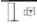
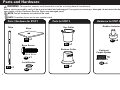
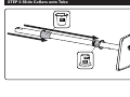
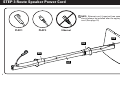
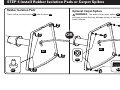
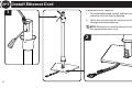
WSS1 / WSS2
SPEAKER STAND INSTRUCTION MANUAL
We’ll Make It Stress-Free
If you have any questions along the way, just give us a call.
1-800-359-5520. We’re ready to help!
IMPORTANT SAFETY INSTRUCTIONS – SAVE THESE INSTRUCTIONS – PLEASE READ ENTIRE MANUAL PRIOR TO USE
Before getting started, let’s make sure this product is perfect for you!
1
Do you own a Sonos® PLAY:1™ or PLAY:3™ speaker?
The speaker stands are designed to support only PLAY:1 and PLAY:3 speakers.
Weight Limit: 5.8 lb (2.6 kg)
2
Do you have the tool that is needed?
3
Ready to begin?
Check your speaker owner’s manual to see if there are any special requirements for mounting your speaker.
Please read through these instructions completely to be sure you’re comfortable with this easy install process.
Do not use this product for any purpose not explicitly specified by manufacturer.
Manufacturer is not responsible for damage or injury caused by incorrect assembly or use.
If you do not understand these instructions or have doubts about the safety of the installation, assembly or use of this product, contact
Customer Service at 1-800-359-5520 (UK: 0800-056-2853).
2
Dimensions
1313in.
(322
322mm)
34
34 in.
(866
866 mm)
1010in.
254mm)
(254
Top View
Front View
3
Parts and Hardware
WARNING: This product contains small items that could be a choking hazard if swallowed.
Before starting assembly, verify all parts are included and undamaged. If any parts are missing or damaged, do not return the damaged item to
your dealer; contact Customer Service. Never use damaged parts!
NOTE: Not all hardware included will be used.
NOTE: Quantities shown are for one speaker stand.
Parts / Hardware for STEP 1
Tube
Base
Parts for STEP 2
Top Collar
Hardware for STEP 4
Rubber Isolation Pads
02 x1
Base Screw
07 x4
05 x1
Bottom Collar
1/4-20 x 3/4 in.
03 x1
M6 x 20 mm
Lock Washer
04 x1
4
08 x4
06 x1
01 x1
Optional
Carpet Spikes
Spike Nuts
M6
09 x4
Parts and Hardware for STEP 5
Bracket Screw
Hardware for
STEP 6
®
Sonos PLAY:1™ Bracket
1/4-20 x 5/8 in.
Sonos® PLAY:3™
Horizontal Bracket
13 x1
2.7 in. Felt Pad
10 x1
Speaker Screw
Sonos® PLAY:3™
Vertical Bracket
1/4-20 x 3/8 in.
11 x1
15 x1
12 x1
14 x1
5
STEP 1 Install Base onto Tube
02
04
01
1/4-20 x 3/4 in.
03
6
STEP 2 Slide Collars onto Tube
05
06
7
STEP 3 Route Speaker Power Cord
NOTE: Ethernet cord, if required (see speaker manual),
should always be installed after the appropriate power
cord. (See page 10)
PLAY:1
PLAY:3
Ethernet
02
06
05
01
8
STEP 4 Install Rubber Isolation Pads or Carpet Spikes
Rubber Isolation Pads
Optional Carpet Spikes
Twist rubber isolation pads 07 into the base 02 .
WARNING: The ends of the carpet spikes 08 are sharp
and may scratch flooring, damage wiring, or be hazardous to
small children.
OR
02
02
M6
09
M6 x 20 mm
07
08
9
OPT Install Ethernet Cord
1
If ethernet cord is required:
1.
Set assembled stand upright and feed one end of
ethernet cord into the top opening.
2.
Work the cord through the tube and pull the end
through the bottom opening.
NOTE: Ethernet cord should always be installed after
the appropriate power cord.
2
10
STEP 5 Attach Speaker Bracket
10
14
1/4-20 x 5/8 in.
13
PLAY:1
11
14
PLAY:3 Horizontal
11
12
PLAY:3 Vertical
11
STEP 6 Attach Speaker - PLAY:1
1/4-20 x 3/8 in.
15
OPT
10
OPT
12
10
STEP 6 Attach Speaker - PLAY:3
Horizontal
1/4-20 x 3/8 in.
15
Vertical
1/4-20 x 3/8 in.
15
11
OPT
12
OPT
13
STEP 7 Pull Wires
14
STEP 8 Position Collars
o
D
ne!
l
l
A
15
ESPAÑOL
INSTRUCCIONES IMPORTANTES DE SEGURIDAD: GUARDE ESTAS INSTRUCCIONES Y LEA TODO EL MANUAL ANTES DE UTILIZAR ESTE PRODUCTO.
Antes de comenzar, verifiquemos que este producto sea el ideal para sus necesidades.
1
¿Posee unos altavoces Sonos® PLAY:1™ o PLAY:3™?
Los soportes para altavoces fueron concebidos para sostener altavoces PLAY:1 y PLAY:3, exclusivamente.
Peso máximo: 2,6 kg (5,8 lb)
2
¿Tiene la herramienta necesaria?
3
¿Listo para comenzar?
Consulte el manual del usuario de su altavoz para ver si existe algún requisito especial para instalar su altavoz
en la pared.
Lea estas instrucciones en su totalidad para sentirse seguro y cómodo con este fácil proceso de instalación.
No utilice este producto para ningún otro propósito que no sea el explícitamente especificado por el fabricante.
El fabricante no se responsabiliza por ningún daño o lesión resultante del montaje incorrecto o del uso indebido.
Si no entiende las instrucciones o si tiene dudas acerca de la seguridad de la instalación, del ensamblado o del uso del producto,
póngase en contacto con el servicio de atención al cliente al 1-800-359-5520 (Reino Unido: 0800-056-2853).
16
ESPAÑOL
Dimensiones (consulte la página 3)
Piezas y elementos de sujeción (consulte la página 4)
ADVERTENCIA: Este producto contiene piezas pequeñas que, si fuesen tragadas, podrían producir asfixia.
Antes de iniciar el ensamblaje, compruebe que todas las piezas estén incluidas y en buenas condiciones. Si faltan piezas o alguna está dañada, no devuelva el artículo al distribuidor. Póngase
en contacto con el servicio de atención al cliente. Nunca utilice piezas deterioradas. NOTA: No todos los elementos de sujeción incluidos deberán utilizarse. NOTA: Las cantidades que se
muestran corresponden a un soporte para altavoces.
PASO 1 Instalar la base en el tubo (consulte la página 6)
PASO 2 Instalar los collarines en el tubo (consulte la página 7)
PASO 3 Pasar el cable de alimentación de los altavoces (consulte la página 8)
NOTA: El cable Ethernet, si se requiere (consulte el manual de altavoces), debe instalarse siempre después del cable de alimentación correspondiente. (consulte la página 10)
PASO 4 Instalar las almohadillas de aislamiento de goma o las puntas para alfombras (consulte la página 9)
ALMOHADILLAS DE AISLAMIENTO DE GOMA - Gire las almohadillas de aislamiento de goma 07 hacia la base 02 .
PUNTAS OPCIONALES PARA ALFOMBRAS -
PRECAUCIÓN: Los extremos de las puntas para alfombras 08 son puntiagudos y podrían rayar el suelo, dañar el cableado o ser
peligrosos para los niños.
OPC
Instalar el cable Ethernet (consulte la página 10)
Si se requiere cable Ethernet:
1.
Coloque el soporte montado en posición vertical y pase un extremo del cable Ethernet por la abertura superior.
2.
Siga pasando el cable por el tubo y tire del extremo a través de la abertura inferior.
NOTA: El cable Ethernet debe instalarse siempre después del cable de alimentación correspondiente.
PASO 5 Ajustar el soporte del altavoz (consulte la página 11)
PASO 6 Ajustar el altavoz (consulte la página 12)
PASO 7 Jalar los cables (consulte la página 14)
PASO 8 Colocar los collarines (consulte la página 14)
17
18
19
Thank you for choosing Sanus! Please take a moment to let us know how we did:
Call us: 1-800-359-5520
Email us: [email protected]
Leave a review: sanus.com
UK: 0800 056 2853
Milestone AV Technologies and its affiliated corporations and subsidiaries (collectively, “Milestone”), intend to make this manual accurate and complete. However,
Milestone makes no claim that the information contained herein covers all details, conditions, or variations. Nor does it provide for every possible contingency in
connection with the installation or use of this product. The information contained in this document is subject to change without notice or obligation of any kind.
Milestone makes no representation of warranty, expressed or implied, regarding the information contained herein. Milestone assumes no responsibility for accuracy,
completeness or sufficiency of the information contained in this document.
©2014 Milestone AV Technologies. All rights reserved. Sanus is a division of Milestone.
All other brand names or marks are used for identification purposes and are trademarks of their respective owners.
SANUS • 6436 City West Parkway • Eden Prairie, MN 55344 USA
6901-002391 00