1
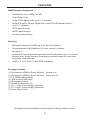
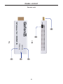
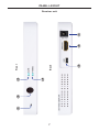
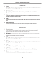
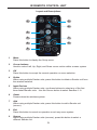
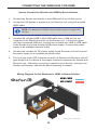
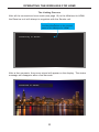
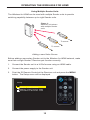
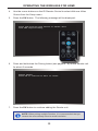
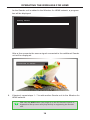
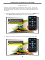
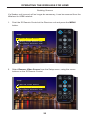
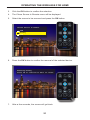
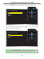
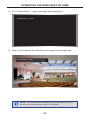
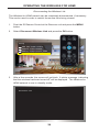
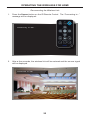
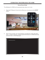
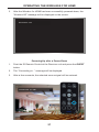
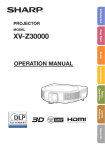
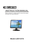
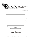
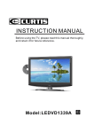
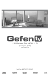
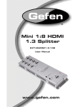
®
1080P
Wireless for HDMI
In-Room Solution
GTV-WHD-1080P-SR
User Manual
gefentv.com
ASKING FOR ASSISTANCE
Technical Support:
Telephone
(818) 772-9100
(800) 545-6900
Fax(818) 772-9120
Technical Support Hours:
8:00 AM to 5:00 PM Monday through Friday, Pacific Time
Write To:
Gefen LLC
c/o Customer Service
20600 Nordhoff St
Chatsworth, CA 91311
www.gefentv.com
[email protected]
Notice
Gefen LLC reserves the right to make changes in the hardware, packaging and
any accompanying documentation without prior written notice.
Wireless for HDMI In-Room Solution
is a trademark of Gefen LLC
© 2014 Gefen, LLC. All rights reserved.
All trademarks are the property of their respective owners.
Rev A5
CONTENTS
1Introduction
2
FCC Statement
3
Operation Notes
5Features
6
Panel Layout
6
Sender Unit
7
Receiver Unit
8
Panel Descriptions
8
Sender Unit
8
Receiver Unit
9
IR Remote Control Unit
9
Layout and Descriptions
10 Connecting the Wireless for HDMI
10
Wiring Diagram
11 Operating the Wireless for HDMI
11
The Linking Process
12
Using Multiple Sender Units
12
Adding a New Video Source
15
Renaming Sources
18
Switching between Sources
20
Deleting Sources
24
Disconnecting the Wireless Link
25
Reconnecting the Wireless Link
26
Power-Down Mode
27
Powering-Up after a Power-Down
28 Specifications
29Warranty
INTRODUCTION
Congratulations on your purchase of the GefenTV Wireless for HDMI. Your complete satisfaction is very important to us.
About Gefen
We specialize in total integration for your home theater, while also focusing on going above
and beyond customer expectations to ensure you get the most from your hardware. We
invite you to explore our distinct product line. Please visit http://www.gefen.com for the
latest offerings in High-Definition signal solutions or call us between the hours of 8:00 am
and 5:00 pm Monday-Friday, Pacific Standard Time for assistance with your A/V needs.
We’ll be happy to assist you.
The GefenTV Wireless for HDMI In-Room Solution
The GefenTV Wireless for HDMI In-Room Solution sends high definition audio and video to
any HDTV display up to 80 feet (25 meters). It extends HDMI A/V content from computers
using HDMI, set-top boxes, Blu-ray players, and other A/V sources to remote HDMIcompliant display(s). This wireless product is comprised of a small Sender unit and one
table-top Receiver unit. It supports HD resolutions up to 1080p Full HD along with support
for up to 7.1 channels of LPCM, and up to 5.1 channels of Dolby® TrueHD, and DTS-HD
Master Audio™. The Wireless for HDMI In-Room Solution transmits within the room and
does not require line-of-sight placement of transceivers for good reception. Thanks to its
small form-factor and easy to plug in Sender unit, this product is ideal for high-definition
A/V extension within a conference room or home theater installation that requires the quick
addition of portable devices such as a presentation laptop computer or a video camera to
an existing A/V system. Additional features allow multiple Sender units where each display
can access up to eight sources, using the included handheld remote control.
How It Works
Plug the Sender unit directly into the HDMI output of the source. Connect the included
HDMI cable from the Receiver unit to the HDTV display. When using a PC as the source,
connect the supplied USB-to-mini-USB cable from the PC to the Sender unit. When using
sources that do not have an available powered USB port, you will need to use the
provided USB power supply. Connect the other power supply to the DC jack on the back
of the Receiver unit. Connect the power supplies to available electrical outlets. Power-up
the source and the display. Within approximately one minute, the “Video” indicators on both
units should now glow solid blue to indicate a successful connection between the Sender
and Receiver unit. If the Sender and Receiver units do not pair automatically, the LEDs
on the Sender will continue to blink. Navigate through the on-screen menu and have the
Receiver unit look for a Sender unit. If the remote is not available, you can press and hold
the recessed pairing button on the Receiver with a paper clip until its Link LED stops blinking and goes dark. Press and hold the pairing button on the Sender unit until the Link LED
stops blinking and goes dark. If navigating the menu using the remote, press the OK button
on the IR remote. A message indicating that the Sender and the Receiver units have been
paired will appear on the display.
1
FCC STATEMENT
This device complies with part 15 of the FCC
Rules. Operation is subject to the following
two conditions: (1) This device may not cause
harmful interference, and (2) this device must
accept any interference received, including
interference that may cause undesired
operation
INSTRUCTION TO THE USER
This equipment has been tested and found to comply with the limits for a class
B digital device, pursuant to part 15 of the FCC Rules. These limits are designed
to provide reasonable protection against harmful interference in a residential
installation. This equipment generates, uses and can radiate radio frequency
energy and if not installed and used in accordance with the instructions, may
cause harmful interference to radio communications. However, there is no
guarantee that interference will not occur in a particular installation. If this
equipment does cause harmful interference to radio or television reception, which
can be determined by turning the equipment off and on, the user is encouraged
to try to correct the interference by one or more of the following measures:
•
Reorient or relocate the receiving antenna
•
Increase the separation between the equipment and Receiver unit
•
Connect the equipment into an outlet on a circuit different from that to which
the Receiver unit is connected
•
Consult the dealer or an experienced radio/TV technician for help.
In order to maintain compliance with FCC regulations, shielded cables must be
used with this equipment. Operation with non-approved equipment or unshielded
cables is likely to result in interference to radio and TV reception. The user is
cautioned that changes and modifications made to the equipment without the
approval of the manufacturer could void the user’s authority to operate this
equipment.
2
OPERATION NOTES
READ THESE NOTES BEFORE INSTALLING OR OPERATING
THE GEFENTV WIRELESS FOR HDMI - IN-ROOM SOLUTION
•
Maximum extension distance is 80 feet (25 meters) with a clear line-of-sight.
•
Supported resolutions:
»»
1080p60, 1080p50, 1080p24, 1080i60, 1080i50, 720p60, 720p50,
576p50, 576i50, 480p60, 480i60
»»
VESA: 1600x1200, 1366x768, 1280x1024, 1024x768, 800x600,
640x480)
•
Obstructions such as walls and furniture may reduce performance and
reception distance.
•
DVI-D Support
•
Gefen recommends placing both units into the provided stands, with
the Gefen logo pointing down, to help maintain the strongest possible
transmission signal.
•
Interference caused by other RF products may reduce performance and
reception distance.
•
Use with multiple Sender units:
»»
Can be used with a single Receiver unit to provide source-switching
capability.
»»
Up to 8 Senders are supported. Local RF interference can limit the
number of Sender units that can be used. Each Sender unit needs
to be placed at least 1 meter apart for optimum performance.
»»
US Models: Up to 4 pairs of Sender and Receiver units can be
operated in the same environment. Local RF interference can limit
the number of units that can be used. Each Sender unit needs to be
placed at least 1 meter apart for optimum performance. If additional
Sender / Receiver pairs are to be used, each set of units must be placed
beyond the reception range (80 feet / 25 meters) of the other in order to
prevent interference.
Continued on next page
3
OPERATION NOTES
Continued from previous page
»»
•
•
EU Models: Up to 2 pairs of Sender and Receiver units can be
operated in the same environment. Local RF interference can limit
the number of units that can be used. Each Sender unit needs to be
placed at least 1 meter apart for optimum performance. If additional
Sender / Receiver pairs are to be used, each set of units must be
placed beyond the reception range (80 feet / 25 meters) of each
other in order to prevent interference.
IR back-channel compatibility:
»»
Only products with 38 kHz IR carrier frequency are compatible. If in
doubt, please check with the equipment manufacturer.
»»
Due to complexity in some manufacturers’ IR codes, not all 38kHz
IR devices may be compatible with the IR Back Channel of the
Wireless for HDMI. The following brands have been tested by
Gefen: Panasonic, Sony, and Samsung.
Operational Limitations:
»»
Regarding US and EU models, note that all RF devices are designed
by compliance regulation to accept interference from all other
devices. Operation of wireless products is therefore dependent on the
environment they are in. Other RF products, even ones that seemingly
might not be in the frequency range, do create harmonics and other
artifacts that could interfere with the operation of the Wireless for HDMI.
4
FEATURES
HDMI Features Supported
•
Resolutions up to 1080p Full HD
•
12-bit Deep Color
•
Linear PCM digital audio up to 7.1 channels
•
Dolby® TrueHD, Dolby® Digital Plus, and DTS-HD Master Audio™
up to 5.1 channels
•
3DTV pass-through
•
HDCP pass-through
•
Lip Sync pass-through
Features
•
Wireless extension of HDMI up to 80 feet (25 meters)
•
Uncompressed High-Definition A/V from source to display
•
No latency
•
Included IR remote allows sequential switching between up to 8 sources/
Sender units. It also features three direct access buttons for your most
frequently used sources.
•
WHDI 1.0, FCC Part 15, and ETSI-compliant
Package Includes
(1) Wireless for HDMI In-Room Solution - Sender unit
(1) Wireless for HDMI In-Room Solution - Receiver unit
(1) 5 ft. HDMI cables (M-M)
(1) USB to Mini-USB cable
(1) IR Remote Control
(1) Cradle for Receiver unit
(1) 5V / 1A DC Power Supply (Sender)
(1) 5V / 2A DC Power Suppy (Receiver)
(1) Quick Start Guide
All features and specifications are subject to change without notice.
5
PANEL LAYOUT
Sender unit
5
Top
Side
4
1
2
3
6
PANEL LAYOUT
7
5
Back
4
1
2
3
Front
6
7
Receiver unit
PANEL DESCRIPTIONS
Sender Unit
1Video
This LED indicator will glow bright blue once a video link is established between
the Sender unit and the Receiver unit.
2
Pairing button
Press and hold this button for 3 seconds to pair the Sender unit with the
Receiver unit.
3Link
This LED indicator will glow bright blue once a link is established between the
Sender unit and the Receiver unit.
4USB
Connect the included USB to Mini-USB cable from the computer to this Mini-B
port.
5
1
2
HDMI Connector
Connect the Sender unit to a Hi-Def source using this HDMI connector.
Receiver Unit
Pairing button
Press and hold this recessed button using a paper clip for approximately 3
seconds to pair the Sender unit with the Receiver unit.
IR Sensor
Receives IR commands from the included IR Remote Control unit and the IR
remote of the source unit to be controlled.
3Link
This LED indicator will glow bright blue once a link is established between the
Receiver unit and the Sender unit.
4Video
This LED indicator will glow bright blue once a video link is established between
the Receiver unit and the Sender unit.
5USB
Mini-USB service port (for factory use only).
6
HDMI Out
Connect the included HDMI cable from this connector to an HD display.
7Power
Connect the included 5V DC power supply to this receptacle.
8
IR REMOTE CONTROL UNIT
Layout and Descriptions
1
9
8
2
3
7
4
6
5
1Menu
Press this button to display the Setup menu.
2
Cursor buttons
Used to control Left, Up, Right, and Down cursor motion within a menu system.
3OK
Press this button to accept the current operation or menu selection.
4Delete
When using multiple Sender units, press this button to delete a Sender unit from
the wireless network.
5
Input Devices
When using multiple Sender units, use these buttons to select any of the first
three linked Sender units. Use the Source button to select Senders 4 - 8.
6Guest
Powers down the wireless system.
7Add
When using multiple Sender units, press this button to add a Sender unit
(source).
8Exit
Press this button to cancel an operation or exit any menu system.
9Source
When using multiple Sender units (sources), press this button to select a
different Sender unit.
9
CONNECTING THE WIRELESS FOR HDMI
How to Connect the Wireless for HDMI In-Room Solution
1. Connect the Sender unit directly to the HDMI port of the Hi-Def source.
2. Connect an HD display or projector to the Receiver unit using the included
HDMI cable
NOTE: The Wireless for HDMI In-Room Solution does not support DVI
devices.
3. Connect the included USB to Mini-USB cable from a USB port on the
computer to the Mini-B connector on the Sender unit. If the source does
not have a powered USB port, connect the included mini-USB to USB cable
to the Sender and to the included USB power supply. Connect this power
supply to an available electrical outlet.
4. Connect the included 5V DC power supply to the Receiver unit and connect
the power supply to an available electrical outlet.
5. The Link and Video LED indicators on both the Sender and Receiver unit will
glow bright blue to indicate a successful connection between the Sender and
Receiver unit. Ordinarily, no pairing is required out of the box. However, the
Sender and Receiver can also be paired manually if needed.
Wiring Diagram for the Wireless for HDMI In-Room Solution
HDMI CABLE
USB POWER
®
GTV-WHD-1080P-SR
10
OPERATING THE WIRELESS FOR HDMI
The Linking Process
After all the connections have made (see page 10) to the Wireless for HDMI,
the Receiver unit will attempt to negotiate with the Sender unit.
Status Message
Provides information on the current
status of the Wireless for HDMI
Connecting to Sender...
After a few moments, the source signal will appear on the display. The status
message will disappear after a few seconds.
Connected to Sender
11
OPERATING THE WIRELESS FOR HDMI
Using Multiple Sender Units
S
I
M
S
I
V
I
W
ir
e
le
s
s
fo
r
H
D
V
S
To source
M
k
in
o
L
e
id
W
ir
e
le
s
s
fo
r
H
D
M
k
in
o
L
e
id
W
ir
e
le
s
s
fo
r
H
D
k
in
o
L
e
id
V
Video
Figure 1:
Receiver unit shown
with multiple Sender
units
Link
Wireless for HDMI R
The Wireless for HDMI can be used with multiple Sender units to provide
switching capability between up to eight Sender units.
To source
Adding a new Video Source
Before adding a secondary Sender unit to the Wireless for HDMI network, make
sure that a single Sender / Receiver pair function correctly.
1. Connect the Sender unit to a Hi-Def source using an HDMI cable.
2. Connect the power supply to the Sender unit.
3. Point the IR Remote Control at the Receiver unit and press the MENU
button. The Setup menu will be displayed.
Setup
Add new Video Source
Remove Video Source
Modify Video Source Name
Disconnect Wireless Link
12
OPERATING THE WIRELESS FOR HDMI
4. Use the cursor buttons on the IR Remote Control to select Add new Video
Source from the Setup menu.
5. Press the OK button. The following message will be displayed:
Press and hold the Link button on Sender until
Link LED stops blinking
6. Press and hold down the Pairing button (see pages 6 - 8) on the Sender unit
for about 5 seconds.
Adding Sender
Press OK to continue or Exit to cancel
7. Press the OK button to continue adding the Sender unit.
NOTE: When pairing multiple Senders, it is recommended that you
rename the ones already linked to avoid confusion.
13
OPERATING THE WIRELESS FOR HDMI
As the Sender unit is added to the Wireless for HDMI network, a progress
bar will be displayed:
Adding Sender
After a few moments the source signal connected to the additional Sender
unit will be displayed:
Connected to Sender
8. If desired, repeat steps 1 - 7 to add another Sender unit to the Wireless for
HDMI network.
TIP: Use the ADD button (see page 9) on the IR Remote Control to
bypass the Setup menu and jump directly to registering the Sender
unit.
14
OPERATING THE WIRELESS FOR HDMI
Renaming Sources
By default, each Sender unit is assigned the name “Sender”. This can be
confusing when multiple Sender unit are used. However, this identifier can
be changed to reflect, for example, the source to which each Sender unit is
connected.
1. Point the IR Remote Control at the Receiver unit, press the MENU button,
select Modify Video Source Name, then press the OK button.
Setup
Add new Video Source
Remove Video Source
Modify Video Source Name
Disconnect Wireless Link
2. Select the source to rename from the menu by using the cursor keys:
Choose Source to Rename
Sender
Sender
15
OPERATING THE WIRELESS FOR HDMI
3. The Rename Video Source Name menu will be displayed, along with the
selected Source.
Use the ▲ and ▼ cursor keys to change the highlighted character.
The ▲ key moves forward within the list of available characters and the
▼ key moves backward through the list. The list of available characters
is listed in the table below. The first character (first row, first column) is a
space and can be used anywhere in the name. The maximum length of
the Source name cannot exceed nine characters, including any spaces.
Figure 2:
Available characters for source naming
0
1
2
3
4
5
6
7
8
9
a
b
c
d
e
f
g
h
i
j
k
l
m
n
o
p
q
r
s
t
u
v
w
x
y
z
A
B
C
D
E
F
G
H
I
J
K
L
M
N
O
P
Q
R
S
T
U
V
W
X
Y
Z
Rename Video Source Name
Sender
Use the ◄ and ► cursor keys to select the character in the name to be
changed.
16
OPERATING THE WIRELESS FOR HDMI
4. After the video source has been renamed, press the OK button to save the
changes.
Select Video Source
Sender
BluRay
Setup
17
OPERATING THE WIRELESS FOR HDMI
Switching between Sources
Once two or more Sender units have been connected to a Receiver unit, use the
IR Remote Control unit to switch between each source.
1. Point the IR Remote Control at the Receiver unit and press the Source
button. The Select Video Source menu will be displayed.
Select Video Source
STB
BluRay
Setup
2. Use the Cursor buttons on the IR Remote Control to select the desired
source.
Select Video Source
STB
BluRay
Setup
18
OPERATING THE WIRELESS FOR HDMI
3. Once the desired source has been selected, press the OK button.
Select Video Source
STB
BluRay
Setup
4. The screen will go blank momentarily and the “Connecting to....” status
message will be displayed, indicating that the Receiver unit is switching to
the selected Sender unit (source).
5. After a few moments, the selected source signal will be displayed.
Connected to Sender
TIP: Use the INPUT DEVICES buttons (see page 9) on the IR
Remote Control to bypass the Select Video Source menu and
directly switch to another Sender unit.
19
OPERATING THE WIRELESS FOR HDMI
Deleting Sources
If a Sender unit (source) will no longer be necessary, it can be removed from the
Wireless for HDMI network.
1. Point the IR Remote Control at the Receiver unit and press the MENU
button.
Setup
Add new Video Source
Remove Video Source
Modify Video Source Name
Disconnect Wireless Link
2. Select Remove Video Source from the Setup menu, using the cursor
buttons on the IR Remote Control.
Setup
Add new Video Source
Remove Video Source
Modify Video Source Name
Disconnect Wireless Link
20
OPERATING THE WIRELESS FOR HDMI
3. Click the OK button to confirm the selection.
4. The Chose Source to Remote menu will be displayed.
5. Select the source to be removed and press the OK button.
Choose Source to Remove
STB
BluRay
DVR
6. Press the OK button to confirm the removal of the selected device.
Removing BluRay
Press OK to continue or Exit to cancel
7. After a few seconds, the screen will go blank.
21
OPERATING THE WIRELESS FOR HDMI
8. Press the SOURCE button to display the Select Video Source menu.
Select Video Source
STB
DVR
Setup
9. Select the desired source using the cursor buttons. Then, press the OK
button to confirm the selection.
Select Video Source
STB
DVR
Setup
TIP: Use the DELETE button on the IR Remote Control to jump
directly to the Select Video Source menu, when deleting sources.
22
OPERATING THE WIRELESS FOR HDMI
10. The “Connecting to...” status message will be displayed:
Connecting to DVR...
11. After a few moments, the selected source signal will be displayed.
Connected to DVR
NOTE: The video source will always need to be selected, even if
the source currently being viewed is not deleted.
23
OPERATING THE WIRELESS FOR HDMI
Disconnecting the Wireless Link
The Wireless for HDMI network can be completely disconnected, if necessary.
This can be used in order to restrict the source from being viewed.
1. Point the IR Remote Control at the Receiver unit and press the MENU
button.
2. Select Disconnect Wireless Link and press the OK button.
Setup
Add new Video Source
Remove Video Source
Modify Video Source Name
Disconnect Wireless Link
3. After a few seconds, the screen will go blank. A status message, indicating
that the wireless has been turned off, will be displayed. The Wireless for
HDMI network is now in standby mode.
Wireless Off
24
OPERATING THE WIRELESS FOR HDMI
Reconnecting the Wireless Link
1. Press the Source button on the IR Remote Control. The “Connecting to...”
message will be displayed:
Connecting to DVR...
2. After a few seconds, the wireless link will be restored and the source signal
will be displayed.
Connected to DVR
25
OPERATING THE WIRELESS FOR HDMI
Power-Down Mode
The Wireless for HDMI can be powered-down when not in use.
1. Point the IR Remote Control at the Receiver unit and press the GUEST
button.
2. After a few seconds, the screen Receiver and Sender unit(s) will powerdown. A status message, indicating that the Wireless for HDMI has been
powered-down, will be displayed.
Powering Down...
26
OPERATING THE WIRELESS FOR HDMI
3. After the Wireless for HDMI has been successfully powered-down, the
“Wireless Off” message will be displayed on the screen.
Wireless Off
Powering-Up after a Power-Down
1. Point the IR Remote Control at the Receiver unit and press the GUEST
button.
2. The “Connecting to...” message will be displayed.
3. After a few moments, the selected source signal will be restored.
Connected to DVR
27
SPECIFICATIONS
Operating Frequency.................................................................................... 5 GHz
Supported resolutions...................................................................... 480p to 1080p
Video Input Connector (Sender)............................. (1) HDMI Type A, 19-pin, male
Video Output Connector (Receiver)..................... (1) HDMI Type A, 19-pin,female
USB Connector (Sender / Receiver)......... (1) Mini-B (Receiver - factory use only)
Power Supply (Sender)..............................................(1) 5V / 1A DC with USB jack
(can also use powered USB port)
Power Supply (Receiver)................................................................. (1) 5V / 2A DC
Power Consumption (Sender / Receiver)........................... 3W (max.) / 8W (max.)
Dimensions (W x H x D) (Sender)................................................. 1.2” x 0.6” x 3.9”
(29mm x 14.5mm x 98mm)
Dimensions (W x H x D) (Receiver)............................................ 5.83” x 0.8” x 3.8”
(148mm x 20mm x 96mm)
Shipping Weight............................................................................. 2.0 lbs. (0.9 kg)
All features and specifications are subject to change without notice.
28
WARRANTY
Gefen warrants the equipment it manufactures to be free from defects in material
and workmanship.
If equipment fails because of such defects and Gefen is notified within two (2)
years from the date of shipment, Gefen will, at its option, repair or replace the
equipment, provided that the equipment has not been subjected to mechanical,
electrical, or other abuse or modifications. Equipment that fails under conditions
other than those covered will be repaired at the current price of parts and labor in
effect at the time of repair. Such repairs are warranted for ninety (90) days from
the day of reshipment to the Buyer.
This warranty is in lieu of all other warranties expressed or implied, including
without limitation, any implied warranty or merchantability or fitness for any
particular purpose, all of which are expressly disclaimed.
1. Proof of sale may be required in order to claim warranty.
2. Customers outside the US are responsible for shipping charges to and from
Gefen.
3. Copper cables are limited to a 30 day warranty and cables must be in their
original condition.
The information in this manual has been carefully checked and is believed to
be accurate. However, Gefen assumes no responsibility for any inaccuracies
that may be contained in this manual. In no event will Gefen be liable for
direct, indirect, special, incidental, or consequential damages resulting from
any defect or omission in this manual, even if advised of the possibility of such
damages. The technical information contained herein regarding the features and
specifications is subject to change without notice.
For the latest warranty coverage information, refer to the Warranty and Return
Policy under the Support section of the Gefen Web site at www.gefen.com.
PRODUCT REGISTRATION
Please register your product online by visiting the Register Product page
under the Support section of the Gefen Web site.
29
Rev A5
20600 Nordhoff St., Chatsworth CA 91311
1-800-545-6900
818-772-9100
www.gefentv.com
Pb
This product uses UL or CE listed power supplies.
fax: 818-772-9120
[email protected]