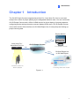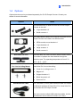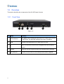
1
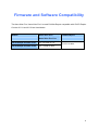
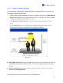
GV-3D People Counter User's Manual V1.02 Before attempting to connect or operate this product, please read these instructions carefully and save this manual for future use. 3DPCV102-A © 2013 GeoVision, Inc. All rights reserved. Under the copyright laws, this manual may not be copied, in whole or in part, without the written consent of GeoVision. Every effort has been made to ensure that the information in this manual is accurate. GeoVision, Inc. makes no expressed or implied warranty of any kind and assumes no responsibility for errors or omissions. No liability is assumed for incidental or consequential damages arising from the use of the information or products contained herein. Features and specifications are subject to change without notice. GeoVision, Inc. 9F, No. 246, Sec. 1, Neihu Rd., Neihu District, Taipei, Taiwan Tel: +886-2-8797-8377 Fax: +886-2-8797-8335 http://www.geovision.com.tw Trademarks used in this manual: GeoVision, the GeoVision logo and GV series products are trademarks of GeoVision, Inc. Windows and Windows XP are registered trademarks of Microsoft Corporation. October 2013 Contents Contents .............................................................................................................................. i Firmware and Software Compatibility............................................................................... iii Chapter 1 Introduction ..................................................................................................... 1 1.1 Features .................................................................................................................. 2 1.2 Packing List ............................................................................................................. 2 1.3 Hardware Requirements .......................................................................................... 2 1.4 Options.................................................................................................................... 3 1.5 Overview ................................................................................................................. 4 1.5.1 Front View ................................................................................................ 4 1.5.2 Rear View ................................................................................................. 5 1.6 The IR Remote Control............................................................................................ 6 Chapter 2 Getting Started................................................................................................. 8 2.1 Connecting the Device............................................................................................. 8 2.2 Restoring to Factory Default Settings ...................................................................... 9 2.3 Installing Wall Mount (Optional) ..............................................................................10 2.4 Installing VESA Monitor Mount (Optional) ...............................................................11 2.5 Installing In-Ceiling Mount (Optional) ......................................................................12 Chapter 3 The OSD Menu ................................................................................................16 3.1 Setting the Network ................................................................................................17 3.2 Setting the GV-3D People Counter .........................................................................18 3.3 Adjusting Device Time ............................................................................................19 Chapter 4 The Web Interface...........................................................................................20 4.1 Accessing the GV-Web Report Lite.........................................................................20 4.2 Setting the GV-3D People Counter .........................................................................21 4.2.1 General Settings......................................................................................22 4.2.2 People Counter Settings ..........................................................................27 4.2.3 Report to Other Servers...........................................................................28 4.3 Accessing People Counting Data............................................................................29 4.3.1 Device .....................................................................................................29 4.3.2 Group ......................................................................................................31 4.3.3 Log ..........................................................................................................33 4.3.4 Query.......................................................................................................34 Chapter 5 Content Designer............................................................................................37 5.1 Minimum System Requirements .............................................................................37 5.2 Installing the Content Designer...............................................................................38 i 5.3 Creating a Screen Layout .......................................................................................39 5.4 Exporting the Screen Layout to GV-3D People Counter..........................................41 Chapter 6 GV-IP Device Utility.........................................................................................42 6.1 Installing GV-IP Device Utility .................................................................................42 6.2 Setting the GV-3D People Counter .........................................................................43 Specifications .....................................................................................................................45 GV-3D People Counter ...................................................................................................45 Asus Xtion Pro / Asus Xtion Pro Live...............................................................................46 Appendix ............................................................................................................................47 Optimal Installation..........................................................................................................47 Detection Limitations.......................................................................................................48 ii Firmware and Software Compatibility The Asus Xtion Pro / Asus Xtion Pro Live and GV-Web Report compatible with GV-3D People Counter V1.01 and V1.02 are listed below Models Asus Xtion Pro / GV-Web Report Asus Xtion Pro Live GV-3D People Counter V1.01 V5.3.26 and V5.7.9 GV-3D People Counter V1.02 V5.7.9 and V5.8.22 V2.2.3.0 or later iii 1 Chapter 1 Introduction Introduction The GV-3D People Counter integrates Asus Xtion Pro / Asus Xtion Pro Live to count and analyze the number of people passing by the designated detection area. You can connect the GV-3D People Counter with a VGA or HDMI monitor for direct display of counting data and configuring device settings through on-screen display (OSD) menu. GV-3D People Counter comes with a built-in Web interface, the GV-Web Report Lite, for easy setup and looking up people counting data. Display Monitor I HDM Asus Xtion Pro / Asus Xtion Pro Live / VG A GV-3D People Counter Live people counts USB Inter net Infrared sensor to detect people GV-Web Report Lite or GV-Web Report Counting data and charts Figure 1-1 1 1.1 Features Counts the number of people (In and Out) Support for HDMI and VGA compatible monitors IR remote control to configure on-screen display (OSD) menu GV-Web Report Lite: Web interface to look up people counting data and charts Support for data compiling and chart analysis on GV-Web Report Audio alarm for traffic in wrong direction and exceeding maximum entries, exits or stays Content Designer to customize layout on display monitor SDHC card supported 1.2 Packing List 1. GV-3D People Counter × 1 2. IR remote control × 1 3. AC / DC adapter × 1 (12 V / 3 A, 36 W) 4. SD card x 1 5. Power cord x 1 6. Software CD x 1 1.3 Hardware Requirements In order to detect people, GV-3D People Counter must be integrated with an Asus Xtion Pro or Asus Xtion Pro Live of the following firmware versions. Asus Xtion Pro Live is available for purchase as an optional device. GV-3D People Counter V1.01: Asus Xtion Pro or Asus Xtion Pro Live V5.3.26 and V5.7.9 GV-3D People Counter V1.02: Asus Xtion Pro or Asus Xtion Pro Live V5.7.9 and V5.8.22 In addition, the Asus Xtion Pro / Asus Xtion Pro Live must be installed at a location where it will not be exposed to direct sunlight or IR LED. 2 1 1.4 Introduction Options Optional devices can be purchased separately for GV-3D People Counter. Contact your dealer for more information. Options Wall Mount Kit Detail The Wall Mount Kit is used to mount the GV-3D People Counter to the wall. VESA Monitor Mount Kit L-type brackets x 2 Small screws x 4 The VESA Monitor Mount Kit is used to mount the GV-3D People Counter to the back of a VESA monitor. Asus Xtion Pro Live VESA monitor mount bracket x 1 L-type brackets x 2 Large screws x 4 Small screws x 8 The Asus Xtion Pro Live is a motion sensor used to detect the number of people who have walked through the detection area. The operating temperature is from 0°C ~ 40°C / 40°F ~ 104°F. Asus Xtion Pro / Asus Xtion Pro Live In-Ceiling Mount USB Extension Cable The In-Ceiling Mount is used to mount Asus Xtion Pro / Asus Xtion Pro Live on the ceiling. Cover for in-ceiling mount x 1 Magnet x 2 Support bracket x 2 Black long screw x 2 Screw nut x 2 The 1.8 meters (5.9 feet) USB extension cable can extend the distance between the Asus Xtion Pro / Asus Xtion Pro Live and the GV-3D People Counter. *You can connect multiple USB extension cables, but the total distance cannot exceed 5 meters (16.4 feet). 3 1.5 Overview This section identifies the components of the GV-3D People Counter. 1.5.1 Front View 1 2 3 4 5 Figure 1-2 No. Name Function The green LED indicates the Asus Xtion Pro / Asus Xtion Pro Live 1 LED Indicators 2 USB 3 IR 4 Default Reset the GV-3D People Counter to the default factory settings. 5 SD Card Slot Connect to a SD card for local storage and firmware upgrade. 4 is connected. The red LED indicates the power is supplied. Connect to an Asus Xtion Pro / Asus Xtion Pro Live. Built-in IR receiver to receive the IR signals from the IR remote control. 1 Introduction 1.5.2 Rear View Figure 1-3 No. Name Function 1 Ethernet Connect to an Ethernet. 2 SPDIF Reserved (not functional). 3 HDMI Connect to an HDMI supported display device. 4 VGA Connect to a VGA monitor. 5 L/R Connect to a speaker. 6 Power OFF/ON Switch the power on or off. 7 DC 12V Connect to power by using the supplied power adapter. 5 1.6 The IR Remote Control Figure 1-4 No. Name Function 1 Reboot the device. 2 Reboot Number / Alphabets / Punctuation Marks Enter the numbers, alphabets or punctuation marks. 3 Back Exit the Setup Menu and return to the counting page. 4 Direction Arrows Move up, down, right and left in the Setup Menu. 5 Rec Save the settings in the Setup Menu. 6 Menu Switch to the setup menu. 7 OK Enter the setup options in the Setup Menu. 6 1 Introduction Press Shift and 0~7 to switch to one of the 8 resolutions below. 8 Shift Shift + 0 : VGA_640 x 480 Shift + 4 : HDMI_480p Shift + 1 : VGA_1024 x 768 Shift + 5 : HDMI_720p Shift + 2 : VGA_1280 x 768 Shift + 6 : HDMI_1080i Shift + 3 : VGA_1366 x 768 Shift + 7 : HDMI_1080p Note the resolution switch will cause the GV-3D People Counter to automatically reboot. 7 Chapter 2 2.1 Getting Started Connecting the Device The instructions below describe the connection required to operate GV-3D People Counter. Note: 1. For more accurate counting results, avoid placing the Asus Xtion Pro / Asus Xtion Pro Live where it can be subjected to direct sunlight or exposed to IR LED. 2. You can only connect GV-3D People Counter to one display device through HDMI or VGA connector. The video signal will be unstable if multiple display devices are connected. Figure 2-1 8 2 Getting Started 1. Connect a display device to VGA video connector or HDMI connector for video and audio alarm combined outputs. 2. Connect to a standard network cable. 3. If you use a VGA monitor, connect a speaker to L/R port for audio alarm. 4. Insert an SD card. 5. Connect the Asus Xtion Pro / Asus Xtion Pro Live to the USB port of the GV-3D People Counter. The recommended installation height for Asus Xtion Pro / Asus Xtion Pro Live is between 1.8 – 5 meters. 6. Connect to power using the supplied power adapter. 7. Switch the Power button to ON. 2.2 Restoring to Factory Default Settings If you need to restore the GV-3D People Counter to factory default settings, follow the steps below: 1. Press and hold the Default button on the front panel. Figure 2-2 2. Release the Default button when the green LED stops blinking. The GV-3D People Counter will automatically reboot after loading default. Note: The power should always be on during the process of loading default. 9 2.3 Installing Wall Mount (Optional) You can separately purchase the Wall Mount Kit to mount GV-3D People Counter on a wall. 1. Unscrew the 4 screws on the back panel of the GV-3D People Counter. Figure 2-3 2. Use the 4 screws in the package to tighten the L-type brackets on the GV-3D People Counter. L-Type Bracket L-Type Bracket Figure 2-4 10 2 Getting Started 2.4 Installing VESA Monitor Mount (Optional) You can separately purchase the VESA Monitor Mount for installing GV-3D People Counter to the back of a VESA monitor. 1. Follow steps 1 and 2 in 2.2 Installing Wall Mount to tighten the L-type brackets on the back panel of GV-3D People Counter. 2. Using the 4 large screws, tighten the VESA monitor mount bracket on the back of the computer monitor. Figure 2-5 3. Use the 4 small screws to tighten the GV-3D People Counter and the VESA monitor mount bracket together. Figure 2-6 11 2.5 Installing In-Ceiling Mount (Optional) You can separately purchase the in-ceiling mount to mount Asus Xtion Pro / Asus Xtion Pro Live on the ceiling. Before installing, note the following recommendations for in-ceiling mount: The thickness of the ceiling board should be between 0.5 – 3.0 cm / 0.2 – 1.18 in. The recommended installation height for Asus Xtion Pro / Asus Xtion Pro Live is between 1.8 – 5 meters. 1. Cut a rectangular hole in the ceiling with the measurements of 20.5 x 4.36 cm / 8.07 x 1.72 in. Figure 2-7 2. Remove the two round cover plates and unscrew the screw underneath the cover plate to remove the base. Figure 2-8 12 2 Getting Started 3. Unscrew the screws on two ends of the Asus Xtion Pro / Asus Xtion Pro Live. Figure 2-9 4. Insert the 2 black screws into the screw nuts and assemble the 2 black screws with support brackets. Figure 2-10 5. Assemble the support brackets with Asus Xtion Pro / Asus Xtion Pro Live and tighten the screws. Figure 2-11 13 6. Insert the Asus Xtion Pro / Asus Xtion Pro Live into the hole in the ceiling board. Make sure the black plastic clips are pointing vertically against the support brackets and can pass through the hole. Figure 2-12 7. After inserting, make the black plastic clips parallel with Asus Xtion Pro / Asus Xtion Pro Live. Figure 2-13 8. Tighten the screws to adjust the black plastic clips and make sure they can wedge the ceiling. Figure 2-14 14 2 Getting Started 9. Put the magnets provided in the rectangular indentations on the cover for in-ceiling mount. Figure 2-15 10. Place the cover for in-ceiling mount on Asus Xtion Pro / Asus Xtion Pro Live. Make sure the two magnets on the cover are aiming at the metal on support brackets. Figure 2-16 15 Chapter 3 The OSD Menu After connecting the devices, turn the power switch on the GV-3D People Counter to ON and the window below appears. Figure 3-1 To configure video output, network and time settings, press Menu on the remote control to enter the OSD (On-Screen Display) menu. There are three tabs in the setup menu: Network, Info and Time Setup. Note: By default, the video output is set to VGA with 1024 x 768 resolutions. If you have connected an HDMI display device, use the IR remote control to press Shift + 0~7 to switch to the corresponding resolution. 16 3 3.1 The OSD Menu Setting the Network Under the Network tab, you can configure the IP address of the GV-3D People Counter. If installed in a LAN with the DHCP server, the GV-3D People Counter will use a dynamic IP address by default. If installed in a LAN without the DHCP server, the default IP address 192.168.0.100 will be applied. Figure 3-2 1. To assign a static IP address for the GV-3D People Counter, select Static IP and enter a fixed IP address, subnet mask, DNS and gateway. 2. To use a dynamic IP assigned by the DHCP Server, select DHCP. Once connected, the current IP address will be displayed next to Connected IP. 3. Press [REC] to save the settings. The GV-3D People Counter will reboot to apply the settings. Note: You can also use the GV-IP Device Utility to set the IP address of the GV-3D People Counter. See Chapter 6 GV-IP Device Utility for details. 17 3.2 Setting the GV-3D People Counter Under the Info tab, you can set up the login ID, password, device name, video output type and resolution. You can also update the firmware of the GV-3D People Counter. Figure 3-3 User Login ID / Password: Set the ID and password to access the GV-3D People Counter. Device Name: Change the display name of the GV-3D People Counter if necessary. Output: Select VGA or HDMI according to the video output of the display monitor. Resolution: Select a screen resolution from the following options: HDMI at 60 Hz 480p 720p 1080i 1080p VGA at 60 Hz 640 x 480 1024 x 768 1280 x 768 1366 x 768 Firmware Update: Before updating firmware, copy the firmware file to the root folder of the SD card and insert the SD card to the GV-3D People Counter. Make sure there is only one firmware file in the SD card. Select Yes and press OK to begin updating firmware. The device will restart after the firmware upgrade is complete. 18 3 The OSD Menu Note: 1. By default, the video output is set to VGA with 1024 x 768 resolutions. 2. You need to allocate at least 50 MB in the device storage before upgrading the firmware. 3. You can also use the GV-IP Device Utility to rename the GV-3D People Counter and update the firmware. See Chapter 6 GV-IP Device Utility for details. 3.3 Adjusting Device Time To adjust the time of the GV-3D People Counter, select the Time Setup tab and select Adjustment. Enter the correct time and press [REC] to save. Figure 3-4 Note: If the GV-3D People Counter has been set to synchronize time with another server on the Detection Setting page of GV-Web Report Lite, you will not be able to adjust the device time on the OSD menu. For settings Time Sync, see 4.2.1 Detection Setting. 19 Chapter 4 The Web Interface After installing the GV-3D People Counter on the network, you can access GV-Web Report Lite to set up the Asus Xtion Pro / Asus Xtion Pro Live and look up counting data. The GV-Web Report Lite is a Web server built in the GV-3D People Counter. 4.1 Accessing the GV-Web Report Lite System Requirements To access GV-3D People Counter through Web browser, ensure your PC is in good network connection, and use one of the following web browsers: Mozilla Firefox V16.0.2 or later Google Chrome V.22.0.1.1229.94 or later Logging In 1. In your Web browser, type the IP address or the domain name of the GV-3D People Counter in the Location / Address field. Figure 4-1 2. Select a different Language if needed. 3. Type the ID and password. The default ID and password are admin. 4. Type the characters shown in the image and click Login. 20 4 The Web Interface 4.2 Setting the GV-3D People Counter Once you have logged in to the GV-Web Report Lite, click the Setup tab on the top to see the page below. Clicking Reset at the bottom-right corner will reset the Setup page back to default values. Figure 4-2 [Live View] Draw a line on the live view to mark the boundary of the detection zone. Subjects moving across the blue line toward the red arrow will be counted as Out. Subjects moving across the blue line toward the green arrow will be counted as In. To change the direction of the arrows, you can click the Change button after Direction Change to the right of the live view. Live View: Click to see the live image of the detection area captured by the infrared sensor of the Asus Xtion Pro / Asus Xtion Pro Live. The live image is in black and white. REC: Records the live view for 30 seconds. Only one video can be stored in the SD card at a time. The existing recording will be overwritten by the new recording. Download Recorded File: You can download the recorded file and provide the recording to service personnel for troubleshooting. 21 4.2.1 General Settings Under the live view, the following setting tabs are available: User, DDNS, SMTP, Export, SCH, IP, SD, FW, Time and MEM. [User] Machine Name: Change the display name of the GV-3D People Counter if necessary. Login Name / Password: Change the login name or password for accessing the GV-3D People Counter if necessary. The default login name and password are admin. Port: Modify the port or keep the default 30003. When connecting to other servers, GV-3D People Counter must use the same port as the servers. Output: Select VGA or HDMI according to the video output of the display monitor. Resolution: Select the screen resolution of the display monitor. Timezone: Set the time zone of the GV-3D People Counter. [DDNS] DDNS (Dynamic Domain Name System) provides a convenient way of accessing GV-3D People Counter with a dynamic IP address. DDNS assigns a domain name to the GV-3D People Counter, so that the Administrator does not need to check if the IP address assigned by DHCP Server or ISP (in xDSL connection) has changed. Figure 4-3 1. Click Register to register a GeoVision DDNS Server or apply for a Host Name from other DDNS service provider’s website. 2. Type the Host Name used to link to the GV-3D People Counter. 3. Type the Name and Password used to enable the service from the DDNS. 4. Click Connect. 22 4 The Web Interface [SMTP] You can receive a daily report of the counting results by e-mail. First, set up your mail server on this page and then go to the Export tab to enable the function. Figure 4-4 SMTP Server: Type your SMTP Server’s URL address or IP address. Port: The default port for most SMTP servers is 25. However webmail Yahoo and Hotmail generally use differently SMTP port. In this case, check your e-mail provider for the SMTP port number. Sender Email: Type the sender’s e-mail address. Login Required: If your mail server needs login authentication, select the checkbox and type your login username and password. Use SSL: Select this option if the SMTP server needs a secure connection. [Export] To automatically receive a report of the counting data everyday, select Enable Auto Export and type the Recipient E-mail. Use the Auto Export Time drop-down list to select what time to receive the report and click Apply. Make sure you set up the mail server under the SMTP tab. Figure 4-5 23 After you have completed the Export settings, you shall receive the report in a zip file at the appointed time. The report within is as the figure below. Figure 4-6 [SCH] To enable people counting only during certain time of the day, click the checkbox and specify a time period. You can set up to 3 schedules. Figure 4-7 [IP] According to your network environment, select a Network Type. DHCP: Select if your network environment has a DHCP server which can assign a dynamic IP to your device. Static IP: To set up a fixed IP address, type the IP address, subnet Mask, DNS and Gateway of the static IP. Figure 4-8 24 4 The Web Interface [SD] You can see the size of the inserted SD card, size of space used by current database and size of free space. To clear the content of the SD card, click Reset Database. Figure 4-9 [FW] You can download the latest firmware from the GeoVision’s Website at http://www.geovision.com.tw/english/5_3_3D.asp. Upload the downloaded file and click Apply. Figure 4-10 [TIME] To automatically synchronize the device time with the server time everyday, select Enable NTP Server Time SYNC. Scroll down the drop-down list to select when the device shall synchronize everyday at hourly basis. To manually set the device time, click the calendar icon to select the date and type the hour, minute and second. Click Apply. Figure 4-11 25 [MEM] By default, the counting result on the monitor is reset to zero at 12:00 midnight everyday. To set a different reset time, use the Counting value reset drop-down list to select a different time and click Apply. After you have modified the reset time, you can also click Sync DB and the monitor will now display the counting results from the new reset time. For example, if you change the reset time to 19:00 and click Sync DB, the counting results accumulated from the previous 19:00 will be displayed on the monitor. By default, the device starts counting In / Out from zero each time you restart the device. To keep the record of the In / Out value of the device, select Keep the counting (in / out) value. Click Apply and restart the device. To refresh the In / Out value manually, type the numbers in the In = and Out = fields. Click Apply and restart the device. Figure 4-12 Note: These counting settings only affect the numbers displayed on the monitor. It will not affect the counts logged into the system. 26 4 The Web Interface 4.2.2 People Counter Settings For more precise counting results, specify the height of the Asus Xtion Pro / Asus Xtion Pro Live and the minimum people height. 1. Type the height of the installed Asus Xtion Pro / Asus Xtion Pro Live in the Xtion Device Height field. Depending on how high the Asus Xtion Pro / Asus Xtion Pro Live is installed, the detectable height range for people will vary. 2. In the Minimum People Height field, type the minimum people height you want to detect. 3. Click the Detail button to see an illustration of the detectable height range and the dimension of the detection area based on the height you specified. Figure 4-13 Wrong Direction Alarm: Enable if the detection area is exit only or entrance only, and an audio alarm will sound when GV-3D People Counter detects people going in the wrong direction. Direction Change: To reverse the direction of the In and Out arrows in the Live View screen, click the Change button. After configuring People Counter Settings, click the Save button. 27 4.2.3 Report to Other Servers You can send People Counting data to up to three other GV-Web Report Lite server and / or GV-Web Report for data collection and analysis. To see how to look up data collected by the GV-Web Report Lite, refer to 4.3 Accessing People Counting Data. 1. Select Report to Server. 2. Type the IP address of the GV-Web Report Lite or GV-Web Report. 3. Modify the default Port 30003 of necessary. 4. Type the Name and the Password to access the GV-Web Report Lite or GV-Web Report. 5. If you click Time Sync under one of the servers, the time of the current GV-3D People Counter will be synchronized with the selected server. To cancel time synchronization, double-click the selected radio button. Note: 1. GV-3D People Counter is only compatible with GV-Web Report V2.2.3.0 or later. 2. Dynamic domain name is not supported in the IP field. 28 4 The Web Interface 4.3 Accessing People Counting Data After setting up the GV-3D People Counter to start collecting data, you can access the people counts, tables and charts. Use one of the following tabs in GV-Web Report Lite to look up the data. Device: Displays the counted data and graphs from all connected GV-3D People Counter. The data is updated every minute. Group: You can group the connected GV-3D People Counter and see the data of the set group. Log: Allows you to look up the data of a specified time period from the selected GV-3D People Counter. Query: Provides the daily, weekly, monthly and yearly people counting graphs and tables. 4.3.1 Device The data on the main page of the Device page is updated every minute from the GV-3D People Counter. The page displays the people counts and graphs of all connected devices. Figure 4-14 29 The tables on the main page show the following information for each GV-3D People Counter. In: The number of people entered on that day since 0:00 or since the start of schedule. Out: The number of people exited during the day. Stay: The number of people remaining. That is subtracting the number of Out from the number of In. Wrong Direction: If you have enabled the Wrong Direction Alarm in the Setup page, the number of people moving in the wrong direction during the day will be shown. The Total In, Total Out, Stay and Wrong Direction below the tables are the total number of people counted from all connected GV-3D People Counter. On the left menu, these options are available: Total List: Select a device to access its individual counts. A green mark indicates that the device is now connected to GV-Web Report Lite; otherwise a red mark appears. Counting Signage: Access the number of people counted on the day and the recent records of entries and exits. When people move in the wrong direction, the alarm will sound. The 20 more recent records will be listed at the bottom and the record will be highlighted in one of the following colors. Green (number of In detected > number of Out detected) Red (number of Out detected > number of In detected) Yellow (number of Out detected = number of In detected) Figure 4-15 30 4 The Web Interface 4.3.2 Group On the Group page, you can group the connected GV-3D People Counter, and see the people counts of the set group. You can also set up the maximum number of people entered, left and remaining to activate the computer alarm when the number is exceeded. E-mail notification can be activated when the number of people remaining reaches the pre-defined maximum. To set up a group: 1. Select Add Group from the left menu. This page appears. Figure 4-16 2. Name the group. 3. Select the GV-3D People Counter you want to include in the group. 4. In the Maximum In field, set the maximum number of people that can enter during the day before activating the computer alarm. 5. In the Maximum Out field, set the maximum number of people that can leave during the day before activating the computer alarm. 6. In the Maximum Stay field, set the maximum number of people that can remain during the day before activating the computer alarm, sending a notification e-mail or triggering an output device. 7. Click Submit. 31 8. To organize multiple groups into subgroups, click Setting Group Relations in the left menu. Drag and drop a group under another group to make it a subgroup. Figure 4-17 On the left menu of the Group page, you can find these options: Total List: Access the people counts of the set groups updated every minute. Counting Signage: Access the people counts of the set groups updated in real time. When the limit of Maximum In, Maximum Out or Maximum Stay is reached, the warning texts will be displayed on the page and the computer alarm will be activated too. 32 4 The Web Interface 4.3.3 Log On the Log page, you can look up the people counts per hour of a specified time period from the selected GV-3D People Counter or group. Figure 4-18 To search the log data: 1. Select a specific GV-3D People Counter from the Device drop-down list or a created group from the Group drop-down list. 2. Specify Start Time and End Time of the log data. 3. Click Query to display the search results. To back up the search results in EXCEL or WORD, click the icons at the bottom of the Query Result List. Under Wrong Direction, you can click [Detail] to see the time of the wrong entry or exit during that hour. Figure 4-19 33 4.3.4 Query The Query page provides you with the daily, weekly, monthly and yearly people counting graphs and tables. To search the counting data, select a GV-3D People Counter from the Device drop-down list or a created group from the Group drop-down list, specify a date, and select the options below. Use the Chart drop-down list graph, line graph or pie graph. to choose to display the data using bar To back up the search results in EXCEL or WORD, click the icons Query Result List. at the bottom of the Note: Pie graph is not available for the following types of data: In/Out Counts per hour and Total Stay Total In, Out and Stay per Hour In Counts per Hour Out Counts per Hour Total Stay per Hour [Daily Report] Display the counting report of the specified date. In/Out Counts per hour and Total Stay: The hourly number of people entered and left, and the total number of people remaining until now. Difference between In and Out per hour: The hourly number of people remaining. Total In, Out and Stay per hour: The total number of people entered, left and remaining during the day. 34 4 The Web Interface The following figure is an example of the In/Out Counts per hour and Total Stay option. The value 12, 15 indicates the count of remaining people until 12 pm is 15. Figure 4-20 [Weekly Report] Display the weekly report that contains the data of 7 days before your specified date. In Counts per hour: The hourly number of people entered for the week. Out Counts per hour: The hourly number of people left for the week. Total Stay per hour: The hourly number of people remaining for the week. In Percentage per day: The daily percentage of people entered for the week. In Percentage per hour: The hourly percentage of people entered for the week. Stay Percentage per hour: The hourly percentage of people remaining for the week. 35 The following figure is an example of the In Percentage per day option. The value 2012-12-20 (Thu), 29 (26.85%) indicates the total number of entered people on 2012/12/20 is 29. The number takes up 26.85 percent of the total people entered for the week. Figure 4-21 [Monthly Report] In Percentage per day: The daily percentage of people entered in the month. In Percentage per hour: The hourly percentage of people entered in the month. Stay Percentage per hour: The hourly percentage of people remaining in the month. [Yearly Report] In Percentage per month: The monthly percentage of people entered in the year. Out Percentage per hour: The hourly percentage of people entered in the year. Stay Percentage per hour: The hourly percentage of people remaining in the year. 36 5 Chapter 5 Content Designer Content Designer Using the Content Designer, you can customize the screen layout for display monitor to show the in counts, out counts, stay counts and the current time. 5.1 Minimum System Requirements The minimum system requirements to install and run the Content Designer: 32-bit Windows XP / 7 64-bit Windows XP / 7 OS Supported CPU Pentium 4, 3.0 GHz RAM 1 GB HDD 80 GB VGA AGP or PCI-Express, 800 x 600 (1280 x 1024 recommended), 32-bit color DirectX 9.0c .NET Framework 3.5 37 5.2 Installing the Content Designer Follow the steps below to install the Content Designer: 1. Insert the Software CD to your computer. It runs automatically and a window pops up. Figure 5-1 2. Select Install DirectX 9.0c and follow the on-screen instructions. 3. Select Install Microsoft .NET Framework 3.5 and follow the on-screen instructions. 4. Select GeoVision Content Designer and follow the on-screen instructions. 38 5 5.3 Content Designer Creating a Screen Layout 1. To create a project, click File on the menu bar and select New Scenario. 2. Select GV-3D People Counter and a screen resolution. The screen resolution must match the resolution you set for the display monitor. Figure 5-2 Note: The following resolutions for HDMI and VGA video outputs are available: HDMI at 60 Hz 480p 720p 1080i 1080p VGA at 60 Hz 640 x 480 1024 x 768 1280 x 768 1366 x 768 For HDMI 480p, select 720 x 480; for HDMI 720p, select 1280 x 720; for HDMI 1080p and 1080i, select 1920 x 1080. 3. On the top-left corner, click the Background Image icon and click Browse to select a picture in PNG, JPEG or BMP format to be the background image. Figure 5-3 39 Note: The In Count, Out Count, Stay Count and Current Time will be shown on the display monitor as numbers only. If you wish to label the counting data, you will need to add a background picture with text added where the data will be shown. For example: Figure 5-4 4. On the left side, click the In Count, Out Count, Stay Count and Current Time icons to add these objects to the main screen. Figure 5-5 5. You can adjust the size and position of the objects using the Size and Position fields in the bottom-left corner or drag and drop the object boxes. To resize the box for Current Time, double-click the object and select from a list of pre-defined resolutions. 40 5 5.4 Content Designer Exporting the Screen Layout to GV-3D People Counter 1. To preview the created screen layout, click Preview screen. on the main 2. To save the screen layout, click File and select Output Scenario. 3. Click to browse the location to save the screen layout. The screen layout will be saved in a folder named 3DPeopleCounter. Figure 5-6 4. In a SD card, create a folder named Scenario and copy the 3DPeopleCounter folder to the Scenario folder. 5. Turn off the GV-3D People Counter, insert the SD card, and restart the GV-3D People Counter to apply the new screen layout. 41 Chapter 6 GV-IP Device Utility GV-IP Device Utility can detect GV-3D People Counter in the LAN and allows you to quickly set the IP address of the device, upgrade firmware and reboot the device. 6.1 Installing GV-IP Device Utility 1. Insert the Software CD to your computer. It runs automatically, and this window appears. Figure 6-1 2. Select Install GV-IP Device Utility, and follow the on-screen instructions. 42 6 6.2 GV-IP Device Utility Setting the GV-3D People Counter 1. To start the GV-IP Device Utility, go to Windows Start, point to Programs and select GV IP Device Utility. The window below appears and automatically searches for any GV-IP device under LAN. Figure 6-2 2. Double-click a GV-3D People Counter. This dialog box appears. Figure 6-3 43 3. Click the different tabs to access the following settings: Set IP Address: Type the IP address, subnet mask, default gateway and DNS server of the GV-3D People Counter. Firmware Upgrade: To upgrade the firmware, click Browse to specify the path of the firmware file and click Upgrade to proceed. You can select Upgrade all devices to upgrade all other GV-3D People Counter of the same username and password. 44 Device Name: Renames the GV-3D People Counter. Reboot: Reboots the GV-3D People Counter. Specifications Specifications GV-3D People Counter Video HDMI 480p, 720p, 1080i, 1080p Output VGA 640 x 480, 1024 x 768, 1280 x 768, 1366 x 768 Audio 3.5 mm Jack (for alarm) IR Remote Control Yes Local Storage SDHC card slot (4-32 G, Class 4 or above, FAT32 format) Ethernet 10/100 Ethernet Power Adapter 12V / 3A DC Jack (Max. 36 W) Supported Browser Mozilla Firefox, Google Chrome Operating Temperature 0°C ~ 40°C (32 °F ~ 104 °F) Operating Humidity 20 % ~ 80 % (with no condensation) Dimensions (W x H x D) 182.3 × 28.9 × 131 mm (7.18 × 1.14 × 5.16 in) Weight 615 g (1.36 lb) Regulatory CE, FCC compliant OSD English Web Interface English, Russian, Traditional Chinese, Simplified Chinese Language All specifications are subject to change without prior notice. 45 Asus Xtion Pro / Asus Xtion Pro Live Max. Power Consumption 2.5 W Operating Distance 0.6 – 5 m (1.97 – 16.40 in) Operating Environment Indoor Operating Temperature 0°C ~ 40°C / 40°F ~ 104°F Angle of View Interface Diagonal 70° Horizontal 58° Vertical 45° USB 2.0 All specifications are subject to change without prior notice. 46 Appendix Appendix Optimal Installation To increase the accuracy of people counting results, be sure to install the Asus Xtion Pro / Asus Xtion Pro Live with the correct lighting conditions and avoid placing IR LED nearby. The recommended installation height for Asus Xtion Pro / Asus Xtion Pro Live is between 1.8 – 5 meters. Avoid Direct Sunlight Direct sunlight on the detection area may show up as a white region on the live view and interferes with people counting results. Avoid IR LED IR LED from the left of the view interferes with the IR sensor of the Asus Xtion Pro / Asus Xtion Pro Live and causes part of the person’s head to appear dark. 47 Detection Limitations There are situations that may cause GV-3D People Counter to falsely detect the number of people. Below are examples of situations that may or may not result in false detection. Actual: 1 Counted: 1 Actual: 1 Counted: 1 Actual: 1 Counted: 1 Actual: 2 Counted: 2 Actual: 2 Counted: 1 48 Standing upright Leaning forward Squatting down Shoulder to shoulder Head leaning on shoulder Appendix Actual: 2 Counted: 1 Actual: 2 Counted: 2 Actual: 4 Counted: 4 Head to head One hand on shoulder Multiple people Carrying a large backpack: Actual: 1 Backpack in close contact with the Counted: 1 person’s head. Actual: 2 Backpack at a distance from the Counted: 3 person’s head. 49 Pushing a cart: Actual: 1 Counted: 1 Cart close to the person’s body. Cart away from the person’s body. Actual: 1 Tip: Set a minimum detection height Counted: 2 that is higher than the cart to avoid false detection. Pushing a wheelchair: Actual: 2 The person pushing the wheelchair is Counted: 2 standing upright. Actual: 2 Counted: 1 50 The person pushing the wheelchair leans over and overlaps with the wheelchair user.