1
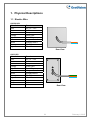
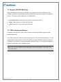
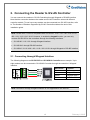
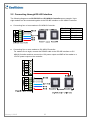
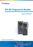
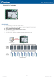
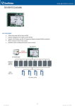
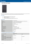
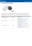
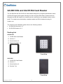
GV-RK1352 and GV-R1352 Card Reader The GV-RK1352 and GV-R1352 are card readers designed to recognize identifications cards. GV-RK1352 comes with keypad, allowing it to also recognize PIN codes. Featured with the Wiegand and RS-485 outputs, the readers can be connected to any standard access control panel. The readers are protected by a weather sealed and IP66 compliant housing for outdoor use. The content of this installation guide refers to the following readers: • GV-RK1352 firmware V1.2 • GV-R1352 firmware V1.2 Packing List GV-RK1352 1. GV-RK1352 Card Reader 2. Screw x 2 3. Screw Anchor x 2 4. Front Cover Plate x 2 Front View GV-R1352 1. GV-R1352 Card Reader 2. Screw x 3 3. Screw Anchor x 2 4. Security Torx Front View February 6, 2015 1 1. Physical Descriptions 1.1 Electric Wire GV-RK1352 Wire Color Red Black Yellow Orange Light Red Green White Blue Light Blue Function DC 7.5 ~ 12 V GND Beeper Green LED Red LED Wiegand Data 0 Wiegand Data 1 RS-485 + RS-485 - Rear View GV-R1352 Wire Color Function Red Black Yellow Orange Light Red Green White Blue Light Blue Gray Purple Brown DC 7.5 ~ 12V GND Beeper Green LED Red LED Wiegand Data 0 Wiegand Data 1 RS-485 + RS-485 N/A N/A N/A Rear View 2 February 6, 2015 1.2 Keypad (GV-RK1352 Only) When accessing an entry using GV-RK1352, you can enter the door’s PIN code on the keypad or present the card and then enter the card’s PIN code on the keypad to be granted access. The access mode is defined on GV-ASManager. 1. 0~9 Number Keys: Press the number keys to enter the PIN code. 2. # Key: Press the # key to confirm the PIN code. 3. ﹡Key: Press the ﹡key to cancel the PIN code. 1.3 LED Indicator and Beeper In standby mode, the LED is blue. When a card is read, the LED flashes green and the beeper beeps once. The reader comes with external control wires for Green LED, Red LED and Beeper. You can connect these control wires to a GV-AS Controller to change the default settings of the LED and Beeper. For details on how to configure the settings, refer to 5. Changing the Settings of Beeper and LED later in this installation guide. Note: You can only connect the LED and beeper wires to GV-AS210 / 2110 / 400 / 410 / 4110 / 810 / 8110. February 6, 2015 3 2. Connecting the Reader to GV-AS Controller You can connect the readers to GV-AS Controllers through Wiegand or RS-485 interface. Note that the connection between the reader and GV-AS Controller varies with different controller models. To see how many readers can be connected to a GV-AS Controller, refer to The Number of Readers Supported by GV-AS Controllers table at the end of this installation guide. Note: GV-RK1352 / R1352 is compatible with GV-AS100 / 1010 / 110 / 120 / 210 / 2110 / 400 / 410 / 4110 / 810 / 8110. However, to enable the keypad function, you can only connect GV-RK1352 to the controllers through the following interfaces. • GV-AS100 / 110 / 120: through Wiegand interface • GV-AS1010: through RS-485 interface • GV-AS210 / 2110 / 400 / 410 / 4110 / 810 / 8110: through Wiegand or RS-485 interface 2.1 Connecting through Wiegand Interface The following diagrams use GV-RK1352 and GV-AS810 Controller as an example. Up to eight readers can be connected to GV-AS810 Controller through the controller’s Wiegand Wiegand A interface. Wire Color Black White Green Function GND Wiegand Data 1 Wiegand Data 0 Red DC 7.5 ~ 12V Note: Connection through Wiegand interface is not supported for GV-AS1010. 4 February 6, 2015 2.2 Connecting through RS-485 Interface The following diagrams use GV-RK1352 and GV-AS810 Controller as an example. Up to eight readers can be connected together to the RS-485 interface on GV-AS810 Controller. z Connecting four or less readers to GV-AS810 Controller: Wire Color Black Light Blue Blue Red z Function GND RS-485 RS-485 + DC 7.5 ~ 12V Connecting five or more readers to GV-AS810 Controller: For readers five to eight, connect the RS-485 cable to the RS-485 interface on GVAS810 Controller and then connect the 12V power output and GND of the reader to a 12V DC power output on the controller. February 6, 2015 5 2.2.1 Defining Readers on GV-AS Controller Web Interface Since multiple readers can connect to GV-AS Controller using one RS-485 interface, you need to specify which door each reader controls. This section explains how to define readers on the Web interface of GV-AS Controller. On the Web interface, you can also set the reader to read the GID or UID on GV-AS ID Cards / Key Fobs. Note that the Web interface of different GV-AS Controller models varies. 1. On the controller’s Web interface, click Extended Reader. This dialog box appears. 2. In the GV-Reader/CR420/GF1921/GF1922 section, select the RS485 checkbox in front of the ID number and type the Serial Number on the rear panel of the reader. The ID number will be assigned to the reader. 3. Select a door/gate for the reader from the Function drop-down list. 6 February 6, 2015 4. Next to Read Mode, select Read UID or Read GID to set the connected readers to read UID (unique identifier) or GID (GeoVision ID) on GV-AS ID Cards / Key Fobs. If you select Read GID, make sure there are two numbers on your GV-AS ID Cards / Key Fobs as shown below. If there is only one number on your GV-AS ID Cards / Key Fobs, GID is not supported, and you must select Unique Identification (UID). 5. Click Submit. Note: 1. When you click Submit on the Extended Reader page of a GV-AS1010 / 210 / 2110 / 410 / 4110 / 810 / 8110, all readers connected through RS-485 interface will reboot. 2. GID ID format is only supported in GV-RK1352 / GV-R1352 V1.2 or later. 3. If you are using third-party cards or key fobs, you must set the reader to read UID. February 6, 2015 7 3. Installing the GV-R/RK/DFR Config AP The GV-R/RK/DFR Config AP allows you to set the reader’s beeper / LED, ID number, master / slave status, and whether it reads UID or GID. When using the Config AP, the reader needs to be connected to a PC through GV-COM, GV-Hub or GV-NET/IO Card V3.1. You can install the Config AP from the Software DVD or GeoVision Website. To use a GVCOM, GV-Hub or GV-NET/IO Card V3.1, you also need to install GeoVision USB Device Driver. Installing from Software CD 1. Insert the software CD and the Install Program window will pop up automatically. 2. Select Install GeoVision USB Device Driver. 3. In the GeoVision USB Driver Installer window that appears, select Install. 4. Go back to the Install Program window, and select Run GV-Reader Config Utility. Downloading from GeoVision Website 1. Go to the Software Download and Upgrading page of GeoVision Website: http://www.geovision.com.tw/english/5_8_AS.asp 2. Find the Supplemental Utilities section under the Access Control tab, and click the Download icon of GV-RK1352 & GV-R1352 & GV-DFR1352 Config Utility. 3. Under the Driver section, click the Download icon 8 of GV-USB Device Driver. February 6, 2015 4. Overlaying Card Numbers on GV-System Live View You can overlay card numbers recognized at the reader onto a camera channel on GVSystem. To overlay card numbers on GV-System channel, the reader needs to be connected to a GV-System through GV-COM, GV-Hub or GV-NET/IO Card V3.1. RS-485 (Blue) RS-232 RS-485 + USB (Light Blue) RS-485 - GV-RK1352 or GV-R1352 GV-HUB / GV-COM / GV-NET/IO Card GV-System Note: GV-RK1352 / GV-R1352 is not compatible with GV-NET Card and GV-NET/IO Card of versions earlier than V3. 4.1 Defining the ID Number and Setting the Reader to Slave After the reader is connected to the computer of the GV-System, use the GV-R/RK/DFR Config AP to define the ID number of the reader and set the reader to Slave. 1. Run GV-R/RK/DFR Config AP. Refer to 3. Installing the GV-R/RK/DFR Config AP above for how to install. February 6, 2015 9 2. Select the COM port that is connected to the reader and click Open COM. The serial number and firmware version of the reader will be automatically detected. The red square next to the COM port box should change to blue to indicate the COM port is correct. 3. Under Master / Slave, set the reader to Slave. 4. Select an ID number for the reader. The ID number ranges from 0 to 7. 5. Click Setup. The settings are sent to the reader. If you want to connect multiple readers to the GV-System, you need to set up a unique ID number for each reader. For this you need to connect each reader to the computer one reader at a time, and follow the instructions above to set up an ID number. Note: 1. If the COM port is incorrect, an “Error opening serial port” message will appear. To verify the COM port that is connected to the reader, go to Windows Device Manager. In the Ports (COM & LPT) field, you should see the entry for Prolific USB-to-Serial Comm Port and the COM number currently in use. 2. If you are using an older version of the Config AP, you will have to manually type the serial number of the reader. The serial number is on the rear panel of the reader. 10 February 6, 2015 4.2 Adding the Reader to GV-System 1. In GV-System, click the Configure button, select Accessories, and select GV Wiegand Capture Device Setting. This dialog box appears. 2. Click the New button. This dialog box appears. Type: Select GV-Wiegand Capture. Device: Type a number and name to help you identify the reader. COM: Select the COM port connected to the reader. Address: Select the ID of the connected reader you set in GV-R/RK/DFR Config AP. Camera: Assign the reader to a channel to overlay card numbers on the live view. 3. Click the Add button. February 6, 2015 11 5. Changing the Default Settings of Beeper and LED You can change the default settings of the LED and the beeper by enabling a GV-AS210 / 2110 / 400 / 410 / 4110 / 810 / 8110 to externally control the LED and Beeper. Through the Web interface, you can set the controller to trigger the red LED, green LED or beeper when the specified alarm events occur. For GV-AS400, built-in LED and beeper settings are available on the Web interface for outputs 9 ~ 16. The GV-AS Controller and the reader need to be connected through Wiegand interface. You will have to: 1. Enable external control of the reader’s Beeper and LED by using the GV-R/RK/DFR Config AP. 2. Wire the Beeper, Red LED and Green LED from the reader to the GV-AS Controller. 3. Specify the Beeper and LED settings for each door through the Web interface of GV-AS Controller. 5.1 Setting up Beeper and LED on GV-R/RK/DFR Config AP To enable the external controls of the Beeper and LED on GV-R/RK/DFR Config AP, the reader needs to be connected to a computer through GV-COM, GV-Hub or GV-NET/IO Card V3.1. 1. Start the GV-R/RK/DFR Config AP and select the COM port that is connected to the reader. Note: To see how to install the Config AP and how to identify the COM port of the reader, refer to 3. Installing GV-R/RK/DFR Config AP and 4.1 Defining the ID Number and Setting the Reader to Slave earlier in this installation guide 12 February 6, 2015 2. Click Open COM. The serial number and the firmware version of the reader will be automatically detected. 3. To enable external control of Beeper or LED, select Beeper, Green LED or Red LED. 4. Select Master from the Master / Slave drop-down list. 5. Select an ID number for the reader. Make sure the ID number on the Config AP matches the ID number set on the Extended Reader page of the GV-AS Controller Web interface. 6. Click Setup. The settings are sent to the reader. If you want to set up multiple readers to be controlled by the controller, you need to connect each reader to the computer one reader at a time, and follow the above instructions to enable external control. After the above settings, you need to connect the Beeper, Red LED and Green LED wires from the reader to the outputs of GV-AS Controller. February 6, 2015 13 5.2 Wiring the Beeper and LED to the GV-AS Controller To wire the beeper and LED to GV-AS210 / 2110 / 400 / 410 / 4110 / 810 / 8110, connect the control wires of the reader’s Beeper, Red LED or Green LED to any of the outputs on GV-AS Controller. Note that outputs 9 ~ 16 on GV-AS400 are used for the built-in LED and beeper settings. Wiring LED to GV-AS Controller The diagram below shows the connection for wiring Green LED using GV-RK1352 and GVAS810 as an example. For Red LED, use the light red wire instead. OUT12 OUT11 Wire Color Function Black Orange Light Red GND Green LED Red LED Wiring Beeper to GV-AS Controller The diagram below shows the connection for wiring the beeper using GV-RK1352 and GVAS810 as an example. OUT12 OUT11 Wire Color Black Yellow 14 Function GND Beeper February 6, 2015 After wiring, you also need to go to GV-ASManager to select the alarm conditions that will set off the reader’s beeper. In GV-ASManager, right-click the GV-AS Controller in the device list, click Settings, and click the Door / Gate tab to select the alarm conditions. February 6, 2015 15 5.3 Configuring the Beeper and LED Settings for Each Door/Gate After connecting the wires for beeper or LED, specify the conditions to trigger the beeper and LED on the GV-AS210 / 2110 / 400 / 410 / 4110 / 810 / 8110 Web interface. 1. On the controller Web interface, click Output Setting. The page below appears. 2. Find the output wired to the beeper or LED and specify up to 2 alarm conditions to set off the beeper or LED. a. Output Type: Select Normal, Toggle or Pulse. If you select Pulse, you can specify the number of seconds to trigger the beeper or LED. b. Output Conditions: Select the door and the alarm conditions to trigger the beeper or LED. Up to 2 sets of output conditions can be set. 3. If you have wired the beeper or LED to outputs 9 ~ 16 on GV-AS400, select a door and select Beeper, Green LED, Red LED or Invert Red LED. Beeper: Enables the external control of Beeper. Green LED: Changes the standby color to blue. When a card is read, the LED flashes green. RED LED: Changes the standby color to red. When a card is read, the LED flashes blue. Invert Red LED: Changes the standby color to blue. When a card is granted access, the LED flashes red. 4. Click Submit. 16 February 6, 2015 6. Setting UID or GID on GV-R/RK/DFR Config AP By default, the readers read the UID (unique identifier) on ID cards or key fobs. Using GVR/RK/DFR Config AP, you can set the GV-RK1352 / GV-R1352 to read GID (GeoVision ID) on GV-AS ID Cards / Key Fobs instead. Note: 1. To see how to install the Config AP and how to identify the COM port of the reader, refer to 3. Installing GV-R/RK/DFR Config AP and 4.1 Defining the ID Number and Setting the Reader to Slave earlier in this installation guide 2. GID ID format is only supported in GV-RK1352 / GV-R1352 V1.2 or later. 3. If you are using third-party cards or key fobs, you must set the reader to read UID. 1. Run GV-R/RK/DFR Config AP. 2. Select the COM port that is connected to the reader and click Open COM. The serial number and firmware version of the reader will be automatically detected. The red square next to the COM port box should change to blue to indicate the COM port is correct. 3. To set the reader to read GID, select Only Read GID. 4. Click Setup to apply the setting. February 6, 2015 17 To use GID, make sure there are two numbers on your GV-AS ID Cards / Key Fobs as shown below. If there is only one number on your GV-AS ID Cards / Key Fobs, GID is not supported and you must select Unique Identification (UID). 18 February 6, 2015 7. Firmware Upgrade GeoVision will periodically release the updated firmware on the website. The new firmware can be simply loaded into the reader by using Update Utility included in the Software CD. Important Notes before You Start Before you start updating the firmware, please read these important notes: 1. While the firmware is being updated, the power supply must not be interrupted. 2. Do not turn the power off within 10 minutes after the firmware is updated. WARNING: The interruption of power supply during updating causes not only update failures but also damages to the device. In this case, please contact your sales representative and send your device back to GeoVision for repair. To upgrade firmware: 1. Insert the Software CD and select Run Firmware Update Utility. This dialog box appears. 2. Select the COM port of the reader. 3. Click the Browse button to locate the firmware file (.bin) saved at your local computer. 4. Click Update. 5. The LED indicator should flash purple during the process of firmware upgrading. When the process is complete, the reader will be sounded twice and the LED indicator will change to green. Note: You can also download the firmware upgrade utility from the GeoVision website: http://www.geovision.com.tw/english/5_8_AS.asp. Under the Access Control tab, click the Download icon of GV-RK1352 & GV-R1352 & GV-DFR1352 Firmware Upgrade Utility. February 6, 2015 19 8. Specifications GV-RK1352 GV-R1352 CPU 8-bit microprocessor Frequency 13.56 MHz for ISO14443A (Mifare DESFire, Mifare Plus and Mifare Class) Wiegand Interface Wiegand 26 / 34 bits, distance 30 m / 98.43 ft RS-485 9,600 bps, connect up to 8 GV-RK1352 / R1352 units Power DC 7.5 ~ 12V LED Red, Green and Blue LED Beeper Buzzer Reader Color Black Supported ID Formats Reads GID and UID Operating Temperature -35 °C ~ 65 °C / -31 °F ~ 149 °F Operating Humidity 10% ~ 90% (no condensation) Dimensions (W x H x D) 95 x 108 x 23 mm / 3.74 x 4.25 x 0.91 in 65.80 x 115.6 x 20.5 mm / 4.6 x 2.6 x 0.8 in Weight 260 g / 0.57 lb 120 g / 0.26 lb Ingress Protection IP66 Certification CE, FCC, RoHS -30 °C ~ 65 °C / -22 °F ~ 149 °F 8.1 The Number of Readers Supported by GV-AS Controllers GV-AS Controller Model Number of GV-RK1352 / R1352 Supported Wiegand RS-485 GV-AS100 1 1 GV-AS1010 Not supported 2 GV-AS110 / 120 1 Not supported GV-AS100 / 110 / 120 with GV-ASBox 2 4 GV-AS100 / 110 / 120 with GV-ASNet Not supported 2 GV-AS210 / 2110 4 8 GV-AS400 8 8 GV-AS410 / 4110 / 810 / 8110 8 8 20 February 6, 2015 9. Accessory (GV-RK1352 Only) Optional accessories can expand the capabilities and versatilities of your GV-RK1352 Card Reader. Consult your sales representative for more information. GV-MountA900 is a mounting plate that allows you to attach GV-RK1352 to a US single gang power box. GV-MountA900 • Dimensions: 100 x 68 mm / 3.9 x 2.7 in • Weight: 55 g / 0.12 lb Connecting GV-MountA900 Screw GV-MountA900 to the US single gang power box through the hole C and to GVRK1352 through the hole B as shown below. February 6, 2015 21