1
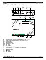
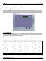
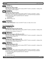
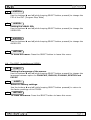
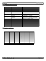
TM250 A/V to DVBT encoder/modulator USER MANUAL V1.2 1 - Safety considerations...............................................................page 3 2 - Description of the different elements..........................................page 4 3 - Installation and menu structure................................................ page 3.1 - Installation.......................................................................... page 3.2 - Powering up........................................................................ page 3.3 - Menu structure........ ........................................................... page 5 5 5 5 4 - Programming mode.. .............................................................. page 4.1 - Description of the INPUT menu...............................................page Description of the OUTPUT menu............................................ page 4.3 - Description menu EXTRA........................................................page 4.4 - Description menu MISC (misecellanous).................................. page 6 6 7 8 9 Programming using a PC.......................................................... page 10 6 - Technical specifications.............................................................page 11 7 - Factory settings.......................................................................page 11 1. - Safety considerations 1.1 CONNECTING TO THE MAINS SUPPLY This product has to be connected to the mains supply. If there is the slightest doubt concerning the type of connection available on the installation, please contact your supplier of electricity. Before carrying out maintenance operation or modification of the installation, the modulator has to be disconnected. Remark : only use the supplied power adaptor. 1.2 OVERVOLTAGE An overvoltage on hte mains supply,can cause shortcircuits are fire. Never overload the power lines. 1.3 LIQUIDS This module should be protected from splashes. Please assure yourself that no containers containing liquids is placed on this module. Also be aware of other persons splashing liquids on the module. 1.4 CLEANING Disconnect the module before cleaning. Using only a humid cloth without solvant. solvant. 1.5 VENTILATION In order to assure an adequate air circulation and to prevent overheating, the ventilation holes should not be obstructed. The module may not be installed in a hermetically sealed environment. Other electronic products or heat producing items may not be placed upon or near the module. 1.6 ACCESSORIES The use of accessories not manufactured by the manufacturer can cause damage to the module. 1.7 INSTALLATION OF THE MODULE The module must be installed in a place well protected from direct sunlight. All measures have to be taken to avoid installation in humid or sunny places.Do not install near heating elements or other devices producing heat. Assure yourself that the module is placed at least 10 cm form other equipment with is susceptible to electromagnetic radiation. Do not install the module on instable items. A fall cans cause physical or material damage. 2 - Description of the different elements DC input AUDIO VIDEO LEFT INPUT OUTPUT RIGHT TM250 A/V to DVBT encoder/modulator Power supply input of the modulator (5 VDC / 4 A) USB input( for programming the TM250 by PC) Video input Audio left input Audio right input RF input RF output LCD display 1 x 8 characters with backlight SELECT button button button 3 - Installation and menu structure 3.1 - Installation Install the TM250 against a wall using the wall fixation brackets to ensure cooling of the housing through natural convection. ( see drawing) Connect the audio and video source using CINCH connectors. Connect the RF input cable (if present) and the RF output cable. If the RF input is not used, please connect a 75 ohm terminating resistor to it. Once the modulator installed and the cables connected, please proceed connecting the power supply to the modulator. 3.2 - Powering up Plug in the connector of the power supply. The LCD display will light up and shows the message “Init...” followed by a bargraph, during starting up of the TM250. After starting up the message “TM250’ and “V1.9’ (firmware version) are displayed alternating. 3.3 - Menu structure The TM250 has different menus allowing easy access to the differents parameters and to change them when necessary. Below you will find the structure of the different menus. INPUT OUTPUT EXTRA MISC. <STDARD> < FREQ > <TS. ID> <FORMAT> <BNDWDT> <PRG.ID> <RESET> < LIGHT > < MODE > <NET ID> <RETURN> <CONTR.> < CONST. > <ONETID> < SAT. > < FEC > <NETWRK> <G. INT.> <PMTPID> <ATTEN.> <VIDPID> <RETURN> <A. RATE> <AUDPID> <V. RATE> <RETURN> <L.C.N.> <CHANNL> <RETURN> <LANG.> 4 - Programming mode To access the menus press and keep pressed the SELECT button. Use the buttons and to choose between menus INPUT / OUTPUT / EXTRA and MISC. When you have reached the menu of your choice, release the SELECT button. Now you have access to the different parameters of the selected menu and inspect and change their values if necessary. Use the buttions and to go from one parameter to the other. Once you have reached the wanted parameter, press and keep pressed the SELECT button : the value of the parameter is now displayed. To modify this value, use the and buttons while keeping the SELECT button pressed. Once the parameter changed you can release the SELECT button. 4.1 - The INPUT menu : 1 <STDARD> Setting the input standard Use the buttons and (while keeping SELECT button pressed) to change this option in PAL or NTSC. 2 <FORMAT> Setting the picture format Use the buttons and (while keeping SELECT button pressed) to change the picture format between 4/3 - 16/9 or AUTO (automatic). 3 < LIGHT > Setting the luminosity Use the buttons and (while keeping SELECT button pressed) to adjust the luminosity. (0-255). 4 <CONTR. > Setting the contrast Use the buttons and (while keeping SELECT button pressed) to adjust the contrast.(0-255). 5 < SAT. > Setting the saturation Use the buttons and (while keeping SELECT button pressed) to adjust the saturation.(0-255). 6 <RETURN> To leave this menu. Press the SELECT button to leave this menu. 4.2 - The OUTPUT menu : 1 < FREQ > Setting the output frequency. Use the buttons and (while keeping SELECT button pressed) to change teh output frequency 47 - 862 MHz. 2 <BNDWDT> Setting the bandwidth Use the buttons and (while keeping SELECT button pressed) to change the bandwidth in 6, 7 or 8 MHz. 3 < MODE > Setting the modulation mode Use the buttons and (while keeping SELECT button pressed) to change the modulation mode. (2K or 8K). 4 <CONST. > Setting the constellation Use the buttons and (while keeping SELECT button pressed) to change the constellation.(QPSK, QAM16 or QAM64). 5 < FEC > Setting the FEC. Use the buttons and (while keeping SELECT button pressed) to change the FEC.(1/2, 2/3, 3/4, 5/6 or 7/8). 6 <G. INT> Setting the guard interval. Use the buttons and (while keeping SELECT button pressed) to change the guard interval (1/32, 1/16, 1/8, or 1/4). 7 <ATTEN.> Setting the output level. Use the buttons and (while keeping SELECT button pressed) to change the value of the ouput attenuator .(0 - 29 dB). 8 < A.RATE > Setting the audio bit rate Use the buttons and (while keeping SELECT button pressed) to change the audio bit rate.(128 Kb/s - 192 Kb/s -256 Kb/s - 320 Kb/s - 384 Kb/s). 9 <V.RATE> Setting the video bit rate Use the buttons and (while keeping SELECT button pressed) to change the video bit rate.(100 - 20000) Kb/s). DESCRIPTION DES PARAMETRES 10 <L.C.N.> Setting the LCN number Use the buttons and (while keeping SELECT button pressed) to change the LCN number of the program. 11 < CHANNL > Setting the channel name. Use the buttons and (while keeping SELECT button pressed) to select a character. Then release the SELECT button to set the following character. Some characters have a special function, namely : forward space backspace delete whole line 12 <RETURN> To leave this menu. Press the SELECT button to leave this menu. 4.3 - The menu EXTRA : 1 < TS. ID> Setting the Transport Stream ID Use the buttons and (while keeping SELECT button pressed) to change the number of the transport stream ID. 2 <PRG. ID> Setting the program ID (Service ID) Use the buttons and (while keeping SELECT button pressed) to change the number of the program ID. 3 < ONETID > Setting the Original Network ID. Use the buttons and (while keeping SELECT button pressed) to change the number of the original network ID. 4 < NET ID > Setting the Network ID. Use the buttons and (while keeping SELECT button pressed) to change the number of the network ID. 5 <NETWRK> Use the buttons and (while keeping SELECT button pressed) to select a character. Then release the SELECT button to set the following character. Some characters have a special function, namely : forward space backspace delete whole line 6 <PMTPID> Use the buttons and (while keeping SELECT button pressed) to change the PID of the PMT (Program Map Table) 7 <VIDPID> Setting the VIDEO PID. Use the buttons and (while keeping SELECT button pressed) to change the VIDEO PID. 8 <AUDPID> Use the buttons and (while keeping SELECT button pressed) to change the AUDIO PID. 9 <RETURN To leave this menu. Press the SELECT button to leave this menu. 4.4 - The MISC. (miscellanous) MENU: 1 < LANG.> Setting the language of the menus. Use the buttons and (while keeping SELECT button pressed) to change the language between option en FRANCAIS , ENGLISH, ITALIANO, DEUTSCH and POLSKI 2 <RESET> Return to factory settings. Use the buttons and (while keeping SELECT button pressed) to return to the factory settings of the TM250. 3 <RETURN To leave this menu. Press the SELECT button to leave this menu. 5 - Programming using a PC The settings of the TM250 can also be changed using a PC. First, please install the software TMIFace on your PC. You can download this software from our internet site anttron.com After installation of this software, connect the TM250 using a USB cable (not included) to your personal computer. Then launch the program TMIface. On the display of the TM250 the message <USB> appears, indicating that the programming is now performed through your PC. The following window appears on your screen. Now, all parameters discussed in Chapter 3 of this user manual can be modified by TMIface. echnical specifications : Input Compression DVB Processing Video CVBS Video input level 0.7 .... 1.4 Vpp Impedance 75 ohm Standards PAL / NTSC Audio input 0.5 - 2.5 Vpp Video MPEG2 Video bitrate 100....20 MBit/s Audio MPEG1, Layer II Audio bitrate 128, 160, 192, 224, 256, 320, 384 Kbit/s Table inser on PAT, PMT, SDT, NIT Configura on Channel name, SID, LCN, Network Name, Network ID, TSID, ONID, LCN, PMT PID, Video PID , Audio PID Output Supplied power adaptor Dimensions DVBT Carriers - Bandwidth - MER 2K/8K - 6/7/8 MHz - > 35 dB Frequency - Output level 47-862 MHz - > 80 dBµV (adjustable 0 / -29 dB) Inser on loss RF bypass < 3 dB Input // Output 100 - 240V / 0.5A / 50-60Hz // 5V - 4A Power consump onTM250 <9 W L/W/H 160 mm / 110 mm / 35 mm Factory settings : INPUT OUTPUT EXTRA <STDARD> PAL < FREQ > 474 MHz <TS. ID> <FORMAT> AUTO <BNDWDT> 8 MHz <PRG.ID> 1 < LIGHT > 128 < MODE > 2K <NET ID> 8442 <CONTR.> 128 < CONST. > 64QAM <NETWRK> NoName < SAT. > 128 < FEC > 7/8 <PMTPID> 32 <G. INT> 1/4 <VIDPID> 48 <AUDPID> 49 <ATTEN.> 0 dB <A. RATE > 384 Kb/s <V. RATE> 6000 Kb/s <L.C.N.> 801 <CHANNL> Chan A 100