1
User-Manual
• AlarmManager-BASIC/PRO
• MultiSensors and KeyPad
• Accessories
kentix.de
Content
1. Introduction and summary!
4
1.1.
Features!
4
1.2.
Applications!
4
1.3.
Safety note!
4
2. Connection examples and installation notes!
5
2.1.
CompleteSet 1!
5
2.2.
CompleteSet 2!
5
2.3.
CompleteSet with optional equipment !
6
2.4.
Alarm-inputs!
7
2.5.
Relay contacts !
7
2.6.
Power supply !
7
3. Overview KENTIX System Topology!
4. AlarmManager-BASIC/PRO!
8
9
4.1.
Login to the AlarmManager!
9
4.2.
Changing IP-Settings !
9
4.3.
Default settings / Factory defaults!
4.4.
Configuration in 8 steps!
10
4.5.
Visual and acoustic signaling!
11
4.6.
Alarm zones !
12
4.7.
Quitting Alarms !
12
4.8.
User accounts!
13
4.9.
SMS commands for remote control of AlarmManager!
14
9
4.10. Advanced settings - AlarmManager-BASIC and -PRO!
15
4.11. Advanced settings - AlarmManager-PRO only!
16
4.12. SMS gateway function of AlarmManager!
16
4.13. MIB for SNMP-Systems !
17
4.14. Execution of Firmware Updates!
18
4.15. Connections - AlarmManager-BASIC/PRO!
19
4.16. External I/Os AlarmManager-BASIC/PRO!
20
4.17. License Management !
21
5. MultiSensors!
22
5.1.
Mounting instructions for MultiSensor-RF / -LAN / -LAN-RF!
22
5.2.
Coverage of the integrated PIR movement detector!
22
5.3.
External I/Os of MultiSensors!
23
5.4.
MultiSensor-RF!
24
5.5.
Adding a MultiSensor-RF!
24
5.6.
MultiSensor-LAN!
25
5.6.1. Default settings / Factory defaults!
25
5.6.2. Change power supply from PoE to external!
25
5.6.3. Software function MultiSensor-LAN!
26
5.6.4. Configuration - Basic configuration!
27
5.6.5. Configuration - MultiSensor (Sensor- and alarm settings)!
28
5.6.6. Users!
29
5.6.7. System !
30
5.6.8. Switch alarm output 2!
5.7.
30
MultiSensor-Door / MultiSensor-RACK-MINI !
31
5.7.1. Mounting instructions !
32
5.7.2. Usage of the reed contact !
33
Page 2
!
!
!
!
(08-2014, subject to change)
kentix.de
5.7.3. Opening of the casing / replacement of battery!
34
5.7.4. Adding a MultiSensor-Door / -RACK-MINI!
34
5.7.5. Identifying a MultiSensor-Door / -RACK-MINI!
34
5.7.6. Profile description!
35
5.7.7. Testing the settings !
5.8.
35
MultiSensor-Rack!
36
5.8.1. Safety note and installation!
36
5.8.2. Default settings !
36
5.8.3. Overview connections !
37
5.8.4. Recommended installation!
37
5.8.5. ConfigurationConfiguration!
38
5.8.6. EnergySensor - Energy!
39
5.8.7. Control!
42
5.8.8. Configuration - EnergySensor!
43
5.8.9. Users!
44
5.8.10.System !
44
5.8.11.Configuration of the vibration sensor!
45
5.8.12.Kentix-System-jacks at the MultiSensor-RACK!
45
5.9.
Control a network camera with MultiSensor-LAN/RACK!
46
5.10. Communication Interfaces MultiSensor-LAN/RACK!
46
5.11. Perform software updates on MultiSensor-LAN/RACK!
47
5.12. Backup or copy configuration from MultiSensor-LAN/RACK!
47
5.13. How to open the case of MultiSensor and AlarmManager!
48
6. KeyPad!
49
6.1.
Adding a KeyPad!
49
6.2.
Operation KeyPad!
50
7. Enhancements!
51
7.1.
Leakage-sensor!
51
7.2.
Kentix Power-Adapter (KIO1)!
53
7.3.
Kentix IO-Modules !
54
7.4.
MultiSensor-LAN-RF (LAN-ZigBee Repeater)!
55
8. Kentix AlarmManager Smartphone-App!
56
8.1.
The Profile menu!
56
8.2.
AlarmManager!
56
8.3.
SMS Control!
57
8.4.
MultiSensor-LAN / -LAN-RF / -RACK!
57
9. Data sheets!
58
9.1.
Data sheet AlarmManager-BASIC/PRO (KAM-BASIC/PRO)!
58
9.2.
Data sheet MultiSensor-RF (KMS-RF)!
59
9.3.
Data sheet MultiSensor-LAN (KMS-LAN)!
60
9.4.
Data sheet MultiSensor-LAN-RF (KMS-LAN-RF)!
61
9.5.
Data sheet MultiSensor-RACK (KMS-RACK)!
62
9.6.
Data sheet MultiSensor-Door (KMS-Door)!
63
9.7.
Data sheet MultiSensor-RACK-MINI (KMS-RACK-MINI)!
64
9.8.
Data sheet KeyPad (KKP)!
65
9.9.
Data sheet digital I/O expansion-module (KIO7052)!
66
9.10. Data sheet digital I/O expansion-module (KIO7053)!
67
10.Checklist - Acceptance report!
11.Support!
Page 3
!
!
!
!
68
71
(08-2014, subject to change)
kentix.de
Introduction and summary
Thank you for your decision to buy a KENTIX monitoring solution based on the KENTIX MultiSensor
technology.
Features
The KENTIX AlarmManager-BASIC/PRO is the central system unit, where all the information of the
MultiSensors are collected. The AlarmManager is installed in the server room or rack. It controls and
forwards all alarm and fault messages to the responsible persons. The configuration is done with a
comfortable PC client - the Kentix ControlCenter. For the connection and installation of the devices you can
choose from two options:
• Plug‘n Play installation with plug technology - without wiring and jamming
• Fixed installation with conventional installation cables
Applications
•
•
•
•
•
•
Industry and Trade
Banks
Authorities and hospitals
Telecommunications
Law firms and medical practices
Energy and water utility
Safety note
The installation of the AlarmManager must be run by a competent person.
The sole responsibility for protection against misuse of the SIM card is the card owner. The device allows the
use of a PIN number.
In a power failure, the settings of the AlarmManager are not lost. Energized relays drop out and go back
when the power returns in the unswitched output state.
The device sends power outages directly via SMS. The internal energy supply can protect short-term power
failures for 3-5 minutes. To bridge a longer downtimes, use a suitable UPS system.
Installation
To ensure the security and integrity of the operator and the correct operation of the KENTIX AlarmManager,
the execution of the installation only has to be done by an expert. There must also be ensured, that the
relevant requirements are met.
Environment
The installation must be such that the KENTIX AlarmManager and all associated cables are not affected by
the environmental conditions listed here: dust, humidity, excessive heat, direct sunlight, heat sources,
devices that build strong electromagnetic fields, liquids or corrosive chemicals.
See the technical data sheet for more technical data and environment conditions.
Protection
During the installation of the AlarmManager, certain degrees of protection must be guaranteed. Observe the
relevant regulations for installation in certain environments such as industrial or residential and commercial
buildings.
Page 4
!
!
!
!
(08-2014, subject to change)
kentix.de
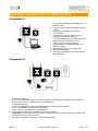
Connection examples and installation notes
CompleteSet 1
1. Connect AlarmManager and MultiSensor via
Modular cable.
2. Connect power supply to AlarmManager and
current.
3. Download, install and execute Kentix
ControlCenter.
(Software-Download on www.kentix.de)
4. Enter Kentix-Default-IP-Address
(192.168.100.222) and the default user data
(admin/password) and press „Login“.
(check your own network-settings).
5. Setup IP-Address of AlarmManager in the
Network settings.
6. Add Radio Sensor in „Sensor-Devices“.
7. Make individual setup.
8. Save the Configuration to transfer it into the
AlarmManager.
CompleteSet 2
1. CompleteSet-BASIC 2:
Connect the KIO-Power-Adapter to the power supply and attach the two MultiSensors via Modular
Cable. Follow steps 2 to 8 described for „CompleteSet 1“.
CompleteSet-PRO 2:
Connect the MultiSensor-RF with the AlarmManager or the KIO-Power-Adapter.
Connect the MultiSensor-LAN with a PoE-Switch.
Follow steps 2 to 8 described for „CompleteSet 1“.
2. The KeyPad is added to the configuration like a Radio Sensor.
!! Important: For detection during the setup of the KeyPad it has to be kept active by pressing one of
the function keys for every 5 seconds.
3. Save the Configuration to transfer it into the AlarmManager.
Page 5
!
!
!
!
(08-2014, subject to change)
kentix.de
CompleteSet with optional equipment
KMS-Door
1. MultiSensor-LAN:
Establish network connection and external power supply, if needed.
Connect to the sensor via browser by entering the Default-IP (192.168.100.223).
Press „Login“ to reach configurations menu (Username: „admin“, Password: „password“).
Activate AlarmManager communication in the network-section.
After saving the settings and a restart, the sensor can be configured with the Kentix ControlCenter.
2. Leakage-Sensor:
The connection of a Leakage-Sensor is realized with a KIO-Power-Adapter,
either to the system-connector of a MultiSensor or the AlarmManager.
3. MultiSensor-Door:
Start the teach-in process to add new radio devices in the ControlCenter.
Press the „learn button“ of the sensor and keep it pressed.
When pressing the button, the sensors plays a long sound which is repeated after about 5 seconds.
Release the button after the second sound. The sensor should appear in the list after about 20 seconds
and is configured automatically with the default settings. The successful configuration is signalized by a
green checkmark.
Page 6
!
!
!
!
(08-2014, subject to change)
kentix.de
Alarm-inputs
When installing the device follow the instructions in this manual. Please note polarity and technical data of
the inputs.
Relay contacts
When installing the device follow the instructions listed in this manual.
Connected devices must installed properly following the specifications in this manual. Pay particular attention
to the allowed supply voltages and services for the various consumers in the technical data-sheet.
Power supply
The devices are supplied with a DC voltage between 10-32VDC. Use only recommended power supplies or
listed power supplies in this document. The polarity of the cable must not be interchanged. According to the
two operation types "Plug'n Play" and "fixed installation", you can power devices from the plug power supply
or via a fixed connection.
Example 1: Power supply of one MultiSensor via the system jack of the AlarmManager
Example 2: Power supply of two MultiSensors via Power Adapter (KIO1) and plug power supply
Electronic equipment is not domestic waste - in accordance with directive 2002/96/EC OF THE
EUROPEAN PARLIAMENT AND THE COUNCIL dated 27th January 2003 concerning used electrical
and electronic appliances, it must be disposed of properly. At the end of its service life, take this unit for
disposal at a designated public collection point.
Spent batteries are special waste!
Do not throw spent batteries into your domestic waste; take them to a collection point for spent batteries.
The products complies with applicable European standards and directives and is confirmed by the CE
mark.
The CE conformity declaration is available on request.
Page 7
!
!
!
!
(08-2014, subject to change)
kentix.de
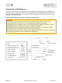
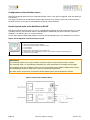
Overview KENTIX System Topology
✓ The AlarmManager is the central unit.
With the BASIC-Version up to 10 MultiSensors and 3 KeyPad wall-mount keyboards
can be connected. The PRO-Version supports up to 100 devices (MultiSensors-RF/-LAN/-RACK/LAN-RF/-Door and KeyPads).
✓ The KENTIX components are communicating via radio (ZigBee ®) in the 2.4GHz ISM band.
The MultiSensors and KeyPads are working in a mesh network and communicate with each other.
✓ Start each new project always with a CompleteSet. The Sets include everything you need
for the plug'n play installation. Select the Set according to your project size.
✓ You can expand the CompleteSets with the extension parts and accessories at any time.
Mobile phone
KENTIX system-components
2
3
n
MultiSensor
1
2
KENTIX System jack
n
KeyPad
POWER
GSM
ZigBee®
1
KIO1
Connection examples Ext.-Alarm
MultiSensor-LAN (PRO-Version only)
Default IP-Adr.: ! 192.168.100.223
Subnet-mask:! 255.255.255.0
LAN
POWER
AlarmManager-BASIC/PRO
Default IP-Adr.: ! 192.168.100.222
Subnet-mask:! 255.255.255.0
HVAC
Leakage-Sensor
UPS
Page 8
!
!
!
!
(08-2014, subject to change)
kentix.de
AlarmManager-BASIC/PRO
Login to the AlarmManager
The PC-Client Kentix ControlCenter displays a Login-screen after starting the Application.
To log in, enter IP-Address and user data for your AlarmManager.
With the first commissioning, use the default IP-Address 192.168.100.222
and the user data admin/password to log in.
NOTE
Only users with the permission „Administrator“ are allowed to make changes to the AlarmManager.
For users without the admin permission, only the tab pages „Dashboard - Logbook - Monitoring“ are
available for viewing purposes.
Changing IP-Settings
Connection with PC:!
!
!
!
!
!
!
Connect the LAN interface of the AlarmManager via the supplied LAN cable to your
PC. Note that a direct connection needs the supplied crossover adapter. Set the IP
address of your PC for example to "192.168.100.123".
Note that changes in the IP-Settings get active directly after applying.
A wrong configuration can set the AlarmManager to a state where it is only accessible via direct connection.
IMPORTANT!
If you forgot the IP-address of the AlarmManager connect it with the crossover cable directly to the LAN
port of your PC. Open the Network settings in the ControlCenter to show the current IP address. You may
have to disable the firewall and also additional network cards of the PC.
Default settings / Factory defaults
Default IP-address: !
Subnet mask:! !
User:! !
!
Password:!
!
192.168.100.222
255.255.255.0
admin
password
Setup IP-Address:!
!
!
!
Change IP settings in the Kentix Control center opening „Settings - Network...“
in the menu.
Reset to factory defaults
To reset the AlarmManager to factory defaults, press the RESET Button on the back of the board and hold
it down for 5 seconds. The device will be set to factory defaults and restarts. After about 30 seconds the
AlarmManager can be accessed again via the default settings.
(NOTE: This function is valid for all AlarmManager-BASIC/PRO from 01/2014 on)
Page 9
!
!
!
!
(08-2014, subject to change)
kentix.de
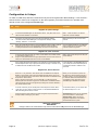
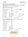
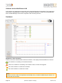
Configuration in 8 steps
To make an initial setup with the ControlCenter only the three register-tabs "Base-Settings - User Accounts Sensor-Devices“ have to be configured. On the other registers you find the functions for operation and
remote control of the configured AlarmManager.
No
Step
Comment
Register tab „Base settings“
1
Connect the AlarmManager via LAN cable to the PC. The yellow LED on the
LAN connector indicates a connection.
With 1:1 LAN connection via network
cable use crossover-adapter
2
Start Kentix ControlCenter and connect with the default IP-address
192.168.100.222 to AlarmManager. To change the IP settings, select
„Settings - Network...“ in the menu.
Make sure that your PC is in the same
network.
3
Enter the mobile data according to the used SIM card. When a PIN is used for
the SIM card, first „Save“ your configuration with the correct PIN before
inserting the SIM card into the AlarmManager to avoid a lock of the card.
You can disable the PIN of your SIM card
with a mobile phone. The entries in the
software will then be ignored.
Register tab „User accounts“
4
5
In the first user account enter your name, e-mail-address and mobile number
in international notation (+49 ...).
Assign an user password and a 4-digit Operator-PIN. The first user account is
always the "Administrator Account" and can not be deleted.
With a right mouse click you can test your
mobile settings.
Using a KeyPad the PIN also applies to the operation via the keyboard. Note
that the KeyPad allows only 4-digit passwords with the digits 1-9. When using
an RFID card enter the RFID card number.
In the operation of the AlarmManager via
your mobile phone the transmitted phone
number will be check in addition to the
password.
Register tab „Sensor-Devices“
6
Press the "+" key to teach-in new devices such as MultiSensor or KeyPad.
BASIC: A new window opens and all accessible devices appear as soon as
you press the „learn button“ at the device. After all devices are available in the
list press the "Save" button.
PRO: A windows opens where you can select RF- or LAN-components.
Selecting RF starts the scanning process as described in the BASIC-Version.
LAN-components have to be configured by entering the correct IP-address in
the „device address“-field.
When you run the teach-in process for
RF-devices a closed wireless network is
created, similar to an encrypted wireless
PC network. Make sure that the devices
are located in radio range close to the
AlarmManager / MultiSensor-LAN-RF.
7
In the list of devices you can already test functionality of the device. With a
"right click" you get a choice of test functions. Let the selected MultiSensor
LED flash and give the device a name.
Via the test functions you can switch also
the external outputs on or off.
Finally change the alarm settings and alarm assignments (Armed-Active /
Always-Active) according to your needs.
Armed-Active: Alarms are only triggered,
when the system is in armed state.
Always-Active: Alarms are always
triggered, independent of the armed/
disarmed state of the system
8
Saving the configuration
IMPORTANT!
Changes made in the ControlCenter only become active when being saved into the AlarmManager.
Page 10
!
!
!
!
(08-2014, subject to change)
kentix.de
Visual and acoustic signaling
AlarmManager
!
!
LED-POWER: !
LED-GSM:!
!
!
LED-ARMED:!
LED-ALARM: !
!
!
!
!
!
!
Lights after connection to the power supply
Flashes: Booked into GSM network, ready for communication.
Constant: No GSM network connection, no communication possible
Lights if AlarmManager is armed
Lights if an alarm is triggered
!
!
MultiSensor-RF / -LAN / -LAN-RF
LED-GREEN: !
!
!
LED-RED: !
!
!
!
!
!
!
!
Lights if MultiSensor is powered and function is OK (not in stealth mode)
Lights after power lost for around 3 minutes.
Constant: MultiSensor is armed
Flashes: An alarm was triggered
!
!
MultiSensor-RF / -LAN / -LAN-RF and AlarmManager
BUZZER:!
!
!
!
!
!
!
!
!
!
!
!
!
!
!
Alternating: Arm delay is running.
Delay is depending on configured time in the ControlCenter.
Constant of 1 Second: System has been disarmed.
Constant of 3 Seconds: Arming was not executed - alarms are existing. Please check
external alarm inputs on AlarmManager or MultiSensor.
!
!
MultiSensor-Door
!
Normal operation mode:
LED-RED: !
!
LED-GREEN: ! !
BUZZER:!
!
!
!
!
blinking 1x per routine message in case of alarm
OFF
1x short in case of alarm
1x short when pressing the teach-in button (Sensor identification)
Teach-In process:
LED-RED: !
!
LED-GRÜN:!
!
!
!
!
BUZZER:!
!
!
!
!
OFF
long blinking: Teach-In process started
ON: Teach-In process completed
1x short when pressing and holding down the teach-in button
additionally 1x long after 5 seconds
!
MultiSensor-RACK-MINI
!
!
Normal operation mode:
LED-RED: !
!
short blinking: armed
!
!
!
OFF: disarmed
!
!
!
long blinking: alarm
LED-GREEN: ! !
short blinking: disarmed
BUZZER:!
!
1x short in case of alarm
!
!
!
1x short when pressing the teach-in button (Sensor identification)
Teach-In process:
LED-RED: !
!
LED-GREEN: ! !
!
!
!
BUZZER:!
!
!
!
!
OFF
long blinking: Teach-In process started
ON: Teach-In process completed
1x short when pressing and holding down the teach-in button
additionally 1x long after 5 seconds
Page 11
!
!
!
!
(08-2014, subject to change)
kentix.de
Alarm zones
MultiSensors connected to the AlarmManager and also the inputs of Kentix IO-modules can be assigned to
different alarm zones. With this option a separation into different areas can be realized. Every zone can be
switched to armed or disarmed state and send alarms independent from the other alarm zones.
For the configuration, add the desired number of zones in the alarm zones section of the base settings and
enter a name for every zone. After this assign the sensors to the desired zone.
IMPORTANT!
Also with multiple sensors in one zone an alarm of the type „Armed-Active“ can only be reported once for
every zone. After alarming the alarm repetition is activated. If a continuous alarming is desired, the
automatic quitting of alarms can be activated in the advanced settings.
The Quitting (by Software/Web-Interface/SMS/App) of alarms always considers all alarms regardless of the
assigned alarm zone.
Quitting Alarms
When an Armed-Active or Always-Active alarm is triggered at the AlarmManager, it has to be quit after the
cause has been fixed. This can be done by the Web-Interface, the ControlCenter, via SMS or with the App.
IMPORTANT!
Only when an alarm has been quit, it can be triggered again.
Other following alarms with a different cause from the sensors are still reported without acknowledgement.
The last triggered alarm will be resent every time the set up time for the alarm repetition runs up. With a
value of 0 this repetition can be suppressed.
If an existing alarm is quit without the cause being fixed, the AlarmManager stops the alarm repetition. The
alarm state stays active.
Additionally the AlarmManager tries for every 6 hours to quit existing alarms. When the cause has been fixed
or is no longer present, alarming can be stopped this way, but gives the possibility to be re-triggered again.
Page 12
!
!
!
!
(08-2014, subject to change)
kentix.de
User accounts
In the user accounts the setup of the permissions and the alarming is done.
Only if the required user data is entered, a user can control the AlarmManager or request information.
The list describes the user data required for AlarmManager interaction:
Input field
Description
User Password
Login to the ControlCenter, the Web-Interface and the Kentix App
PIN-Code
Remote control by SMS and switching via KeyPad
E-Mail Address
Destination address for the alarming
Phone number
Destination phone number for the alarming. Also used as authentication for the SMS controlling.
Assigned alarm zones
The user can only switch zones assigned to his account. To switch all zones together, every zone has
to be assigned to the user.
Permissions
Assign single permissions for the user by activating the according option.
IMPORTANT!
Only users with the permission „Administrator“ are allowed to make changes to the AlarmManager.
For users without the admin permission, only the tab pages „Dashboard - Logbook - Monitoring“ are
available for viewing purposes.
A login on the web interface is also not permitted.
Page 13
!
!
!
!
(08-2014, subject to change)
kentix.de
SMS commands for remote control of AlarmManager
The AlarmManager reports not only all the alarms via SMS, it can be also remotely controlled via simple
SMS commands from a mobile phone. This brings the big advantage of having the central alarm system in
your pocket and remotely setting the system to the desired states.
The AlarmManager can be armed or disarmed and alarms can be acknowledged remotely. So you can
decide if it is necessary to intervene on the ground at any time by using the SMS information and status
inquiry.
Important notes for remote control of the AlarmManagers via SMS
•
•
•
•
•
Upper- and lower-case can be used.
Between „Operator-PIN“ and „COMMAND“ is always a space.
The „Operator-PIN“ can have 4-8 alphanumerical characters. Setup the PIN with the ControlCenter.
The AlarmManager is confirming each command SMS with an SMS back to the sender.
Command SMS with the wrong phone number or password will not be confirmed for security reasons.
SMS control commands
SMS command
Description
Example
Confirmation
{PIN} ON
Arming of the AlarmManagers. All zones will be
armed..
1234 on
OK! ARM All Zones
{PIN} ON{ZONE}
Arming of the selected zone.
1234 on1
OK! ARM ZONE 1
{PIN} OFF
Disarming of all zones.
1234 off
OK! DISARM All Zones
{PIN} QUIT
Acknowledge of all pending alarms. The alarm
repetition is terminated.
The AlarmManager can be set to arm state again.
1234 quit
OK! ALARM QUIT
{PIN} STATE
The AlarmManager sends the actual system
state.
1234 state
OK! ARMED/DISARMED/
ALARM
The AlarmManager sends the actual system state
and values of a MultiSensor.
Enter the number of the MultiSensor (1-100)
directly after the command „MSTATE“.
The response contains the name of the
MultiSensor.
{PIN} MSTATE1-n
OK! SENSORNAME:
1234 mstate1
TEMP=20C
REL-HUM=25%
DEW-POINT=3C
MOTION=15%
EXT-IN=0
SABOTAGE=0
POWER=OK
NOTE!
When a sensor sends an alarm, the SMS contains the number of the sensor to send a mstate request.
!
!
Example: Arm-disarming of the AlarmManager via SMS command
1234 on
SMS command
OK! ARM ZONE 123
SMS answer
Page 14
!
!
!
!
(08-2014, subject to change)
kentix.de
Advanced settings - AlarmManager-BASIC and -PRO
In the advanced settings, additional functions of the AlarmManager can be activated.
General Settings
Backup folder
The path to the backup of the AlarmManager configurations-file is set here.
Alarm functions
Setup the behavior of the AlarmManager for existing alarms here. The acoustic feedback (buzzers of
AlarmManager and MultiSensors) can be activated or deactivated as needed, except the CO-alarming. A
CO-alarm always triggers all buzzers for the setup buzzer time.
E-Mail & SNMP
For E-Mail alerting an account with or without user access data can be entered. Depending on the E-mail
server, a encryption method might be necessary. When choosing an encryption mode (STARTTLS / SSL) the
required port will be set to the default port. The port can be changed to another one when needed.
Enter the IP-address of the E-Mail server and the senders address here.
Receive the IP-address of the E-Mail server by entering the domain and pressing the button „DNS -> IP“.
With the Kentix-Check-Button a test E-Mail with the E-Mail-Data can be sent.
NOTE!
The test e-mail is sent to the e-mail-address of the first user. In case of an error please check, whether an
e-mail-address has already been configured for this user. Also take care of possible restrictions (Routing/
Firewalls) in your network and synchronize data like encryption and communication port with the
responsible persons.
The AlarmManager supports full SNMP-functionality. Alarms can be sent as traps. Additionally the
AlarmManager can be configured for requests via Network Monitoring systems. For this purpose you can
download a MIB (Management Information Base) for the SNMP-Host.
SNMP-Trap to SMS Gateway
The AlarmManager (PRO only) can send incoming SNMP-Traps as SMS to the configured users.
Therefor a list of permitted hosts can be created in the section „SNMP - Trap to SMS“.
When a SNMP-Trap is received by the AlarmManager, the content of the trap is sent together with the
assigned name to all users that are activated for receiving Always-Active alarms.
Server Monitoring
Define up to 20 servers (BASIC 3 servers) with IP address and the network port to be monitored. A selection
of ports is available via the pulldown-menu, but also a free port can be specified.
The AlarmManager makes cyclic tests, if the specified ports on the servers are available.
The request interval can be set between 60 and 999 seconds. Note that the alarm will first be triggered after
3 fail attempts with the specified interval.
By pressing the Kentix-Check-Button the connection to the server in the selected line can be tested.
Page 15
!
!
!
!
(08-2014, subject to change)
kentix.de
Advanced settings - AlarmManager-PRO only
Network Cameras
The AlarmManager-PRO can control cameras in its network to start the recording of a video or picture
(depends on the camera features). Enter the IP-address and the port of the camera here.
Take the command to start a recording out of the cameras documentation.
Enter the command as an URL without entering the IP-address in the command-field (e.g. „/command=...“).
For Mobotix and AXIS cameras predefined commands can be chosen via the pulldown menu.
Check the camera setup by pressing the Kentix-Check-Button in this line.
External Alarms
The AlarmManager-PRO can be extended by additional digital Inputs and Outputs via special Expansion
modules (KIO7052 or KIO7053).
With these it is possible to monitor up to 96 more alarms e.g. air-conditioning-systems, extinguishing
systems, USVs or other alarm detection systems.
For configuration regard the instructions in the „Enhancements“ section and the corresponding Data sheets.
SMS gateway function of AlarmManager
External applications such as Network monitoring systems can send via the AlarmManager-PRO SMS text
messages via the integrated modem. Communication is carried out via the build-in web server and the
HTTP protocol. Following HTTP call is necessary:
HTTP (Port80)
Application
SMS
(SMS-Message)
Replace the variables with your data. You can send a test SMS from any web-browser.
HTTP command structure:
http://AlarmManager-IP/sendmsg?user=myUser&password=myPassword&to=012341234567&text=myText
AlarmManager-IP!
myUser!
!
myPassword! !
0049...! !
!
!
!
!
!
!
!
myText!!
!
IP address of the AlarmManager (Default 192.168.100.222)
Username (User with access right to send SMS messages)
Password
Mobile number in national or international notation
To use the character „+“ in the URL please replace it with „%2B“
Exp.: „+49“ replaced with „%2B49“
Text-message with up to 160 characters
HTTP return code: !
!
!
!
200 when SMS sending was successful
300 when SMS sending was unsuccessful
Page 16
!
!
!
!
(08-2014, subject to change)
kentix.de
MIB for SNMP-Systems
For the AlarmManager-PRO a MIB (Management Information Base) is available, which describes the
information that can be requested or modified by a SNMP-System (z.B. PRTG, OpManager or WhatsUp
Gold). The single values in it are identified and requested via the OID (Object Identifier). Every value has his
own specific OID.
The following list shows the structure of the AlarmManager-MIB and gives an overview of the values that can
be requested:
๏ state
- alarm1
- alarm2
- ...
state - System state:
Query branch of the AlarmManagers general system state.
Delivers the actual state as shown in the Web-Interface or
the Dashboard of the ControlCenter (e.g. Arm/Disarm,
Alarm1 (Armed-Active), Alarm2 (Always-Active), Fire, Server
state,...).
๏ multisensors
• multisensor01
- sensorname01
- temperature01
- humidity01
- dewpoint01
- co01
- motion01
- digitalin101
- digitalin201
- digitalout201
- comError01
• ...
• multisensor100
multisensors - MultiSensors RF/LAN:
Query branch for the values of all connected MultiSensors
(the branch shows all 100 maximum possible Sensors).
All values are displayed as integers, whereas temperature
and dew point are increased by a factor of 10, to consider
one more decimal place. This has to be taken into
consideration in the requesting SNMP-System.
๏ ext-module
• modul01port01
-
•
•
portname
portstate
ext-module - Module for external alarms:
Query branch for the In- and Outputs of the external modules
KIO7052/3.
Shows the configured name and the actual alarm state for
every In- and Output respectively at Outputs the switched
state.
...
modul06port16
๏ server-monitoring
• server01
-
servername01
...
serverstate01
•
•
...
server20
๏ alarm-zones
• alarmzone01
alarmzonename01
alarmzonestate01
alarmzonealarm101
• ...
• alarmzone30
Examples for the OID:
AlarmManager OID: !
Query branch „state“: !
Object „alarm1“:! !
server-monitoring - State of the monitored Servers
Query branch of the configured servers to be monitored.
Shows the configured name, IP-address and port of the
service to be monitored, the response time in milliseconds
and the alarm state (0-OK, 1-not reachable) for every server.
.1.3.6.1.4.1.37954.1
.1.3.6.1.4.1.37954.1.1
.1.3.6.1.4.1.37954.1.1.4.0 - shows the actual state for alarm 1 (armed-active)
Query branch multisensors:
.1.3.6.1.4.1.37954.1.2
Lower branch multisensor01: .1.3.6.1.4.1.37954.1.2.1
Objekt „temperature01“:!
.1.3.6.1.4.1.37954.1.2.1.2.0 - shows actual temperature value of the 1st MultiSensor
Page 17
!
!
!
!
(08-2014, subject to change)
kentix.de
Execution of Firmware Updates
We are always looking to include innovations of development in our products and to ensure their faultless
operation. Therefor we release updates in regular intervals.
To execute an update pay attention to the following steps.
No
Step
Comment
1
Download the actual version of the Kentix ControlCenter from the
Kentix Website and install it.
Find the software in the „Info & Support“ section under „Software &
Manuals“.
The software works for the BASIC- and PROVersion of the AlarmManager and includes all
necessary update components.
2
Start the software and connect to your AlarmManager by entering the
IP-address and user date and clicking „Connect“.
A popup-window appears indicating an existing
firmware update.
3
Start the update process by selecting „Yes“ in the popup-window.
Before the update the AlarmManager starts a download of the actual
configuration and loads it back into the device after the updating is
completed.
Running a firmware update will overwrite all saved
data (except IP-settings) on the AlarmManager.
If the update process fails, restart it by pressing
the „Login“ button again.
4
When the update is finished, login to the AlarmManager with the
default login user data (admin/password). Change the user data of
the first user back to your desired settings.
After Saving, the AlarmManager is on the newest
firmware state with your personal configured data.
Page 18
!
!
!
!
(08-2014, subject to change)
kentix.de
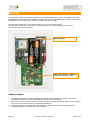
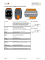
Connections - AlarmManager-BASIC/PRO
GSM
ZigBee®
According to the two types of installation "Plug‘n Play" or "wired connection" you will find all connections of
the AlarmManager in the following overview. With the "Plug'n Play" installation you only need to open the
case to insert the SIM card. Pull the sides of the case a bit apart. The cover slips right out of the groove and
can easily be lifted off. You can insert the fixed connection cable from the rear of the chassis. Break out the
push-out marking from the inside with a screwdriver.
The terminal is designed for wire sizes up to 0.8 mm ².
SMA
SMA
SIM mobile card.
Insert the card with the contacts to the
bottom (perforation down right) and close
the SIM holder.
IMPORTANT! Only insert the SIM card after
the initial configuration with a first PIN has
been uploaded.
POWER
ALARM
GSM
ARMED
12
LAN
10/100Mbit
KENTIX
system jack
Power
10-32VDC
KENTIX
system jack
1
Kentix system jack
Page 19
!
!
!
!
Push-Out
Cableinsertion
Internal terminal 12 pole:
12 - GND
11 - Relay ALARM Armed-Active (NC)
10 - Relay ALARM Armed-Active (NO)
9 - Relay ALARM Armed-Active (COM)
8 - Relay ALARM Always-Active (NC)
7 - Relay ALARM Always-Active (NO)
6 - Relay ALARM Always-Active (COM)
5 - Power supply 10-32VDC (+/-)
4 - Power supply 10-32VDC (+/-)
3 - Ext. alarm input
2 - Ext. arm-disarm
1 - Internal system voltage (5V)
1 - GND
2 - DO1-LED
3 - DO2-LED
4 - Power supply 10-32VDC (+/-)
5 - Power supply 10-32VDC (+/-)
6 - Ext. alarm input (External dry contact, no/nc)
7 - Ext. arm-disarm (External dry contact, no/nc)
8 - 5V internal system voltage
(08-2014, subject to change)
kentix.de
External I/Os AlarmManager-BASIC/PRO
Examples of the external circuit of the AlarmManager. Shows the internal 12-pin terminal of the AlarmManager. The
internal circuit of inputs and outputs is shown schematically for better understanding. The logic of the alarm inputs can be
rotated in the ControlCenter.
Example 1: Wired with power supply via the internal 12-pin terminal.
Example 2: Power supply via the external plug supply, just the alarm-inputs are connected.
Description - Relay-Contacts:
Alarm 1 : Armed-Active
Alarm 2 : Always-Active
Page 20
!
!
!
!
(08-2014, subject to change)
kentix.de
License Management
In contrast to the AlarmManager-BASIC, the PRO-version contains additional useful features like e.g.
connecting network-enabled MultiSensors or adding IO-modules.
Having the same technical design, there is the possibility to upgrade an AlarmManager-BASIC via a license
key to the PRO-Version with the Kentix ControlCenter, if required.
A valid license key can be purchased via our sales department (s.a. www.kentix.de).
Page 21
!
!
!
!
(08-2014, subject to change)
kentix.de
MultiSensors
According to the two types of installation "Plug‘n Play" or "wired connection" you can find all connections of
the MultiSensor in the following overview. To remove the cover pull the sides of the case a bit apart. The
cover slips right out of the groove and can easily be lifted off (see section 5.6 - „How to open the
MultiSensor“). You can push the RF „learn button“ or insert the fixed connection cable from the rear of the
chassis. Break out the push-out marking from the inside out with a screwdriver. The spring-terminal is
designed for wire sizes up to 0.8 mm ². Use a screwdriver for slotted grub screws to fix the wires. They can
be inserted and removed without force.
Mounting instructions for MultiSensor-RF / -LAN / -LAN-RF
The MultiSensor is equipped with various individual sensors. To get an optimal sensitivity and function of the
sensors, please note the following installation instructions.
Note the following instructions:
• Do not install close to heaters or direct heat.
• Avoid detection of moving objects such as fans, plants, trees, flags, etc.
• Don´t cover the Sensor. The PIR-Sensor needs inter-visibility for detection.
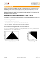
Coverage of the integrated PIR movement detector
The range of the MultiSensor is depending on the configured sensitivity about 8m. You get the best results,
when objects/persons move past the MultiSensor.
ceiling suspension
Page 22
!
!
!
!
wall fastening
(08-2014, subject to change)
kentix.de
External I/Os of MultiSensors
Examples of external circuits of the MultiSensors. This shows the internal 8-pin terminal of the MultiSensor.
The internal circuit of inputs and outputs is shown schematically for better understanding. The logic of the
alarm inputs can be rotated in the ControlCenter. Running in standalone mode, this is also possible via the
MultiSensor-LANs web interface.
Example: Wired connection with power supply via internal terminal.
IMPORTANT!
The switching outputs 6/7 are open collector transistor outputs and the maximum load is 100mA.
For plug´n play use of the outputs you can choose KENTIX module: KIO1 Power-Adapter
The switching output 6 in standalone mode can only be activated via the SNMP or SMS remote function.
In AlarmManager mode the output can be used for arm/disarm signalization.
The switching output 7 is automatically switched by an alarm (Armed-Active or Always-Active) trigger.
The alarm inputs 2/3 can be directly connected with potential-free contacts.
When using the system jack for power supply you can switch the alarm inputs 6/7 direct to the pin 8 (GND)
of the internal 8-pin terminal. See also example 2 for the MultiSensor.
Page 23
!
!
!
!
(08-2014, subject to change)
kentix.de
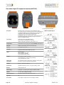
MultiSensor-RF
It is not necessary to configure the MultiSensor-RF. Updating it is also not necessary/possible.
For the setup of a MultiSensor-RF follow the steps in the configuration on page 9.
Learn Button between PCB and chassis.
IMPORTANT! Operating the learn-button just with
an non conducting, flat object. Otherwise it may
short circuits.
CO gas sensor
LED yellow - Run/Power
LED red! - Constant light: armed
!
- Flash light: Alarm trigger
Kentix system jack for Plug´n Play connection,
power supply and external system devices.
Connector
PIR-Sensor
8
1
Internal terminal strip 8-pole:
8 - GND
7 - Relay ALARM (Open Collector 100mA)
6 - Switching Relay (Open Collector 100mA)
5 - Power supply 10-32VDC (+/-)
4 - power supply 10-32VDC (+/-)
3 - Ext. alarm input (External dry contact)
2 - Ext. sabotage alarm (External dry contact)
1 - GND
Antenna
Push-Out
cable-insertion
Kentix Systembuchse
1 - GND
2 - Alarm output (Open Collector 100mA)
3 - Remote switch output (Open Collector 100mA)
4 - Power supply 10-32VDC (+/-)
5 - Power supply 10-32VDC (+/-)
6 - Ext. alarm input (External dry contact, nc/no)
7 - Ext. sabotage alarm (External dry contact, nc/no)
8 - 5V internal system voltage
Adding a MultiSensor-RF
1. For adding a MultiSensor-RF to the AlarmManagers configuration start the teach-in process in the Kentix
ControlCenter and press the „learn button“ for 1 second. The button can be accessed via the hole in the
cases back.
2. The sensor should appear in the list after approx. 15-20 seconds and is configured automatically.
3. The teach-in process is completed when the sensor is marked in the list with a green checkmark.
4. Click on Apply for completion to add the MultiSensor to the devices list.
Page 24
!
!
!
!
(08-2014, subject to change)
kentix.de
MultiSensor-LAN
In contrast to the MultiSensor-RF with radio interface the MultiSensor-LAN can also be used stand-alone
without an AlarmManager. For configuration in stand-alone operation a web server is integrated, which
allows you to configure the device via LAN and a web browser. With the SNMP interface, an integration in
network management systems is possible.
Connection via PC:!
!
!
!
!
!
!
Connect the LAN jack of the MultiSensor-LAN with your network and your PC
using a LAN cable. Please note that you have to use a Cross-Over network cable for
a direct connection. Set the IP address of your PC to e.g. „192.168.100.123“.
Default settings / Factory defaults
Voltage supply:!!
Default IP-address: !
Subnet mask:! !
User:! !
!
Password:!
!
PoE (Power over Ethernet). Change to external power supply possible.
192.168.100.223
255.255.255.0
admin
password
Important! Reset to factory defaults
If you forgot IP-address or the login information of the MultiSensor-LAN, press the RESET button at the
back of the sensor. The device will reset to factory defaults and reboot. After 30 seconds the MultiSensor
can be accessed with the default IP-address and default user data.
Change power supply from PoE to external
By default, the MultiSensor-LAN is set to the power supply over PoE (power over ethernet).
So, you can operate the device without another power supply direct by a PoE capable switch. The market
standard PoE injectors can also be used for power supply.
To operate MultiSensor-LAN over an external power supply, you have to change a jumper (Jumper JP1) on
the platine. Pay attention to the picture below, for switching the jumper.
Changing power supply:
PoE:
Jumper to 1 + 2 (POE)
External: Jumper to 2 + 3 (EXT)
IMPORTANT!
Do not change the jumper while
the device is under tension.
Disconnect the device always
from network and power supply.
Page 25
!
!
!
!
(08-2014, subject to change)
kentix.de
Software function MultiSensor-LAN
In the following, the stand-alone functionality of the integrated web server is described. For the described
functionality no AlarmManager is required. When operating the MultiSensor-LAN with the AlarmManagerPRO, the AlarmManager controls the configuration and monitoring functions.
Dashboard
MultiSensor values and status:
Display of the sensor measurements and alarm conditions. This display will be actualized all 5 seconds.
- No underflow or exceeding of the measured values
- There is an underflow or exceeding of the measure value, an alarm was triggered
- The motion detection is switched to Disarmed
- The motion detection is switched to Armed
NOTE!
The Sensor records a value for temperature and humidity every 10 minutes. Additionally the values in an
alert case are also recorded.
Page 26
!
!
!
!
(08-2014, subject to change)
kentix.de
Navigation
Dashboard!
Login! !
Configuration!
System!!
!
!
!
!
Help ! !
Logout! !
!
!
!
!
!
!
!
!
- Starting page with measurement table, control of the 2nd digital output, logbook
- User login
- Basic configuration, MultiSensor (Sensor- and alarm settings), Users (Login,E-Mail)
- System information (software version), test functions, configuration management,
firmware update, device reset
- logbook
- Help and support information
- User logout
Configuration - Basic configuration
Device name
Configuration of the device name, this name can be chosen freely.
Language
Select the displayed language of the MultiSensor‘s Website.
You can choose between german and english language.
Temperature unit
Switches the temperature evaluation and display of the MultiSensor-LAN between celsius and fahrenheit.
IP address / network mask / gateway
Network configuration of the MultiSensor.
If you need the MAC address of the MultiSensor for your router or firewall settings, you will find it on the
network jack when opening the device.
DNS1/2 (Domain Name Server Addresses)
Enter the name server address. Depending on network configuration e.g. on use of an ADSL router it can be
the gateway address.
Public DNS servers: 8.8.8.8 or 8.8.8.4
NTP1/2
Configuration of the time server (network time protocol). The NTP configuration is needed if you use the
time-controlled arming and disarming.
Public NTP servers: 0.de.pool.ntp.org or 1.de.pool.ntp.org
IP-address and activation of AlarmManager communication
Activate the communication with the Kentix AlarmManager-PRO here. Enter the IP-address of the
AlarmManager and activate the checkbox.
Der AlarmManager-PRO takes control of the configuration of the MultiSensors alarm settings.
The local alarm- / threshold values are then inactive.
FTP server activation
The integrated FTP server can be activated or deactivated. The FTP access will be needed for a software
update of devices with an old firmware version (< 4.00.00). Look up in the chapter „software update“ for it.
When changing the network settings, the MultiSensor automatically performs a reset.
Page 27
!
!
!
!
(08-2014, subject to change)
kentix.de
E-Mail
If the MultiSensor should be able to send e-mails in the case of alarm to a configured user, it is necessary to
set an e-mail server (SMTP or ESMTP). When you have set a DNS server, which is configured in the DNS
settings, you can use the DNS name of the e-mail server here. With using ESMTP you can here enter the email access data, which you can obtain from your e-mail provider. Depending on the E-mail server, a
encryption method might be necessary. When choosing an encryption mode (STARTTLS / SSL) the required
port will be set to the default port. The port can be changed to another one when needed.
Pay attention that many mail servers need an existing sender address to send an e-mail correctly.
In the subject of the e-mail the corresponding alarm text can be found and in the mail text all measurements
from the MultiSensor are included.
E-Mail Signature
Enter a signature, which is sent with every alarm E-Mail. The signature is limited to 300 signs length.
SNMP settings
Configuration of the Simple Network Management Protocols. The MultiSensor-LAN is able to send alarm
messages as SNMP-Traps. Enter both SNMP host addresses for this. Further the sensor can be prompted
or partially configured via SNMP. The functions which are available for the SNMP communication are
specified in the supplied MIB (Management Information Base). It is available on the integrated FTP server or
as download from the Kentix website.
Configuration - MultiSensor (Sensor- and alarm settings)
In the following settings you can set the limit and action values for the alerting.
When an alarm is triggered, an e-mail will be sent to the configured persons and the internal buzzer is
activated.
Sensor-Temperature, Humidity, Dew-point
Set the alarm limit values. Alarm will be triggered when the measurements undershot or exceeded the limits.
The temperature hysteresis is 1°C, humidity hysteresis 1%.
The dew-point is calculated with the current temperature and the relative humidity from the sensor.
If the room temperature approximates to the difference of the set dew-point hysteresis (2°C default) an alarm
will be triggered. Systems and devices can lead to condensation, when the dew point temperature
approximates the room temperature.
Sensor-Carbon Monoxide
Alarm settings for the Carbon Monoxide. The sensitivity can be set from 0% to 100% and will be triggered
by exceeding. CO is measured from about 10ppm. There is no exact measurement of the CO content. The
measurement is construed to the highest sensitivity and can be changed slightly in the adjustment.
Carbon Monoxide concentrations like they emerge in fires are detected even at 100% setting.
10%: Minimal concentration of around 10-50ppm lead to an alarm trigger.
100%: Concentrations of 200-400ppm lead to an alarm trigger.
Sensor-Motion
Limit value for the integrated PIR (passive infra-rot) motion detection. It is triggered when exceeded. Objects
which have a temperature difference of about 4°C to the environment temperature and which are bigger than
250x400mm will be detected. For a safe detection of persons, the value should be in the range of 30-50%.
The detection range is about 100°.
Page 28
!
!
!
!
(08-2014, subject to change)
kentix.de
Sensor-Vibration
Alarm settings for the sensitivity of the internal vibration sensor. The sensitivity can be adjusted in 3 levels.
If necessary the vibration sensor can also be completely turned of.
NOTE!
The vibration sensor in the MultiSensor is first available in devices delivered in 01/2014 or later.
Arm-Disarm time
Switching time for the time-controlled arming and disarming from the integrated motion detection.
To use it, a time server (NTP) must be set in the network settings.
Ext. alarm input 1/2
The MultiSensor has two configureable alarm inputs. At this alarm inputs external signaling devices can be
plugged (e.g leakage sensors, door contacts or malfunction messages from external devices). The trigger is
set by a potential free contact (opener). The trigger logic can be set to HI or LOW.
Ext. alarm output
Label for the switching output (output 2). With this output external devices or signals can be switched. It is
controlled via SNMP, the Web-Interface or the Kentix-App. Pay attention to the electrical connection
conditions in the manuals.
Alarm buzzer time
Time in seconds how long the internal buzzer will sound after an alarm.
Alarm relay time
Time in seconds, how long the open collector output is set when an alarm is triggered. You can trigger with
this output e.g. relays. Pay attention to the electrical connection conditions in the manuals.
Re-arming time
Set the time, when the sensor motion detection has to rearm, after a motion alarm is triggered.
The red alarm LED will be turned off after that time.
Alarm repeat
Set the time, when a triggered alarm shall be triggered.
The alarm will be sent to the entered e-mail-addresses until all values are in normal range again.
A value of 0 sets the alarm repeating to inactive.
Users
User accounts
You can set up to 5 user accounts with individual passwords. With the first user it is also possible to access
the integrated FTP server. For the e-mail alerting, enter the addresses of the recipients.
Page 29
!
!
!
!
(08-2014, subject to change)
kentix.de
System
System information
Shows the Firmware version number of the MultiSensor-LAN.
The actual firmware can be found on the Kentix Website in the section „Software & manuals“.
Test features
Test your E-Mail and SNMP settings via the two Buttons. The sending of E-Mails or traps is recorded in the
logbook.
Backup configuration
For backup-purposes the actual configuration of the MultiSensor can be downloaded here.
Restore configuration
Loads a previously created backup into the device and restarts it. The settings of the backup are directly
active afterwards.
Firmware-Update
Loads a firmware file (image.bin) into the MultiSensor and restarts it.
ATTENTION!
Pay attention to the relevant release notes of the downloaded update!
Restart
The MultiSensor-LAN can be restarted for testing or maintenance purposes. Note that the data recording is
suspended for the duration of the restart.
Switch alarm output 2
In the section Dashboard -> Control you have the possibility to switch the 2nd alarm output of the
MultiSensor-LAN. You can switch it for a specified period, by entering the time in seconds.
To switch the output permanently, enter a period of 0 seconds.
Page 30
!
!
!
!
(08-2014, subject to change)
kentix.de
MultiSensor-Door / MultiSensor-RACK-MINI
The MultiSensor-Door / -RACK-MINI is designed for an efficient intrusion detection on doors or windows or
for a specific environmental monitoring in a server rack.
Depending on its purpose there are two different models:
1. The battery-powered MultiSensor-Door for a flexible application on doors, windows or other moveable
objects.
2. The USB-powered MultiSensor-RACK-Mini for a cabled maintenance-free application (no battery
changes required) e.g. on server-racks.
The two models differ in the alarm signaling (see LED description below), but offer the same functionality.
The MultiSensor-Door / -RACK-MINI is configured via the ControlCenter. Updating the device is not
necessary / possible.
Figure 1: MultiSensor-Door
LED red / green (back of circuit board)
Normal running mode:
LED red!!
- blinking 1x per routine message on alarm
LED green!
- off
Teach-IN process:
LED green!
- long blinking: Teach-in process started
!
!
- on: Teach-in process completed
LED red!!
- off
Learn button (below plastic clip)
Reed- / Magnetic contact
Figure 2: MultiSensor-RACK-MINI
LED red / green (back of circuit board)
Normal running mode:
LED red!!
- short blinking: armed
!
!
- off: disarmed
!
!
- long blinking: alarm
LED green!
- blinking 1x per second when no alarm
USB-Port
Teach-IN process:
LED green!
- long blinking: Teach-in process started
!
!
- on: Teach-in process completed
LED red!!
- off
Learn button (below plastic clip)
Reed- / Magnetic contact
Page 31
!
!
!
!
(08-2014, subject to change)
kentix.de
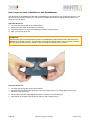
Mounting instructions
The MultiSensor-Door / -RACK-MINI is equipped with several different sensors. To ensure the best
evaluation and functioning of the sensors, please note the following mounting instructions:
• Only install the MultiSensor in horizontal or vertical direction on the handle‘s side of the door or window
CORRECT
WRONG
Magnet
CORRECT
WRONG
• when using the reed contact, keep the distance to the magnet below one centimeter
• only use suitable mounting material (foam tape)
• sensor casing can be fastened with screws on the door or window, if necessary
ATTENTION!
Kentix is not liable for false alarming or damages on devices due to improper installation.
Page 32
!
!
!
!
(08-2014, subject to change)
kentix.de
Usage of the reed contact
The reed contact extends the MultiSensor-Door / -RACK-MINI by an additional alarm contact for the definite
open/closed detection of a door or window. The contact reacts to magnetic fields (magnet contained in
package). For the installation a wiring is not necessary.
To ensure the functionality of the contact, take care to not exceed the maximum distance of one
centimeter between magnet and casing and orientated to one side of the casing of the MultiSensor.
Depending on the type of the door or window it might be necessary to place a spacer between surface and
magnet to not exceed the maximum distance to the sensor.
Page 33
!
!
!
!
(08-2014, subject to change)
kentix.de
Opening of the casing / replacement of battery
The board of the MultiSensor-Door / -RACK-MINI is fixed in the lid of the casing which is connected to the
bottom part with two screws. To open the casing remove the two screws on the top and bottom side and pull
the lid away from the bottom part.
Take the battery out of the mounting and replace it with an equivalent type (see data sheet).
NOTE!
The battery level of the MultiSensor-Door can be read out with the ControlCenter. At a low battery level an
alarm is sent via SMS and E-mail to all administrators. In this case replace the battery as soon as possible.
Adding a MultiSensor-Door / -RACK-MINI
1. For adding a MultiSensor-Door / -RACK-MINI to the AlarmManager‘s configuration, start the teach-in
process in the Kentix ControlCenter. Press the „learn button“ and keep it pressed.
Directly after pressing it, a sound is played which is repeated after approx. 5 seconds.
Release the button after the second sound.
2. The sensor should appear in the list after approx. 15-20 seconds and is configured automatically.
3. The teach-in process is completed, when the sensor is marked in the list with a green checkmark.
4. For completion click on Apply to add the MultiSensor-Door to the devices list.
NOTE!
The MultiSensor-Door (battery version) sends its data, depending on the configured energy profile, in a
routine message every 5 or 10 minutes. Note that it can take up to 10 minutes after saving the data to the
AlarmManager, until the sensors measured values appear in the ControlCenter‘s dashboard.
Identifying a MultiSensor-Door / -RACK-MINI
If more than one sensor was added during the teach-in process, it might be necessary to identify the sensors
for configuration.
To identify a sensor open the settings tab „Sensors-Devices“ and right-click on one of the MultiSensor-Door /
-RACK-MINI. In the context menu choose „Identify sensor“.
A search window appears to display an identified sensor.
Now take one of the sensors and briefly press the „learn button“ one time. The sensor makes a short sound
and will appear in the window after a few seconds.
Afterwards the window closes automatically and the sensor is marked in the device list of the ControlCenter
for further configuration.
Repeat this process for all other MultiSensors, if necessary.
Page 34
!
!
!
!
(08-2014, subject to change)
kentix.de
Profile description
The MultiSensor-Door / -RACK-MINI is configured for its intended use with the help of so called door-profiles
and an associated sensitivity. With these two options the threshold values of the sensor are defined.
Choose the door-profile, which most likely corresponds to the intended use.
Find an overview of the sensitivity levels in the table below:
Sensitivity level
Alarm triggering
Low
The threshold values of the sensor are high. A heavy vibration, acceleration or change in position with an
angle of more than 30 degrees is required to trigger an alarm.
This level is suitable for monitoring the outer skin of a building. The level is unsusceptible for false alarms,
but reliably detects intrusion attempts with the use of force.
Medium
The threshold values of the sensor are on a medium setting. Slight vibrations, accelerations or changes in
position with an angle of more than 10 degrees will trigger an alarm.
This is the default level when adding a new sensor. It is slightly susceptible for false alarms, but offers a
high degree of security by an early alarm triggering.
High
The threshold values of the sensor are on a low setting. Very slight vibrations, accelerations or changes in
position with an angle of more than 5 degrees trigger an alarm.
This level is especially suitable for secured areas. It should only be selected, if the surrounding area is
free of vibration. Slight vibrations in the installation area of the sensor already lead to an alarm triggering
and can so also lead to false alarms.
Testing the settings
To test the profile settings and sensitivity levels, proceed like described in the following:
1. Activate the internal buzzer of the MultiSensor-Door / -RACK-MINI by setting the sensors state in its
configuration mask to „Active (with buzzer)“. This will give an additional acoustic feedback by the sensor
when an alarm is triggered.
2. In the configuration mask of the sensor select „Test mode“ as energy profile. This will reduce the default
send time from 5 minutes to 10 seconds (MultiSensor-Door only).
3. Create a new alarm zone for the sensor and then transfer the settings to the AlarmManager.
4. Switch the zone with the single sensor to armed state.
NOTE! (MultiSensor-Door only)
To save energy the sensor sends its data in normal operation mode (system disarmed) only every 5 minutes
to the AlarmManager. The arming and alarm triggering also is done after data transmission to the
AlarmManager.
Because of this it takes up to 5 minutes until the MultiSensor-Door can trigger alarms.
To avoid this delay, simply press the „learn button“ one time after arming the zone.
5. It is now possible to trigger alarms by moving the door or window.
Note that it takes 30 seconds after an alarm triggering until the next alarm will be triggered.
6. Note that the test mode causes a higher power consumption. To avoid this reset the energy profile to
„Standard“ or „Powersaving“.
Page 35
!
!
!
!
(08-2014, subject to change)
kentix.de
MultiSensor-Rack
The MultiSensor-RACK can be operated as stand alone device, but also in combination with an
AlarmManager-PRO. The AlarmManager then controls the environmental sensors.
For configuration in stand alone operation a web server is integrated, which allows you to control and setup
the device via LAN and a web browser.
Over the SNMP interface, an integration in network management systems is possible.
Safety note and installation
In case of a power failure, the settings are not lost. Energized relays drop out and go back when the power
returns to the unswitched, closed output state.
To bridge longer downtimes, use a suitable UPS system.
In case of an equipment failure an uninterruptible power supply to the connected devices is ensured by the
closed state of the relays.
To ensure the security and integrity of the operator and the correct operation of the KENTIX MultiSensorRACK, the execution of the installation only has to be done by an expert. Also ensure that the relevant
requirements are met.
Connection via PC:!
!
!
!
!
!
!
!
!
!
Connect the LAN jack from the MultiSensor-RACK over a LAN cable with your
network and your PC. Pay attention that you have to use a Cross-Over network
cable, by a direct connection.
Set the IP address of your PC to e.g. „192.168.100.123“.
Default settings
Voltage supply:!!
Default IP-address: !
Subnet mask:! !
Gateway:!
!
User:! !
!
Password:!
!
Basic voltage supply realized with PDU-1 power input
192.168.100.223
255.255.255.0
192.168.100.1
admin
password
Important! Resetting the IP address
If you have forgotten the login information of the MultiSensor-RACK, connect the sensor with a crossovercable/adapter to the Ethernet port of your PC. Start the Kentix ControlCenter and enter the network settings.
Eventually deactivate Firewalls and additional network cards. After a short time the sensor will appear in the
lower section of the network dialogue.
Page 36
!
!
!
!
(08-2014, subject to change)
kentix.de
sc
ro
l
cro l ba
ck
ll f
o
r
Sy
wa
ste
rd
m
sta
te
Di
sp
la
Di
sp
lay
D
OL
E
nti
xS
Ke
ys
Di
sp
lay
r
ys k-Po
tem
rt
xS
ys -jack
tem
1
-j a
ck
2
tw
o
Ke
nti
Ne
Re
se
t-B
utt
on
Overview connections
PDU-1 (Main PDU)
• Independent of PDU-2
• Max. power consumption 3.600VA
• Internal protection 2x10A, time lag fuse
• Total load over all 4 outputs max. 16A
• Power Strip switchable
• Energy measurement outlet 1-4
• Main equipment supply - Electronics
PDU-2
• Independent of PDU-1
• Max. power consumption 3.600VA
• Internal protection 2x10A, time lag fuse
• Total load over all 4 outputs max. 16A
• Power Strip switchable
• Energy measurement outlet 1-4
PDU-2
UPS-Mains connection
(Type C20)
PDU-1
UPS-Mains connection
(Type C20)
PDU-1, Output 1
Power outlet 1+2
(Type C13, 2.300VA/10A)
PDU-1, Output 2
Power outlet 3+4
(Type C13, 2.300VA/10A)
PDU-2, Output 2
PDU-2, Output 1
Power outlet 3+4
Power outlet 1+2
(Type C13, 2.300VA/10A) (Type C13, 2.300VA/10A)
Recommended installation
Installation to front or back
support rail
Page 37
!
!
!
!
(08-2014, subject to change)
kentix.de
1. If possible, install the MultiSensor-RACK at the top position in the
rack and leave 1 height unit free below the device.
This ensures that the environment sensors can detect the actual
state in the rack.
2. For the installation of the mounting brackets only use the included
screws. The mounting brackets can be attached to two different
positions for installation either to the front or to the back support
rail.
3. Connect the power cable of the power consumers to
PDU 1 or 2 and secure them with the provided strain relief.
ConfigurationConfiguration
In the following the stand alone functionality of the integrated web servers is described. For these functions
no AlarmManager is required. If you use the MultiSensor-RACK in combination with an AlarmManager-PRO,
configuration and monitoring of the environment sensors is done via the AlarmManager. The energy
measurement and its alarming states are exclusively found in the web interface.
Important!
The MultiSensor-RACK extends the MultiSensor-LAN by the energy measurement functions. The
MultiSensor functionality corresponds the functionality of the MultiSensor-LAN except for the motion sensor.
To configure MultiSensor settings, read the according section in the MultiSensor-LAN configuration.
Navigation
Dashboard!
!
!
Login! !
Configuration!
System!!
Help ! !
Logout! !
!
!
!
!
!
!
!
- Start page with environment sensors, Energy measurement,
Control of the digital Output 2 and PDU 1+2, Logbook
- User login
- Basic configuration, MultiSensor- / EnergySensor- and User-configuration
- System information (software version), test features, logbook and device-restart
- Manual download and support information
- User logout
Page 38
!
!
!
!
(08-2014, subject to change)
kentix.de
EnergySensor - Energy
Shows all actual energy measurement values for PDU 1+2 (PDU=Power Distribution Unit), the energy
consumption with costs and the alarm state in one table.
Voltage
Display of the actual mains voltage in volt (V).
Flicker
Display of voltage drops of the supply voltage over a configured period of time (number of half-waves,
minimum 1 half-wave) for each PDU as time value / time. Always the last appearance of a voltage drop will
be displayed.
Swell
Display of voltage overshoots of the supply voltage over a configured period of time (number of half-waves)
for each PDU as time value / time. Always the last appearance of a voltage drop will be displayed.
Peak
The MultiSensor-RACK measures the supply voltage with a sampling rate of 4000 measurements / second
(250 µs per measure). A peak is the highest value per second.
Overshoots of the line voltages configured tolerance range in volt with the time of the appearance are
displayed in the table (last appearance of a peak).
Current
Display of the actual power demand of the connected power consumers in ampere (A).
Frequency
Actual mains frequency in hertz (Hz).
The frequency determines the length of the half-waves (50 Hz ≙ 10 ms, 60 Hz ≙ 8,33 ms).
Page 39
!
!
!
!
(08-2014, subject to change)
kentix.de
Active power
The active power (P) shows the actual power of the PDU. Its calculated by multiplying voltage, current and
the power factor.
Apparent power
Total power of the PDU in volt ampere (VA). It results from the idle power and the active power.
Power factor
The power factor is the ratio between active power and apparent power. It indicates which part of the
apparent power is converted to the desired active power.
Energy consumption
Total energy consumption in kilowatt hours (kWh) since the start of the measurement. The consumption
values are stored in the MultiSensor-RACK and preserved even after a restart.
It can be reset in the configurations menu in the EnergySensor section.
Energy costs
Shows the actual costs for the energy consumption since the start of the measurement. The costs result
from the consumption and the configured price.
IMPORTANT!
To display the costs a price has to be entered in the configuration (section EnergySensor).
Output 1/2
Shows the actual state of the outputs (1 output per PDU on MultiSensor-RACK Revision 1, 2 outputs
Revision 2) for the PDUs power supplement of the end devices.
Reset alarms
Resets the display of Flicker-, Swell- and Peak-Alarms.
NOTE!
For actualization of the alarms Flicker, Swell and Peak a Retrigger time is configured which also avoids that
alarms are reported multiple times.
For the actualization / signalization of new alarms resetting the last alarms is not necessary.
Page 40
!
!
!
!
(08-2014, subject to change)
kentix.de
EnergySensor - Monitoring
Graphical display of the recorded active power and energy consumption and costs.
The recording is stored for up to 1 year. If the memory of the recording is full, the oldest values will be
deleted automatically.
The real time graph shows the actual voltage profile, current and peak voltage for the last minute. Peak
alarms will also be displayed. An occurring peak alarm will also be stored for later viewing.
Page 41
!
!
!
!
(08-2014, subject to change)
kentix.de
Control
Switch alarm output 2
Changes the state of the 2nd alarm output (output 1 is controlled by the alarming) for the entered switching
time. If „0“ is entered for the time, the output stays permanently switched on.
For switching, the user password has to be entered. Default state of the output is 0.
PDU 1/2 - Switch outputs
Switches output 1/2 of the PDU on or off. If the value for the switching time is „0“ or empty, the PDU is
switched permanently. For switching, the user password has to be entered.
WARNING!
Deactivating an output stops the power supply to all connected end-devices of the PDU.
Page 42
!
!
!
!
(08-2014, subject to change)
kentix.de
Configuration - EnergySensor
With the following settings set the limits for the alarm triggering of the energy sensors. If an alarm is
triggered, e-mails will be sent to the configured users and the buzzer is activated.
The configuration has to be made for each PDU.
Name
Assign the displayed name for each PDU.
On an alarm the name will also be shown in the notification (e-mail / SMS).
Line voltage / frequency
Sets the regional dependent default values for the external power supplement. This are also the base values
for the error detection and the energy measurement.
Active power / Voltage / Current
Define a minimum and maximum value for each measured value to monitor the energy measurement.
The minimum values are set to 0 in delivery state. After commissioning and configuration the value range
can be redefined to detect e.g the power failure of an end-device. Find the exact limits for each value in the
data-sheet.
Frequency
Enter a limit as tolerance for an fluctuation of the power frequency.
Reference value is 50 Hz or 60 Hz. Adjustment range is 0,1 bis 1,0 Hz (Default value: 0,1 Hz).
Flicker / Swell / Peak
Flicker and Swell are short-term fluctuations of the supply voltage.
Flicker here is a voltage drop, Swell a voltage overshoot.
For the monitoring of both values a tolerance in percent (related to the nominal voltage) and the number of
half-waves to view has to be set.
Peak
Peak is the highest occurring voltage during the normal operation (amplitude).
For the monitoring an upper threshold value of this amplitude voltage can be set. This exceeding is also
called peak or peak-alarm (default value: 400V).
Page 43
!
!
!
!
(08-2014, subject to change)
kentix.de
Alarm handling
The Retrigger time defines, after which time the alarms Flicker, Swell or Peak are reset for the next
triggering. This setting avoids that an event which persists for a longer period will lead to a repeated alarming
in short distances of time.
Costs
Value for the costs per kilowatt hour and the monetary unit.
Reset energy consumption
Sets the internal consumption counter of the MultiSensor-RACK back to 0 and deletes all recorded data.
For safety reasons the user password has to be entered before the reset.
Users
Enter data for up to 5 users with individual passwords. The passwords also give access to the switching
function of the PDUs and the digital output 2.
The account data of the first user are in addition the account data of the internal ftp-server for running
updates on the MultiSensor-RACK. For E-Mail alarming enter the addresses of the recipients here.
System
System information
Shows the firmware version numbers of the MultiSensor-RACK.
Find the actual firmware on the Kentix Website in the Software section.
Test functions
Test your E-Mail and SNMP settings via the two test buttons. The E-Mail or Trap sending is logged and can
be checked in the logbook.
Backup configuration
For backup purposes the actual configuration of the MultiSensor can be downloaded to the PC.
Restore configuration
Loads a previously created backup into the device and restarts it. The settings of the backup directly get
active afterwards.
Firmware-Update
Loads a firmware file (image.bin) into the MultiSensor and restarts it.
ATTENTION!
Please note the corresponding release notes of the downloaded update!
Restart
The MultiSensor-RACK can be restarted for testing- or maintenance purposes. Note that the data recording
is suspended for the duration of the restart. The power supply of the connected devices is NOT interrupted
during the restart.
Page 44
!
!
!
!
(08-2014, subject to change)
kentix.de
Configuration of the vibration sensor
Define the triggering threshold for the integrated vibration sensor. The alarm is triggered, when the threshold
is exceeded.
The trigger sensitivity can be adjusted to detect slight vibrations (e.g. moving of the rack) as well as heavy
vibrations (bumps or movement of the MultiSensor-RACK) can be detected.
Kentix-System-jacks at the MultiSensor-RACK
With the two Kentix-System-jacks on the front of the MultiSensor-RACK external components like e.g. UPS
or leakage sensors can forward an alarm to the MultiSensor. Additionally two Open Collector outputs are
available, 1 for alarming and 1 for remote switching.
For the alarm inputs prefabricated leakage sensors or special adapters (KIO1) are available for connection.
Figure: PIN assignment of the Kentix System-jack
!
Kentix system jack
1 - GND
2 - Alarm output (Open Collector 100mA)
3 - Remote switch output (Open Collector 100mA)
4 - not connected
5 - not connected
6 - External alarm input (External dry contact, no/nc)
7 - External alarm input 2 (External dry contact, no/nc, Default configured as sabotage input)
8 - 5V internal system voltage
IMPORTANT!
The switching outputs 6/7 are open collector transistor outputs and the maximum load is 100mA.
The switching output 1 is automatically switched by an alarm (Armed-Active or Always-Active) trigger.
The switching output 6 in standalone mode can only be activated via the SNMP or SMS remote function.
In AlarmManager mode the output can be used for arm/disarm signalization.
The alarm inputs can be wired via the Kentix Power Adapter (KIO1) with potential free contacts.
!
!
Page 45
Figure: Kentix Power Adapter (KIO1)
!
!
!
!
(08-2014, subject to change)
kentix.de
Control a network camera with MultiSensor-LAN/RACK
The MultiSensor-RACK offers the possibility to send a control sequence as a HTTP request to any IP ready
network camera in case of an alarm. So in addition to the e-mail alerting also a video picture or a video
sequence can be sent. The transmission from the video picture is done by the camera.
The information to control the camera has to be inserted into the „cam.ini“ file. Create this file with a text
editor and copy it to the root directory of the MultiSensor via FTP, where you will also find the „config.ini“ file.
After a reboot the configured command sequence will be sent to the camera in case of an alarm. Up to five
cameras can be controlled. Create a new line in the „cam.ini“ file for each camera.
File content (cam.ini)
IP-ADDRESS;IP-PORT;HTTP-CAM-COMMAND;HOST-ADDRESS;SERVER-NAME
The delimiter for each parameter is a semicolon.
EXAMPLE: File content (cam.ini)
192.168.100.224;80;/cam/command/input=trigger;www.kentix.de;My-Camera
The HOST address can be any, is required by some camera servers.
EXAMPLE: File content (cam.ini) for AXIS Video Server 240
192.168.100.224;80;/axis-cgi/io/virtualinput.cgi?action=6:/;www.kentix.de;Axis-Server240
Details for configuring E-Mail events in your network camera and the control sequence can be found
in the manual of the camera manufacturer.
Communication Interfaces MultiSensor-LAN/RACK
With the MultiSensor-RACK it is possible to send alarms as SNMP Traps.
Additionally all sensor values can be queried using the supplied MIB (Management Information Base).
This allows the integration in network-monitoring-systems like e.g. PRTG or Nagios.
For querying values and also recorded environment- and consumption values the MultiSensor-RACK
furthermore has a XML interface. The following queries can be executed:
XML-Path
Description
http://IP-Address/xml/values.xml
The actual environment values
http://IP-Address/xml/energy.xml
The actual energy measurement values split by PDU 1+2
http://IP-Address/xml/record_values.xml
Recorded environment values of the last 3 month
http://IP-Address/xml/record_energy.xml
Recorded average power per 15 minutes for a timespan of up
to 1 year
Page 46
!
!
!
!
(08-2014, subject to change)
kentix.de
Perform software updates on MultiSensor-LAN/RACK
The MultiSensor-LAN/RACK offers the possibility to actualize its software via the integrated FTP-server.
Actual software updates are available in the software section on www.kentix.de.
To check the actual installed software version, open the sensor‘s web server and open the system
information in the „System“ section.
To perform an update follow these steps:
Nr
Step
1
Ensure that the internal FTP-Server of the MultiSensor is activated. It is activated by default, but can be
reactivated in the „Configuration“ section of the web interface, if necessary.
2
Unpack the update file (ZIP) into an new folder on your PC. The unpacked file has the name „image.bin“ and
must not be renamed.
3
Connect to the MultiSensor via FTP-Client (e.g. FileZilla). To log in enter the user data of the first user
(default: admin/password).
4
Download the files „config.ini“ (LAN+RACK) and „config_e.ini“ (RACK only) from the MultiSensor to back up
your configuration.
5
Now upload the file „image.bin“ into the root directory of the MultiSensor.
6
After about 1-2 minutes the MultiSensor automatically restarts.
IMPORTANT! During the update process, the power supply must not be interrupted.
7
The MultiSensor is now available again and you can check the software version in the „System“ section.
This can take up to 2 minutes after the first start.
8
Connect again with the FTP-Client to upload the stored configuration.
Perform a restart via the web interface afterwards to load the configuration.
Backup or copy configuration from MultiSensor-LAN/RACK
Nr
Step
1
Ensure that the internal FTP-Server of the MultiSensor is activated. It is activated by default, but can be
reactivated in the „Configuration“ section of the web interface, if necessary.
2
Connect to the MultiSensor via FTP-Client (e.g. FileZilla). To log in enter the user data of the first user
(default: admin/password).
3
Download the files „config.ini“ (LAN+RACK) and „config_e.ini“ (RACK only) from the MultiSensor to back up
your configuration.
4
To transfer the configuration onto another MultiSensor, simply copy the file(s) to the desired sensor and
restart it. Note that the 2nd sensor will afterwards have the same IP address as the first one. It is possible to
alter the address with a text editor before uploading.
Note!
From firmware version 4.00.00 on the update via FTP-Server is obsolete.
In future, updates as well as Backup and Restore of the configuration are preformed via the web interface
of MultiSensor-LAN/RACK.
Detailed information for the update procedure with a new firmware can always be found in the release
notes coming with the corresponding update.
Page 47
!
!
!
!
(08-2014, subject to change)
kentix.de
How to open the case of MultiSensor and AlarmManager
The device lids of the MultiSensor-RF/LAN or AlarmManager are jammed in one surrounding groove on the
device bottom part with the electronics. The lid can be lifted without tools by slightly pulling it apart on its
sides. Proceed as follow:
Open the device lid:
1. Lay down the device with the port side forward.
2. Pull the lid at the sides apart sightly (see picture).
3. The lid will snap out from the surrounding groove with a clicking noise.
4. Now, you can pull up the lid.
ATTENTION!
The PIR motion sensor and temperature sensor in the MultiSensor-RF/LAN are fixed to the board of the
MultiSensor via a plug connector. It is important to open the lid with the motion sensor carefully to the left
side after pulling it down from the rabbet, to avoid harming the cabling or the connector.
Close the device lid:
1. Lay down the device with the port side forward.
2. Pay attention, that the broader protrusion from the lid (space groove to casing edge) shows in the
direction of the connectors.
3. Pull the lid by the sides apart slightly and put the casing lid on the bottom part.
4. Slide the lid on the bottom part till the lid snaps in with a clicking sound.
Page 48
!
!
!
!
(08-2014, subject to change)
kentix.de
KeyPad
The KeyPad is used for arm-disarm switching of the AlarmManager on the ground. The KeyPad is just like
the MultiSensors integrated into the ZigBee© wireless network of the AlarmManager. However, note that the
KeyPad does not work as a router and can not extend the network range.
Note that the KeyPad turns on only after pressing one of the three function keys.
The duty cycle is then about 10 seconds. During this time you can select appropriate functions or
communicate with the ControlCenter.
RF learn button
RFID reader (Legic® or Mifare®)
Optional, depending on type.
Adding a KeyPad
1. For adding a KeyPad to the AlarmManagers configuration start the teach-in process in the Kentix
ControlCenter. Press one of the function buttons and then the „learn button“.
2. Now press one of the function buttons for every 5 seconds. The KeyPad should appear in the list during
the next 15-20 seconds and will be configured automatically.
3. The teach-in process is finished when the KeyPad is marked in the list with a green checkmark.
4. To add the KeyPad to the devices list, click on Apply.
Page 49
!
!
!
!
(08-2014, subject to change)
kentix.de
Operation KeyPad
First press the desired function key (arm, disarm, zone) and then enter your personal 4-digit code. The
function is triggered immediately after entering the fourth and last code digit. Each key-press is
acknowledged with an acoustic "beep". The selected function is indicated by an LED in the button.
By pressing one of the keys "arming" or "disarming" followed by entering your
personal code the zone assigned to the KeyPad is switched.
Note that every user needs the according permissions to use a KeyPad.
If you would like to arm-disarm the whole system (all zones), first press the zone
button and then button 1. Then run the desired function of the function key.
The LEDs are blinking according to the possible entries.
Basically for the KeyPad operation it is the same acoustic and optical feedback, such as for remote control
via mobile phone or an external switch contact.
Arming - leave the room
OK :
5 seconds acoustic beep signal, LED lights constant, MultiSensors signal acoustically
according to the time delay.
Not OK :
3 seconds constant acoustical signal. All LEDs are flashing.
Switch all zones
Controlled by pressing the zone button followed by button 1. After it the LEDs for the
possible functions for arm or disarm light up.
Disarming - enter the room
OK :
1 second constant acoustic signal, LED lights constant, MultiSensors signal also with 1
second acoustic signal.
RFID reader (Optional)
Select the desired function (arm, disarm, zone) and keep the RFID card centered on
the reader. The function is executed immediately after the correct read.
Important!
With the KeyPad only alarms of the type „Armed-Active“ can be switched to armed-disarmed.
Alarms of the type „Always-Active“ are triggered independent of the armed-disarmed state of the
AlarmManager. The sensors can be assigned individually to the two alarm levels.
Page 50
!
!
!
!
(08-2014, subject to change)
kentix.de
Enhancements
With the Alarm inputs at the terminal blocks or the system jacks of AlarmManager and MultiSensor it is
possible to connect external components like door-contacts or leakage-sensors.
In the following you see connection examples for the leakage-sensor available at Kentix.
Leakage-sensor
The leakage-sensor is already prepared with a RJ45-connector for Kentix devices.
Powering is also realized via this connector. A LED inside its case signals the actual state of the sensor
(green: no alert / no humidity; red: alert / humidity detected). To test functionality, touch the bottom of the
sensor with a slightly wetted cloth).
IMPORTANT!
The signaling for a connected leakage-sensor is realized via the external alarm input of the device to which
the leakage-sensor is connected (AlarmManager or MultiSensor). For the correct functioning, this input has
to be configured correctly (see examples).
Therefor its necessary to test the alert triggering after connection to ensure the correct cabling.
Connection example 1: Leakage-Sensor connected to AlarmManager
AlarmManager-BASIC/PRO
Leakage-sensor
KENTIX System-jack
Plug the connection cable of the leakage-sensor into one of the System-jacks of the AlarmManager.
The powering and alarming is done directly via the AlarmManager. With the ControlCenter enter a suitable
name for the external alarm input and set the alarming of the input to „Always-Active“ for a permanent
alarming. If the leakage sensor is working with opening the contact on an alarm, additionally change the
alarm logic to „Open“.
Page 51
!
!
!
!
(08-2014, subject to change)
kentix.de
Connection example 2: Leakage-sensor connected to MultiSensor
MultiSensor-RF/LAN
KENTIX Power-Adapter
Leakage-Sensor
KENTIX System-jack
Plug the connection cable of the leakage-sensor into one of the jacks of the Kentix Power-Adapter (KIO1).
Connect the MultiSensor to the Power-Adapter with the modular cable (sent with the Power-Adapter).
Connect the delivered power supply to the Power-Adapter for currency.
The powering of leakage-sensor and MultiSensor is realized via the Power-Adapter, the alarming via the
external input of the MultiSensor.
With the ControlCenter enter a suitable name for the external alarm input and set the alarming of the input to
„Always-Active“ for a permanent alarming. If the leakage sensor is working with opening the contact on an
alarm, additionally change the alarm logic to „Open“.
NOTE!
Using the leakage sensor together with a MultiSensor a fully wired patch cable is required for the
connection between MultiSensor and power adapter.
Page 52
!
!
!
!
(08-2014, subject to change)
kentix.de
Kentix Power-Adapter (KIO1)
The Kentix I/O Power-Adapter is used to expand your Kentix-solution to include additional components.
With the Adapter it‘s possible to supply power to 2 additional devices. Depending on your requirements the
alarm via the external inputs can be activated or deactivated.
Figure 1 shows the back of a Power-Adapter with the jumpers set (extraditable state) e.g. to use it with a
leakage-sensor. When connecting 2 MultiSensors remove both jumpers to avoid fail alarming or double
alarms.
Additionally the alarm inputs of System-jack 1 are available at the terminal of the adapter (figures 1+2).
Figure 1: Back of Kentix Power-Adapter (KIO1)
Figure 2: Circuit diagram
Page 53
!
!
!
!
(08-2014, subject to change)
kentix.de
Kentix IO-Modules
The AlarmManager-PRO can be extended by additional digital Inputs and Outputs via special Expansion
modules. For this 2 external modules (KIO7052 with 8 digital Inputs / Outputs and KIO7053 with 16 digital
Inputs) are available.
Both modules are configured via a Web browser and are queried by the AlarmManager over the network.
Commissioning and Configuration
Depending on the module type it can be powered via PoE or with an external power supply. Using a power
supply it is necessary to regard the information in the data sheet, or only to use a power supply delivered by
Kentix. Information for the wiring of the In- and Outputs can also be found in the data sheet.
Terminal assignment KIO7052
No
1
2
3
4
Step
Comment
Connect the network port E1 to a network switch with PoE support.
Connect your PC to this switch respectively establish a network
connection.
If you use a switch without PoE establish
power supply via the connectors (R)+Vs and
(B)-GND. Use the supplied power adaptercable
Open the Web-Interface of the module via the default IP 192.168.255.1
and change the IP-settings in „Network Settings“ to your required settings.
Default username and password: Admin/Admin
In the section „Web HMI“ the Inputs and
Outputs of the module can be monitored for
test purposes.
Start the Kentix ControlCenter and open the configuration of the I/Omodule via „Settings“ -> „Advanced...“ -> „External Alarms“
Select the module type and set the configured
IP-address.
Proceed with the setup for the wired external Inputs:
Enter a name for the alarming and choose alarm assignment and the
alarm logic. Eventually enter another alarm delay (default 1 sec.). Also
select an alarm zone for every used input.
In the module KIO7052 for each alarming
state one of the 8 Outputs is switched. Find
the assignment of the Outputs in the data
sheet of the module.
Save the configuration. After this the settings are directly active.
For testing purposes the state of the alarm
inputs can be monitored in the table
„MultiSensor Monitoring“.
5
Page 54
Terminal assignment KIO7053
!
!
!
!
(08-2014, subject to change)
kentix.de
MultiSensor-LAN-RF (LAN-ZigBee Repeater)
The MultiSensor-LAN-RF offers the same functionality as the MultiSensor-LAN.
Moreover it allows the creation of a dedicated radio network. With this option it is possible to realize a
connection to distant RF-Components (MultiSensor-RF / -Door / KeyPads) via LAN/WAN. The configuration
of the repeater and the connected components is done via the Kentix ControlCenter.
If the sensor is added as LAN-RF-Repeater, additional sensors can be added via the context menu (right
mouse button) of the MultiSensor list. In this menu it is also possible to reset the radio network of the
repeater.
AlarmManager-PRO
MultiSensor-LAN-RF
MultiSensor-RF
MultiSensor-Door
KeyPad-RF
MultiSensor-LAN-RF
MultiSensor-RF
MultiSensor-Door
KeyPad-RF
Page 55
!
!
!
!
(08-2014, subject to change)
kentix.de
Kentix AlarmManager Smartphone-App
With the Kentix-App a monitoring and control of a Kentix System via iPhone / iPad or Android devices is
possible. In the following, functions and control of the app are described.
The Profile menu
When starting the app the profile selection menu is displayed.
With the „+“ Button in the upper right edge a new profile is created. To differentiate between multiple devices,
enter a unique name and choose the device type.
Enter IP-address, username and password of the device. The password can optionally be saved. Username
and password correspond to the access data of the web interface.
When the SMS control of the AlarmManager is activated, additional numbers and a PIN can be entered to
switch the system from out of the network.
As starting screen either the Dashboard or the control menu can be selected. To save the profile, press the
according button in the upper right.
AlarmManager
Dashboard
The dashboard shows - as on the web interface - an overview of the AlarmManager.
The controls MultiSensors and Server switch to a detailed view, where the corresponding measurement
values and the state of the devices are displayed.
With „swiping gestures“ or via the selection menu in the upper right it is possible to switch between single
sensors / servers. The selection menu additionally shows the general alarm state of all devices.
Control
The control menu displays the list of the AlarmManager‘s alarm zones.
Alarm zones, which the user is not allowed to switch, are greyed out in the overview.
For switching press the desired entry and choose a command in the selection menu.
Logbook
Pressing one of the entries opens a detailed view. By selecting a filter the logbook can be sorted by different
message types (e.g. alarms or system messages).
Page 56
!
!
!
!
(08-2014, subject to change)
kentix.de
SMS Control
When the AlarmManager cannot be accessed via the local network, it can be switched via SMS commands.
Trying to access without network connection, the app automatically starts into the corresponding menu,
when a telephone number for the AlarmManager is entered in the profile.
Before sending the SMS-text the message has to be confirmed.
MultiSensor-LAN / -LAN-RF / -RACK
To control a MultiSensor-LAN or MultiSensor-RACK in standalone mode connect to it via a profile - as
described for the AlarmManager. The device type must be set to „MultiSensor“.
After connecting an overview of the sensors measured values is displayed.
The button „Motion detection“ switches the arm/disarm state of the MultiSensor.
Via the button „Alarm output 2“ the 2nd digital output of the MultiSensor can be activated for 30 seconds.
Note:
After an alarm was triggered the device can first be rearmed again after 1 minute.
For the switching functions (motion / digital output) the AlarmManager-communication in the MultiSensor
must be inactive.
Page 57
!
!
!
!
(08-2014, subject to change)
kentix.de
Data sheets
Data sheet AlarmManager-BASIC/PRO (KAM-BASIC/PRO)
Number of MultiSensor (KAM-BASIC)
Number of MultiSensor (KAM-PRO)
Max 10 pc MultiSensor-RF
Max 100 pc MultiSensor-RF / -LAN / -RACK
/ -DOOR / -RACK-MINI
Number of KeyPad (KAM-BASIC)
Number of KeyPad (KAM-PRO)
Max 3 pc KeyPad connectable
Max 100 pc KeyPad connectable
Internal Buzzer
85dB, 2.3kHz
Ext. alarm inputs
1 x alarm input (Armed-Active, Always-Active)
1 x external arm/disarm
Both for external potential-free contacts
Ext. relay outputs
2 x relay with alt. contact (Armed-Active, Always-Active)
max contact power: 125VAC/60VA, 60VDC/25W
Internal temper sensor
Internal vibration sensor (high sensitive)
LED
RUN (yellow)
GSM (yellow)
ALARM (red)
ARMED (red)
Radio
ZigBee® 2,4GHz ISM Band +3dBm output power,
IEEE802.15.4, encryption AES 128 Bit
LAN
10/100Mbit
Integrated GSM Modem
Quad Band (GSM/GPRS) 850/900/1800/1900MHz
integrated SIM card holder
Power supply
10-32VAC/DC power consumption ca 2W
Integrated UPS
4 minutes up time by internal high capacitor.
Control of external power supply.
Kentix system jack
2 pc. RJ45, for external plug´n play modules (KIO1,
KIO2, KPS,...)
Chassis
Material: PS 130 x 90 x 45 mm
Weight approx. 300g
Color: High-White, Carbon-Black
Environmental conditions
Temperature 0 - 45°C / 32 - 113°F
Humidity 5-95%, not condensing
Types
KAM-BASIC-B = Chassis carbon black
KAM-BASIC-W = Chassis high white
Content of delivery
Plug power supply 100-230VAC/24VDC, 12Watt
2 pc of antennas (ZigBee, GSM)
PowerAdapter, mounting bracket and material
Accessories
Leakage sensor (KLS02P)
External Antennas for ZigBee and GSM
Approvals
CE
Page 58
!
!
!
!
(08-2014, subject to change)
kentix.de
Data sheet MultiSensor-RF (KMS-RF)
Connectable devices
AlarmManager-BASIC (KAM-BASIC)
AlarmManager-PRO (KAM-PRO)
Sensor - temperature
range -20 to 99°C / -3 to 210°F (exactness ± 0,5°)
Sensor - relative humidity
range 0 to 100% (exactness ± 3%)
Dew point
calculated in °C/°F
Sensor - motion
PIR sensor, adjustable responsivity
detection cone: 100°
range: approx. 8m
Sensor - vibration
3 axes vibration sensor (adjustable)
Sensor - carbon monoxide (CO)
0-10.000ppm measurement ± 10%
Internal resolution: 20-200ppm (0-100%)
lifetime approx. 5 years
Buzzer
85dB, 2.3kHz
Sensor - external alarm input
1 x alarm input (Armed-Active, Always-Active)
1 x sabotage input
Both for external dry contacts
Ext. output
2 x open collector 0.1A/12V (alarming, remote
switching)
LED
ALARM (red)
RUN (green)
Radio
ZigBee® 2,4GHz ISM band +3dBm output power,
IEEE802.15.4, encryption AES 128 Bit
Power supply
12-32VAC/DC power consumption. ca 0.5W
Integrated UPS
4 minutes up time by internal high capacitor.
Control of external power supply.
Kentix System-jack
RJ45, for external plug´n play modules (KIO1, KIO2,
KPS,...)
Chassis
Material: PS 90 x 90 x 45 mm
Wight: approx. 100g
Color: High White, Carbon Black
Environmental conditions
Temperature 0 - 45°C / 32 - 113°F
Humidity 5-95%, not condensing
Types
KMS-RF-B/W
B = Chassis Carbon-Black
W = Chassis High-White
Content of delivery
Mounting bracket and material
Accessories
PowerAdapter (KIO1)
Plug power supply with 6m modular cable (KOP)
Leakage sensor (KLS02P)
Approvals
CE
Page 59
!
!
!
!
(08-2014, subject to change)
kentix.de
Data sheet MultiSensor-LAN (KMS-LAN)
Connectable devices
Stand-Alone operation (integrated web server)
AlarmManager-PRO
Sensor - temperature
range -20 to 99°C / -3 to 210°F (exactness ± 0,5°)
Sensor - Relative humidity
range 0 to 100% (exactness ± 3%)
Dew point
calculated in °C/°F
Sensor - motion
PIR sensor, trigger sensitivity configurable
detection cone: approx. 100°
range: approx. 8m
Sensor - vibration
3 axes vibration sensor (adjustable)
Sensor - carbon monoxide (CO)
0-10.000ppm measurement ± 10%
Internal resolution: 20-200ppm (0-100%)
lifetime approx. 5 years
Buzzer
85dB, 2.3kHz
Sensor - external alarm input
1 x alarm input (Armed-Active, Always-Active)
1 x sabotage input
wiring potential free
External alarm output
2 x open collector 0.1A/12V (alarming, remote
switching)
LED
ALARM (red)
RUN (green)
LINK/ACT at the LAN jack
LAN
10/100Mbit LAN connection
integrated web server
SNMP
(Simple Network Management Protocol)
SNMP V2 (write/read)
SNMP Traps
power supply with PoE
12-72VAC/DC power consumption ca. 1.5W
PoE class 1
power supply with power supply unit
12-32VAC/DC power consumption ca. 1.5W over
system jack
KENTIX system jack
RJ45, for external plug´n play modules (KIO1)
Chassis
Material: PS 90 x 90 x 45 mm
Weight approx. 100g
Color: high white, carbon black
Environmental conditions
Temperature 0 - 45°C / 32 - 113°F
Humidity 5-95%, non-condensing
Types
KMS-LAN-B (Chassis Carbon-Black)
KMS-LAN-W (Chassis High-White)
Content of delivery
Mount bracket, Mount material
Accessories
PoE Injector (KPOE150S)
PowerAdapter (KIO1)
Plug power supply with 6m modular cable (KOP)
Leakage sensor (KLS02P)
Approvals
CE
Page 60
!
!
!
!
(08-2014, subject to change)
kentix.de
Data sheet MultiSensor-LAN-RF (KMS-LAN-RF)
Connectable devices
Stand-Alone operation (integrated web server)
AlarmManager-PRO
Sensor - temperature
range -20 to 99°C / -3 to 210°F (exactness ± 0,5°)
Sensor - Relative humidity
range 0 to 100% (exactness ± 3%)
Dew point
calculated in °C/°F
Sensor - motion
PIR sensor, trigger sensitivity configurable
detection cone: approx. 100°
range: approx. 8m
Sensor - vibration
3 axes vibration sensor (adjustable)
Sensor - carbon monoxide (CO)
0-10.000ppm measurement ± 10%
Internal resolution: 20-200ppm (0-100%)
lifetime approx. 5 years
Buzzer
85dB, 2.3kHz
Sensor - external alarm input
1 x alarm input (Armed-Active, Always-Active)
1 x sabotage input
wiring potential free
External alarm output
2 x open collector 0.1A/12V (alarming, remote switching)
LED
ALARM (red), RUN (green)
LINK/ACT at the LAN jack
LAN
10/100Mbit LAN connection
integrated web server
Radio
ZigBee® 2,4GHz ISM band +3dBm output power,
IEEE802.15.4, encryption AES 128 Bit
SNMP (Simple Network Management
Protocol)
SNMP V2 (write/read)
SNMP Traps
power supply with PoE
12-72VAC/DC power consumption ca. 1.5W
PoE class 1
power supply with power supply unit
12-32VAC/DC power consumption ca. 1.5W over system
jack
KENTIX system jack
RJ45, for external plug´n play modules (KIO1)
Chassis
Material: PS 90 x 90 x 45 mm, Weight approx. 100g
Color: high white, carbon black
Environmental conditions
Temperature 0 - 45°C / 32 - 113°F
Humidity 5-95%, non-condensing
Types
KMS-LAN-B (Chassis Carbon-Black)
KMS-LAN-W (Chassis High-White)
Content of delivery
Mount bracket, Mount material
Accessories
PoE Injector (KPOE150S)
Plug power supply (KOP)
Power-Adapter (KIO1)
Leakage sensor (KLS02P)
Approvals
CE
Page 61
!
!
!
!
(08-2014, subject to change)
kentix.de
Data sheet MultiSensor-RACK (KMS-RACK)
Connectable devices
Stand-Alone operation (Integrated Web-Server)
AlarmManager-PRO
Sensor - temperature
range -20 to 99°C / -3 to 210°F (exactness ± 0,5°)
Sensor - Relative humidity
range 0 to 100% (exactness ± 3%)
Dew point
calculated in °C/°F
Sensor - motion
3 axes vibration sensor (adjustable)
Sensor - carbon monoxide (CO)
Fire detection via CO-Sensor
Internal resolution: 20-200ppm (0-100%) adjustable
Sensor-lifetime: 5 years (replaceable)
Buzzer
85dB, 2.3kHz
Sensor - external alarm inputs / outputs
2 Kentix System-jacks (SYS 1/2) to connect external Plug´n Play modules (RJ45)
like door contacts , leakage-sensors, external alarms.
Assignment:
2 x Alarm input (Armed-Active, Always-Active)
2 x Open Collector output 0.1A/12V (1x Alarming, 1x Remote control)
Sensor-Energy measurement
Voltage (V), Current (A), Active Power (W), Apparent power (VAR), Consumption
(kWh), Power factor (%), Consumption total (kWh), Consumption per month (kWh),
Costs (Currency)
Display
OLED Display to display the actual measurement values
LEDs to display ALARMs and RUN
LAN
10/100 Mbit LAN connection (IEEE 802.3)
integrated web-Server
SNMP - Data Interfaces
(Simple Network Management Protocol)
SNMP/V2 (write/read) and SNMP Traps
XML Data-export for measured values
Power supply
100-240VAC, power consumption approx. 4W
Supply of PDU 1+2 with IEC-connector type C20/16A
PDU Connection
(Power Distribution Unit)
2 separate PDU with 4 IEC power outlets (C13/10A) per PDU with strain reliefs
Maximum power consumption 7.200VA with 3.600VA each for PDU-1/2
PDU-1 and PDU-2 separately switchable with timer- and reset-function
Measurement accuracy
(at 20°C ambient temperature)
Voltage (RMS 90-260V)!
Current (RMS 0,002-12A)!
Active power (1.5-2.760W)!
Protection PDU 1/2
4 pcs. 10A micro fuse (5x20mm), time-lag - TH 250V with extinguishant
Casing
IT-Rack 1 HE (44mm), mounting brackets for front and rear
Dimensions: 418 x 165 x 44 mm (B x T x H), weight 1.25kg
Environmental conditions
Temperature 0 - 45°C / 32 - 113°F
Humidity 5-95%, not condensing
Content of delivery
2 pcs. IEC power cable with 3m (Type: C20/C19), 19“ mounting-brackets
Accessories
Leakage sensor (KLS02P)
Power-Adapter (KIO1)
Approvals
CE
Page 62
!
!
!
!
(08-2014, subject to change)
+/- 0,5%
+/- 0,5%
+/- 0,5%
kentix.de
Data sheet MultiSensor-Door (KMS-Door)
Connectable devices
AlarmManager-BASIC (KAM-BASIC)
AlarmManager-PRO (KAM-PRO)
Sensor - temperature
range -20 to 99°C / -3 to 210°F (exactness ± 0,5°)
Sensor - Relative humidity
range 0 to 100% (exactness ± 3%)
Dew point
calculated in °C/°F
Sensor - Acceleration sensor
0-3G, 3 axes, adjustable sensitivity
Sensor - Gyrometre
angular sensitivity adjustable (5-360°, 3 axes)
Buzzer
65dB, 2.3kHz
LED
Multicolor-LED (Red/Green)
ALARM (Red)
Teach-in (Green)
ZigBee® 2,4GHz ISM band +3dBm output power,
IEEE802.15.4, encryption AES 128 Bit
Radio
Power supply
Battery: 1x Lithium Ion 1/2 AA 3,6V (1200 mAh)
Battery life approx. 2 years, depending on energy profile
Chassis
Material: PS 63 x 29 x 28 mm
Weight approx. 50g
Color: high white
Environmental conditions
Temperature 0 - 45°C / 32 - 113°F
Humidity 5-95%, non-condensing
Types
KMS-Door-W (casing High-White)
Accessories
1x Li-Battery 3,6V/1200mAh
Mounting material
Magnet for REED-contact
Approvals
CE
Page 63
!
!
!
!
(08-2014, subject to change)
kentix.de
Data sheet MultiSensor-RACK-MINI (KMS-RACK-MINI)
Connectable devices
AlarmManager-BASIC (KAM-BASIC)
AlarmManager-PRO (KAM-PRO)
Sensor - temperature
range -20 to 99°C / -3 to 210°F (exactness ± 0,5°)
Sensor - Relative humidity
range 0 to 100% (exactness ± 3%)
Dew point
calculated in °C/°F
Sensor - Acceleration sensor
0-3G, 3 axes, adjustable sensitivity
Sensor - Gyrometre
angular sensitivity adjustable (5-360°, 3 axes)
Buzzer
65dB, 2.3kHz
LED
Multicolor-LED (Red/Green)
ALARM (Red)
Teach-in (Green)
Radio
ZigBee® 2,4GHz ISM band +3dBm output power,
IEEE802.15.4, encryption AES 128 Bit
Power supply
USB: USB1.1 / USB2.0 Mini-USB 5V/40mA
Chassis
Material: PS 63 x 29 x 28 mm
Weight approx. 35g
Color: carbon black
Environmental conditions
Temperature 0 - 45°C / 32 - 113°F
Humidity 5-95%, non-condensing
Types
KMS-Door-B (casing Carbon/Black)
Accessories
USB-Connector cable 1,8m
Mounting material
Magnet for REED-contact
Approvals
CE
Page 64
!
!
!
!
(08-2014, subject to change)
kentix.de
Data sheet KeyPad (KKP)
Connectable devices
AlarmManager-BASIC/PRO
MultiSensor-LAN-RF
Buzzer
70dB, 2.3kHz
LED
Zone (RED/GREEN)
Arm (RED/GREEN)
Disarm (RED/GREEN)
Radio
ZigBee® 2,4GHz ISM band +3dBm output power,
IEEE802.15.4, encryption AES 128 Bit
Power supply (battery)
Battery 2 pc. 1.5V/AAA
Battery life approx. 3 years (without RFID)
Battery life approx. 2 years (with RFID)
depending on the number of switching cycles
Chassis
Material: PS 135 x 90 x 19 mm
Weight ca. 100g
Color: High-White
Protection class: IP40
Environmental conditions
Temperature 0 - 45°C / 32 - 113°F
Humidity 5-95%, not condensing
Types
KKP
KKP-LEGIC® (with RFID reader)
KKP-MIFARE® (with RFID reader)
KKP-HITAG® (with RFID reader)
Content of delivery
KKP: Battery
KKP-LEGIC/MIFARE/Hitag: 2 pc. of RFID Token
Accessories
Battery KeyPad 1.5V/AAA, 1000mAh
RFID Token Legic®
RFID Token Mifare®
RFID Token Hitag®
Approvals
CE
Page 65
!
!
!
!
(08-2014, subject to change)
kentix.de
Data sheet digital I/O expansion-module (KIO7052)
Front
Back
Pin assignment KIO7052
Description
Expansion module for connection to the AlarmManager-PRO.
This module extends the external inputs and outputs of AlarmManager
on additional 8 digital inputs and 8 digital outputs. Communication is
via Ethernet, so the module can be mounted anywhere. The
configuration is done in the software interface of the
AlarmManager-PRO. The module provides a build in web-server with
for simple IP configuration and testing of the inputs and outputs
without any additional software.
Connectivity
Connection to Kentix AlarmManager-PRO
External Alarms of existing system equipment
(HVAC, UPS systems, generators, alarm systems, etc.)
Configuration
Build in Web-Server (HTTP), Default IP: 192.168.255.1 (Admin/Admin)
Protocols
KAM-IO communication via IP-PORT: 502 (Default)
Security
ID, Password and IP-Filter
Terminals
Plug-able screw-terminal for cables up to 1mm²
Inputs
Digital wet inputs
ON: +10–50VDC, OFF: +4DC
Input impedance: 10kOHM
Over voltage protection: 70VDC
Outputs
Open-Collector outputs 10–40VDC
Current 650mA (bis 1.1A Over current protection)
Over voltage protection: 47VDC
Fixed output
assignment
DO1-DO8: Armed-Active, Always-Active, Sabotage, General-Alarm,
Arm-Zone1, Arm-Zone2, Arm-Zone3, Arm-General
Isolation
Ethernet 1,5kVDC, I/O 3,7kVrms
Environment
Operation temperature -25°C to +75°C, Rel. humidity 10–90%
Network
LAN 10/100 Base-TX
Power supply
PoE (Class 1) or externes power supply 12–30VDC, 4.3Watt
Chassis
72 x 123 x 35 mm (DIN-rail mounting)
Content of delivery
KIO7052, 3m patch-cable, power-cable, manual
Approvals
CE
Accessories
Power-supply or PoE injector if no PoE supply is available
INPUT sink signal (High=1)
INPUT sink signal (Low=0)
INPUT sink signal (High=1)
Page 66
!
!
!
!
(08-2014, subject to change)
INPUT source signal (Low=0)
OUTPUT relay
OUTPUT sink (resistive)
kentix.de
Data sheet digital I/O expansion-module (KIO7053)
Front
Back
Pin assignment KIO7053
Description
Expansion module for connection to the AlarmManager-PRO.
This module extends the external inputs of the AlarmManager on
additional 16 digital alarm inputs. Communication is via Ethernet, so
the module can be mounted anywhere. The configuration is done in
the software interface of the AlarmManager-PRO. The module
provides a build in web-server with for simple IP configuration and
testing of the inputs and outputs without any additional software.
Connectivity
Connection to Kentix AlarmManager-PRO
External Alarms of existing system equipment
(HVAC, UPS systems, generators, alarm systems, etc.)
Configuration
Build in Web-Server (HTTP), Default IP: 192.168.255.1 (Admin/Admin)
Protocols
KAM-IO communication via IP-PORT: 502 (Default)
Security
ID, Password and IP-Filter
Terminals
Plug-able screw-terminal for cables up to 1mm²
Inputs
Digital dry contacts for potential-free wiring
ON:
Open
OFF: Close to GND
Isolation
Ethernet 1,5kVDC, I/O 3,7kVrms
Environment
Operation temperature -25°C to +75°C, Rel. humidity 10–90%
Network
LAN 10/100 Base-TX
Power supply
PoE (Class 1) or externes power supply 12–30VDC, 4.3Watt
Chassis
72 x 123 x 35 mm (DIN-rail mounting)
Content of delivery
KIO7053, Power supply 24VDC, manual
Approvals
CE
Accessories
Power-supply or PoE injector if no PoE supply is available
Page 67
!
!
!
!
(08-2014, subject to change)
INPUT dry contact (High=1)
INPUT dry contact (Low=0)
kentix.de
Checklist - Acceptance report
After the successful installation, we implicitly recommend to do a function-check of all components, to ensure
the clean operation. Use the following check-list for this.
It can also be used as an acceptance report for the system handover to the customer.
IMPORTANT!
To ensure full functionality, we recommend to repeat this check periodically (about all 6 months).
Page 68
!
!
!
!
(08-2014, subject to change)
kentix.de
Acceptance report - AlarmManager-BASIC/PRO
Device
Function
AlarmManager
BASIC+PRO
actual software-/firmware version - check
www.kentix.de or in the Kentix ControlCenter „Help Check for update“
Login to AlarmManager
All sensors / server available in dashboard
Actualization of sensor values in dashboard / webinterface (test by triggering the motion sensors)
Arm/disarm switching (manual / time controlled)
External arm/disarm switching
Vibration alarm from AlarmManager and
MultiSensors(when used)
E-mail / SMS alarming
External alarm input on AlarmManager
Relays 1+2 (when used)
SNMP functionality
Server monitoring (Test by opening network connection)
SMS Gateway
PRO functions
SNMP Trap to SMS Gateway
Camera Control (Test by triggering alarm)
IO-Module (In- / Outputs - test when used)
Alarm forwarding to alarm control centers
!
!
!
!
!
Date!
!
!
!
!
!
!
!
!
!
!
!
!
!
!
!
Customer
!
!
!
!
!
!
!
!
!
!
!
!
!
!
!
!
!
!
!
!
!
Technical service
!
!
!
!
(08-2014, subject to change)
Page 69
!
kentix.de
Acceptance report - MultiSensors / KeyPads / Leakage-sensor
Device
Place of installation
Function
Keypad #3
Test arm/disarm
Leakage-sensor #1
Fluidity contact -> alarm trigger
Leakage-sensor #2
Fluidity contact -> alarm trigger
Motion
Ext. sabotage input.
Test arm/disarm
Ext. alarm input
Keypad #2
Carbon monoxide
Test arm/disarm
Temp./Humidity/Dewp
Keypad #1
Place of installation
MultiSensor #
MultiSensor #
MultiSensor #
MultiSensor #
MultiSensor #
MultiSensor #
MultiSensor #
MultiSensor #
MultiSensor #
MultiSensor #
MultiSensor #
!
!
!
!
!
Date!
!
!
!
!
!
!
!
!
!
!
!
!
!
!
!
!
!
!
!
!
!
!
!
!
!
!
!
!
!
!
!
!
(08-2014, subject to change)
Page 70
!
!
!
!
Customer
!
!
!
!
Technical service
!
kentix.de
Support
For technical questions about the products please contact our support team by e-mail.
Send an e-mail with your questions and all the important details of your application and used versions to our
support address.
KENTIX GmbH
Autenbornstrasse 2
55743 Idar-Oberstein
[email protected]
The manual has been prepared with great care. The correctness and completeness of data, pictures and
drawings is not guaranteed.
Regard to protected brand names and logos:
The use of protected trademarks, trade names, designs and brand logos in this manual is not a copyright
violation, but serves as an illustrative reference. Even if these are not at the appropriate places marked as
such, the relevant statutory provisions. The trade names and logos are the property of the manufacturer and
subject to copyright laws. Information about that, please refer to the instructions of the manufacturers
websites.
Copyright Notice:
All rights reserved. Any text, images, graphics, animations and videos as well as content and structure of this
manual are protected by copyright and other laws protecting intellectual property. Your copy, modification,
commercial use, use in other media or transfer to third parties is prohibited or requires the prior express
permission of such KENTIX GmbH.
Page 71
!
!
!
!
(08-2014, subject to change)
kentix.de