1
ATR360
Top Loading Time Recorder
With Fingerprint & Proximity Badge
User Verification
User Manual
Lithium Battery Caution:
The circuit board on this terminal is populated with a lithium battery to protect data or
programs stored in the Random Access Memory (RAM). Do not, under any
circumstances, attempt to replace the lithium battery in the terminal. Failure to comply
may void your warranty. Battery replacement should be done by qualified personnel
wearing the proper eye protection.
CAUTION: Danger of explosion if the battery is incorrectly replaced. Replace only with the
same or equivalent type recommended by the manufacturer. Discard used batteries
according to the manufacturer’s instruction.
This product utilizes a battery that contains Perchlorate Material.
Perchlorate Material – special handling may apply, See
www.dtsc.ca.gov/hazardouswaste/perchlorate
Table of Contents
Before You Start! ........................................................................................1
What’s In the Box .....................................................................................1
Time Recorder Mode Settings .................................................................2
Clock Overview ..........................................................................................3
Top View ..................................................................................................3
Front View ................................................................................................3
Rear View.................................................................................................4
Initial Setup.................................................................................................5
Setting Year..............................................................................................5
Setting Month/Date ..................................................................................5
Setting Time .............................................................................................5
Setting Day Advance Time .......................................................................5
Setting Pay Period ...................................................................................5
Setting Clock Display Format...................................................................5
Setting Start and End of DST ...................................................................6
Setting Print Format .................................................................................6
Setting Time Card Recognition ................................................................6
Fingerprint Settings Table ........................................................................7
Correct Finger Positioning on the Sensor ................................................8
Finger Print Setup ....................................................................................8
Add User ..................................................................................................9
Badge Setup ............................................................................................9
Important! Setting the Real-Time Clock (RTC).......................................10
Synchronizing the RTC to the System Clock .........................................10
Fingerprint Shift Intervals (InO.S.)..........................................................10
Editing Shift Intervals ......................................................................... 11
Deleting a User’s Badge Number .......................................................... 11
Set Ink Color Change Time .................................................................... 11
Set Column Change Time Setup............................................................12
Using the Time Clock...............................................................................13
Using the Time Card to Clock In ............................................................13
Using the Time Card to Clock Out..........................................................13
Using a Finger Print to Clock In .............................................................13
Using a Finger Print to Clock Out...........................................................13
Using a Badge to Clock In .....................................................................13
Using a Badge to Clock Out...................................................................13
Features and Specifications ...................................................................14
Clock Features.......................................................................................14
Clock Specifications ...............................................................................14
Fingerprint Recognition......................................................................14
Miscellaneous ....................................................................................15
Ribbon Life.............................................................................................15
Operational Battery Pack .......................................................................15
Fingerprint Reading Issues.....................................................................17
Troubleshooting .......................................................................................18
Frequently Asked Questions...................................................................20
Maintenance .............................................................................................21
Replacing the Ribbon Cassette..............................................................21
Replacing the Circuit Board Batteries ....................................................22
Installing the Operational Battery Pack ..................................................23
Cleaning the ATR360 .............................................................................24
Cleaning the Fingerprint Sensor ............................................................24
Appendix...................................................................................................24
Connecting External Signal Devices (Bells & Horns).............................24
Wall Mounting Instructions .....................................................................25
Fingerprint Privacy .................................................................................25
Supplies, Parts & Accessories................................................................26
Acroprint® Limited Warranty ..................................................................27
Product Registration Card ......................................................................28
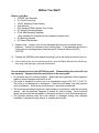
Before You Start!
What’s In the Box
• ATR360 Time Recorder
• (2) Clock Cover Keys
• 18vDC Switching Power Supply
• User Manual
• (25) Sample ATR241 Weekly Time Cards
• (5) Sample Proximity Badges
• Clock Wall Mounting Template
(Also available for download at http://support.acroprint.com)
• (2) Mounting Screws
• (2) Plastic Wall Anchors
1) Unpack clock. Inspect clock for any damages that may have occurred during
shipment. Check box contents for any missing items. If any damages are found or
if any parts are missing please contact Acroprint Customer Service at (800)
334-7190.
2) Connect the ATR360 power adapter and plug it into a wall outlet to turn the clock on.
3)
If this is the first time you’ve turned the clock on, open the Ribbon Access Door with the key
and, using a ball point pen, press the Reset button.
Do not attempt to service the ATR360 yourself. Disassembling the clock will void
the warranty. Always follow the instructions in the user guide.
• Do not place the clock in direct sunlight. Bright light may significantly affect fingerprint
reads or cause fingerprint verification to fail.
• The clock is designed for indoor use in a temperature range of 32-104º F (0-40º C).
The clock is not waterproof or shockproof. Keep the clock away from heat sources
such as radiators. Avoid dusty environments or exposure to chemicals.
• The clock may be placed upright on a solid surface or mounted to a wall with mounting
screws. Use the enclosed template & screws for wall mounting. Avoid locations
where the device will be susceptible to vibrations and shock, such as a slamming door.
• The terminal warranty does not cover defects or damages arising from improper
installation, improper storage, abuse, or unauthorized service.
1
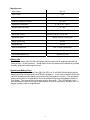
Time Recorder Mode Settings
Mode
Setting
Values
Default
Value
01
Year
2000 – 2099
Year of Mfg
02
Date
1-12 Mo, 1-31 Date
01, 01
03
Time
1-23 Hr, 0-59 Min
12 : 00
04
End of Day Change Time
1-23 Hr, 0-59 Min
00 : 00
05
Set Card Format
(Set “00” for ATR241 cards)
06
Pay Period Type
End Day of Wkly P.Period
Must set 07 for Wkly Card
07
Clock Display Format
08
Adjust Printing Position
Max: 6mm Vert/Horiz adj.
Increase #’s to move up/right
09
00: first row blank
01: prints on 1st row
00
00: Mthly, 01: Wkly
01=Mon…07=Sun
01
07
12 or 24 Hr
12
00-15: Vertical Axis
00-30: Horiz. Axis
08,08
vert,horiz
DST Start Month / Date
DST Start Time
1-12 Mo, 1-31 Date
00-23 Hr
00, 01
02
DST End Month / Date
DST End Time
1-12 Mo, 1-31 Date
00-23 Hr
00, 01
02
10
Print Format
(Independent of display format)
11
Time Card Recognition
00: 24 Hr
01: Decimal Hrs
02: 12 Hr (pm)
00: On, 01: Off
Note: Turn “On” for Mthly cards
Note: pressing “All-Reset” on the control panel will reset all
Time Recorder settings to their factory defaults.
2
02
01
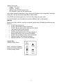
Clock Overview
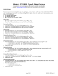
Top View
Front View
• Battery Status Indicator: A fully charged Battery will have (5) bars.
• DST Icon: displays when exiting programming mode
when DST is turned on.
• Each blink of the colon is one sec.
3
Rear View
4
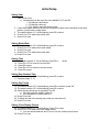
Initial Setup
Setting Year
1. Remove top cover
a. Locate buttons at the top of the clock labeled P4, P5 and P6
i. P4 changes values down
ii. P5 changes values up
iii. P6 is used to save and select modes
2. Locate the program switch to the left of the finger print reader. Move the switch to the down
position, you are now in setup mode
3. The mode indicator “01” will be flashing, press P6 to select
4. Press P4 or P5 to select the current year
5. Press P6 to Save
Setting Month/Date
6. The mode indicator “02” will be flashing, press P6 to select
7. Press P4 or P5 to select the current month
8. Press P6 to save
9. Press P4 or P5 to select the current date
10. Press P6 to save
Setting Time
11.
12.
13.
14.
15.
The mode indicator “3” will be flashing, press P6 to
Press P4 or P5 to select the current hour
Press P6 to save
Press P4 or P5 to select the current minute
Press P6 to save
select
Setting Day Advance Time
16. The mode indicator “04” will be flashing, press P6 to select
17. Complete steps 11-15
Setting Pay Period
18. The mode indicator “05” will be flashing, press P5 to switch to mode “06”
19. The mode indicator “06” will be flashing, press P6 to select
20. Select the pay period type by pressing P4 or P5
a. If the pay period is monthly select 00
b. If the pay period is weekly select 01
21. Press P6 to save
22. To select the end of the weekly pay period you must select 07
23. Press P6 to save
Setting Clock Display Format
24. The mode indicator “07” will be flashing, Press P6 to select
25. Press P4 or P5 to select the clock display format
a. You can choose between the 12 hour or 24 hour (military time) format
26. Press P6 to save
5
Setting Start and End of DST
27. The mode indicator “08” will be flashing, press P5 to switch to mode “09”
28. The mode indicator “09” will be flashing, press P6 to select
29. Press P4 or P5 to select the correct month (US-March)
30. Press P6 to save
31. Press P4 or P5 to select the correct date
32. Press P6 to save
33. Press P4 or P5 to select the correct start time (US-2am)
34. Press P6 to save
35. Complete steps 29-34 to complete the set up for the end of DST
Setting Print Format
36. The mode indicator “10” will be flashing, press P6 to select
37. Press P4 or P5 to select the correct print format
a. 00 – 24 hour (Military Time)
b. 01 – Decimal Hours
c. 02 – 12 hours (pm)
38. Press P6 to save
Setting Time Card Recognition
39. The mode indicator “11” will be Flashing, press P6 to select
40. Press P4 or P5 to select the correct the correct time card format
a. 00 – Monthly, Semi-Monthly
b. 01 – Weekly, Bi-Weekly
41. Press P6 to save
Initial setup is complete. Locate the program switch and move it to the up position. Replace top
cover.
6
Fingerprint Settings Table
A list of the fingerprint settings is shown below:
Setting
Description
Add.U
Add User: Add Fingerprint and/or Proximity badge users to the clock.
Change/delete existing Fingerprint templates or Proximity badge
numbers.
dEL.U
Delete Users: Remove a user or remove Fingerprint templates and/or
Proximity badges from the clock.
rtc.
Real-time Clock: Important! This must be synchronized with the System
Clock (the clock display) or the clock will not function properly.
InO.S
Fingerprint Shift Schedule (In/Out Sch):
“buddy” punching.
dur.
Time Card Allowance Duration: The amount of time an employee has to
insert their time card after scanning their finger or swiping their badges.
The duration can be set from 1 to 60 seconds. The factory default is 3
sec.
All.r
All reset: Resets the Fingerprint Shift Schedule (InO.S) & Time Card
Allowance Duration (Dur.) to factory defaults.
ES
Test Mode: For factory service only. End users should not enter this
mode.
End.P
Exit Fingerprint/Proximity settings.
7
Prevents employees from
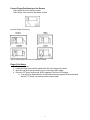
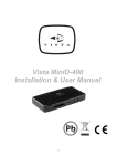
Correct Finger Positioning on the Sensor
Place finger flat on the sensor surface
Place finger in the center of the sensor surface
Incorrect Finger Positioning:
Tips for Improving the Success of Fingerprint Reads
Finger Print Setup
1.
2.
3.
4.
Remove top cover
Locate the finger print switch located to the left of the finger print reader
Move the switch to the up position to turn on the finger print reader.
Press the “FP Setup” button until ADD.U appears in the front LED display
a. If no activity is detected within 30 seconds the setup program will be terminated
and the” FP Setup” up button must be pressed again
8
Add User
5. Press enter
a. Users must be assigned a number user number. You may add up to 150 users and
5 administrators
6. To assign the user a number use the up and down buttons to change each digit. Start with
first digit. (For the number 001 you will start with 0). Press enter to go to the next digit.
a. User numbers will appear Uxxx and can be assigned numbers U001-U150
b. Administrator numbers will appear Axxx and can be assigned numbers A301-A305
7. When you have completed assigning the user, while the last digit is flashing press and
hold the enter button for 3 seconds
8. The LED display will change to F.P.x.x
9. To register a finger print the last digit should be flashing
10. Place the finger on the finger print reader. 3 samples must be giving. If the finger print is
accepted the LED Display will change (F.P.1.1, F.P.1.2, F.P.1.3) after all 3 samples are
giving and accepted the message PASS will appear
11. Now select a second finger for a back up print
a. This is for situations where the primary finger cannot be used because of injuries to
the finger or the reader is unable to read the finger print
12. The LED display will read F.P.2.1
13. Complete step 10 to register the back up print
14. A third back up print may be registered or press cancel
15. Complete steps 5-13 to add another user or press cancel, down, enter to exit
Badge Setup
1.
2.
3.
4.
Remove top cover
Locate the finger print switch located to the left of the finger print reader
Move the switch to the up position to turn on the finger print reader.
Press the “FP Setup” button until ADD.U appears in the front LED display
a. If no activity is detected within 30 seconds the setup program will be terminated
and the “FP Setup” up button must be pressed again
5. Press enter
a. Users must be assigned a number user number. You may add up to 150 users and
5 administrators
6. To assign the user a number use the up and down buttons to change each digit. Start with
first digit. (For the number 001 you will start with 0). Press enter to go to the next digit.
a. User numbers will appear Uxxx and can be assigned numbers U001-U150
b. Administrator numbers will appear Axxx and can be assigned numbers A301-A305
7. To skip finger print recognition press cancel
a. The third digit should be flashing
8. Press the down button the LED display will read “rFId”
9. Press enter the LED display will read “CARD”
10. Scan the card. If the card is successfully scanned the LED display will indicate “PASS”
11. Complete steps 5-10 to add another user badge or press cancel, down, enter to exit
9
Important! Setting the Real-Time Clock (RTC)
A Real-time Clock (RTC) is a computer clock (usually on a chip) that keeps track of the current
time. RTC's are present in almost any electronic device which needs to keep accurate time.
Important! You must always keep the RTC and the System Clock (clock display) synchronized!
Failure to do this will cause the Shift Interval Settings to behave erratically and can even prevent
employees from making normal punches (all punches could result in "err").
Any time you change the system clock you must also synchronize the RTC!
The ATR360 can maintain accuracy to within ±3 sec/wk of the RTC. It is recommended that you
synchronize the RTC with the system time (clock display) at least once a year.
Synchronizing the RTC to the System Clock
1. Open clock lid. Press "FP Setup" button
2. Press "down" until the LED display shows "rtc." Press "Enter"
Two sets of digits will be displayed. The first two digits sets the hour (00-23) & the last two digits
sets the minute (00-59). First set the hour to the current hour. Next set the minute one minute
ahead of the current time so that you can sync the seconds as soon as the minute advances.
3. After setting the minute press "Enter" for 3 seconds. The two digit value for seconds is displayed
(00-59). Set the seconds at "00". Wait for the clock's minute to roll forward, then press and hold
"Enter" for 3 seconds. This will synchronize the RTC to within a few seconds of the Clock Time.
As long as the RTC and Clock Time are set within a minute there shouldn’t be any problems.
Note: if no buttons are pressed for 30 seconds the clock will exit fingerprint settings. If you need
more than 30 seconds for the minute to roll forward you can press "Enter" to toggle between the
seconds digits….this will reset the 20 sec. time-out counter each time you press "Enter".
Fingerprint Shift Intervals (InO.S.)
The ATR360 has (4) default shift intervals:
Shift Intervals prevent employees from punching more than once during a Shift Interval in
order to prevent "buddy punching". If there were no Shift Intervals an employee could use
their fingerprint to punch their time card and then use their fingerprint to punch a buddy's time card.
With the Shift Interval set an employee can punch a buddy's time card, but then if they try to punch
their time card the punch will be rejected and they will have a missing punch. Shift Intervals also
determine which column can be used for punching for a particular Shift Interval (they only restricts
users, administrators can punch anytime).
Note: The ATR360 can have up to 6 Shift Intervals (the number of columns on the time card).
The intervals can be named PE.1 thru PE.12.
10
Editing Shift Intervals
1. Open clock lid. Press "FP Setup" button
2. Press "down" until the LED display shows "InO.S". Press "Enter". "PE.1” will be displayed.
Press "up/down" if you want to edit a different shift.
Press "Enter" to select the shift to edit. Edit the Start of Shift time (hrs : min). Press and hold
"Enter" for 3 sec. to set the Start time ("Pass" will be displayed indicating the start time was
correctly set).
Now edit the Start minute if necessary. Press and hold "Enter" for 3 sec. to set the Start time.
3. Press "Up" or "Down" to select additional shifts for editing.
Deleting a User’s Badge Number
1.
2.
3.
4.
5.
6.
Open clock lid and press "FP Setup".
"Add.U" is displayed.
Press “Down”. "dEL.U" is displayed.
Press “Enter”. Select the User/Admin to delete then press and hold “Enter” for 3 sec.
F.P.1 will flash (if the user has fingerprints enrolled). Press “Up” (skipping all fingerprints)
until “rFId” is displayed. Press “Enter”. If the badge is successfully deleted the LED display
will show “PASS”.
Press “FP Setup” & “Up”. “End.P” is displayed. Press “Enter” to exit FP Setup mode.
Set Ink Color Change Time
1.
2.
3.
4.
5.
6.
7.
8.
9.
10.
11.
12.
13.
14.
Remove top cover
Locate the program switch to the left of the finger print reader. Move the switch to the down
position, you are now in setup mode
Press P1.
a.
P1,P4,P5,P6 will now be flashing
If this is the initial setup you must begin with 01
Press P6 to save
Press P4 or P5 to select the correct hour
Press P6 to save
Press P4 or P5 to select the correct minute
Press P6 to save
Press P4 or P5 to select the correct color
a.
01 – Black
b.
02 – Red
Press P6 to save
Deselect days by pressing P4 or P5 to highlight the day. Press P1 to deselect the day. After
P1 is pressed the day will disappear
a.
7 = Sunday, 1 = Monday….
b.
To reselect the day’s press P4 or P5 until the day is flashing then press P1
Press P6 to save
Complete steps 5-13 to complete the remaining 11 slots or to exit setup move the program
switch to the up position
11
Set Column Change Time Setup
1.
2.
Remove top cover
Locate the program switch to the left of the finger print reader. Move the switch to the down
position, you are now in setup mode
3. Press P3
a.
P3, P4, P5, P6 will now be flashing
4. If this is the initial setup you must begin with 01
5. Press P6 to save
6. Press P4 or P5 to select the correct hour for the first time slot
7. Press P6 to save
8. Press P4 or P5 to select the correct column
a.
Choose a column 1-6
9. Press P6 to save
10. Complete steps 4-9 until all slots are completed or to exit move the program switch to the up
position
12
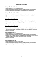
Using the Time Clock
Using the Time Card to Clock In
1.
2.
3.
4.
When clocking in P1, P3 or P5 must be selected
Insert the time card with the current week facing you and the card in the upright position
The time card will automatically feed into the time clock and print the correct time
Remove the time card
Using the Time Card to Clock Out
1.
2.
3.
4.
When clocking out P2, P4 or P6 must be selected
Insert the time card with the current week facing you and the card in the upright position
The time card will automatically feed into the time clock and print the correct time.
Remove the time card
Using a Finger Print to Clock In
1. When clocking in P1, P3 or P5 must be selected
2. Insert the time card with the current week facing you and the card in the upright position
3. Using a registered finger place the finger on the finger print reader. If the finger print is
accepted the time card will automatically feed into the time clock and print the correct time.
4. Remove the time card
Using a Finger Print to Clock Out
1. When clocking out P2, P4 or P6 must be selected
2. Insert the time card with the current week facing you and the card in the upright position
3. Using a registered finger place the finger on the finger print reader. If the finger print is
accepted the time card will automatically feed into the time clock and print the correct time
4. Remove the time card
Using a Badge to Clock In
1. When clocking in P1, P3 or P5 must be selected
2. Insert the time card with the current week facing you and the card in the upright position
3. Scan the badge by placing it in front of the badge scanner, if the badge is accepted the time
card will automatically feed into the time clock and print the correct time
4. Remove the time card
Using a Badge to Clock Out
1. When clocking out P2, P4 or P6 must be selected
2. Insert the time card with the current week facing you and the card in the upright position
3. Scan the badge by placing it in front of the badge scanner, if the badge is accepted the time
card will automatically feed into the time clock and print the correct time
4. Remove the time card
13
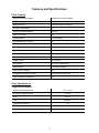
Features and Specifications
Clock Features
User Authentication Method
Fingerprint or Proximity Badge
Display Language
English
Operation Mode
Stand-alone (No PC Interface)
Proximity Card Reader
EM
Operational Battery Backup
Optional
Auto Card Feeder
Yes
Printing Method
9-Pin Dot Matrix
Eliminates Buddy Punching
Yes
Two Color Printing
Yes
Perpetual Calendar
Yes
Auto Fix Positioning
Yes
Power Failure Printing
Yes
Power Failure Memory Retention
Yes
Display Format
12 or 24 hour
Print Format
12 hr, 24 hr, decimal time
External Alarm
Connection Available
Auto Column Changing
Yes
Compatible with Wkly Time Card
Yes (Card Recognition Off)
Card Recognition (front/back)
Yes
Clock Specifications
Fingerprint Recognition
Effective FP Detection Area
16 x 14 mm
Average Recognition Speed
1.2 sec
FRR
≤0.01%
FAR
≤0.0001%
Fingerprint Verification
1:N
Fingerprint Placement Angle
360º
Fingerprint Template Capacity
150
14
Miscellaneous
Input Voltage
DC 18v
Input Current
1.5A
Anti-static Strength
< 15KV
Operational Relative Humidity
10 – 60%
Operational Temperature
0 – 40º C (32 – 104º F)
Storage Relative Humidity
10 – 80%
Storage Temperature
-10 – 60º C (14 – 140º F)
Dimensions (Clock)
197 (w) x 239 (h) x 133 (d) mm
266 (w) x 283 (h) x 208 (d) mm
Dimensions (Box)
Weight (Clock Only)
4.3 Lbs.
Weight (Boxed)
4.5 Lbs.
Time Card Dimension
190 – 192mm x 85-85.5mm
Time Card Weight
300g
Circuit Board Batteries (2)
CR2032 (2 yr life)
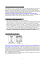
Ribbon Life
The ATR242 ribbon (39-0135-000) will typically last 3 months with 50 employees punching 6
times per day (~18,000 punches). Actual ribbon life will vary based on the number of punches,
humidity, temperature and exposure to air.
Operational Battery Pack
The optional Operational Battery Pack (58-0114-000) is a 12 cell NiMH (Nickel Metal Hydride)
battery pack that recharges when the ATR360 is plugged in. In the event of a power failure the
clock will instantly switch to battery power without any interruption in service. The operational
battery pack allows for full operation of the clock with punching using the fingerprint reader or
Prox badge. The clock will also continue to print on time cards. The LCD backlight is not
activated when the clock is running on battery power in order to save power, however, the LCD
display is plainly visible in a lighted room.
15
Battery Pack Specs:
Voltage: DC 14.4v
Capacity: 1800mA
Standby mode: 30-36hr reserve power
Fully charged: 5 days use (300 punches/day)
Note: Actual battery life depends on many factors such as battery age, temperature, discharge
history, etc., and can vary greatly depending on these factors.
The ATR360 should be plugged in for 12 hours to fully charge the battery pack.
For more information see “Installing the Operational Battery Pack” in the Appendix.
Warning:
Batteries may leak, overheat, catch fire or explode if proper safety & handling procedures are not
followed:
•
DO NOT get batteries wet
•
DO NOT place batteries near heat sources
•
DO NOT use any power supply other than the original
one supplied with the time recorder.
•
DO NOT inverse polarity connection
•
NEVER throw batteries into fire. Properly dispose of
batteries according to local rules and regulations.
•
DO NOT allow anything to short circuit the batteries
•
Dropping a battery may damage the battery.
•
Replace the battery if you suspect any damage.
Internal View
(Internal Control Panel)
Note: turning the Fingerprint
Reader off will also disable the
Proximity Badge Reader.
16
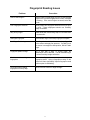
Fingerprint Reading Issues
Problem
Correction
How to select finger?
Use the index or middle finger to enroll; try the left hand
fingers if the right hand fingerprints are worn, damaged
or missing. If the user’s fingers are small, select the
thumb.
Poor Fingerprint Definition
Some people have fingerprint definition that is too poor
to verify. These employees should use Proximity
badge verification.
Dirty or Dry Finger
Wash hands with moisturizing soap or use hand lotion
to hydrate skin.
Damaged Fingerprint
Use alternate finger with backup fingerprint template.
Bad Finger Positioning
Place finger in the middle of the sensor; keep finger flat
on the sensor and apply firm pressure; DO NOT touch
the sensor in an angled or tilted position, DO NOT slide
finger.
Fingerprint pattern change
For a user with a worn or injured finger, the
identification can be affected. Use an alternate finger
or select Proximity badge verification.
Clock has trouble reading most
fingerprints
Clean the fingerprint sensor (see cleaning the
fingerprint sensor. Using a fingerprint overlay on the
sensor will often significantly improve fingerprint reads
(call Acroprint for availability).
Clock has trouble reading
fingerprints on sunny days
Move clock out of direct or bright sunlight.
17
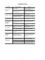
Troubleshooting
Symptom
Possible Problem
Solution
Power Outage
Clock does not
power on
Check circuit breaker. Wait for
power to be restored
The power source was not
properly connected
Check the connections of the
power supply and/or backup
battery
The time was not set correctly
Set correct time
Prolonged power outage
Set time after power is restored
The date was not set correctly
Set correct date
Wrong side of card is inserted
(monthly card)
Flip card over and re-insert
Incompatible time card
Use card approved for the
ATR360
Ribbon cassette not properly
seated
Remove and re-insert ribbon
cassette correctly
The print ribbon is dried out
Replace ribbon cassette
Clock will not print
RTC not synchronized with
display time.
Set RTC
Punches print
in wrong
column
Wrong column selected
(manually selected) or column
change time set incorrectly
Select the correct column (P1 –
P6) or set the correct column
change time
The End of Day set incorrectly
Set End of Day correctly
Time Card Format set incorrectly
Set Time Card Format again
Pay period type is set incorrectly.
Set Pay Period type correctly
The time is incorrect
The date is incorrect
Clock beeps
and rejects
time card
Print too light
Punches print
on wrong row
18
Symptom
Possible Problem
Solution
The clock keeps
losing time
The coin cell battery on the
motherboard needs to be replaced
Replace the coin cell on the
motherboard
Display Off, Clock has
Power
Defective Motherboard
Contact Local Dealer or Acroprint
for repair.
Defective LCD Display
Display is in AM/PM
hours but clock prints
in 24 Hr format
The clock display format and print
format are independent. You must
make sure each is set correctly.
Set the display format correctly
Clock is printing in
wrong color
Ink Color Change Time set
incorrectly
Set the Ink Color Change Time
correctly
Clock print location is
a little off
Clock printing position needs to be
adjusted
Adjust the clock print position
Ribbon cassette not firmly seated.
Press down firmly on ribbon
cassette until it clicks into place.
Ribbon is stuck.
Turn ribbon advance knob
clockwise. If ribbon will not
advance remove cassette and try
advancing again. If ribbon won’t
advance replace ribbon.
Print resistration is
faint or not visible at
all
19
Set the print format correctly
Frequently Asked Questions
1.
Q: Why can’t the clock verify my fingerprint?
A: Possible Causes: The following conditions could result in a failed read.
a. Finger is dry
b. Fingerprint is damaged
c. Finger was not properly positioned when enrolled
d. Employee hasn’t been enrolled
e. Fingerprint sensor is dirty
f. Fingerprint sensor is defective
Correction: Moisturize finger. Enroll a different fingerprint or re-enroll finger. Clean fingerprint
sensor.
2.
Q: The display does not work or parts of it do not work.
A: Possible Causes:
a) Motherboard is defective
b) The LCD display is defective.
Correction: Contact your local dealer or Acroprint for repair.
3.
Q: How do I change an employee from an Administrator
to a user?
A: Delete the employee and re-enroll them as a user.
4.
Q: I checked all settings on my clock and it still won’t
print on my time card.
A: Make sure the RTC and clock display are synchronized.
5. Q: Why is the light for the fingerprint reader not working?
A: Make sure the fingerprint switch is set to “FP ON”.
If this doesn’t correct the problem contact your local dealer or Acroprint for repair.
6.
Q: Can I turn the fingerprint reader off and just use prox badges?
A: No. Sliding the FP switch to "off" also disables the Prox reader.
7.
Q: If I turn the fingerprint reader off can I still punch my time card?
A: Just insert your card. It will automatically be “punched” since user verification is turned
off.
8. Q: I pressed FP setup but why does nothing happen?
A: Make sure the FP Switch is "On". You cannot access the FP settings if the FP Switch is
turned “Off”.
9. Q: Why do I get an "err" message when registering my prox badge?
A: The badge has already been registered to another User ID or the badge could be defective.
10. Q: Why do I get an "err" message when swiping my prox badge?
A: Check to make sure the badge is registered.
11. Q: Can my clock calculate the pay period total?
A: No. The ATR360 does not offer time total calculation.
12. Q: Why does the clock keep rejecting the time card?
A: Check to see if the correct side of the Time Card is inserted. If Time Card Recognition is
turned on your Monthly Time Card must be inserted with the current date on the front side.
If you are using a Weekly Time Card make sure Time Card Recognition is turned off.
13. Q: Why didn’t the time recorder setting I changed not work?
A: Make sure you press [P6] after you enter your setting.
20
14. Q: Why is my clock printing on the wrong row?
A: - Make sure the date is set correctly.
- Make sure the “End of Day” time is set correctly.
- For Weekly pay periods make sure the "End Day of Pay Period" is set correctly.
- Make sure the Pay Period type is is set correctly.
15. Q: I can’t get my clock to print for any employees. It just keeps giving an “err” message.
A: Make sure the display time is synchronized to the RTC time.
For more info on troubleshooting or general “how to” info go to:
http://support.acroprint.com
Maintenance
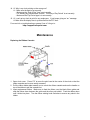
Replacing the Ribbon Cassette
1. Open clock cover. Press “P3” to move the print head to the center of the clock so that the
ribbon cassette can be more easily accessed.
2. Pull the ribbon holder tabs towards you to unlock the ribbon cassette and use the handle on
top of the ribbon to pull the cassette out.
3. Insert replacement ribbon. Make sure to feed the ribbon over the black ribbon guide and
slide the ribbon down between the guide and the silver print shield. Push the ribbon down
until it clicks into place. Turn the ribbon winding knob clockwise to remove any slack in the
ribbon.
21
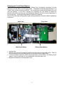
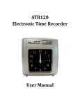
Replacing the Circuit Board Batteries
The ATR360 is equipped with (2) CR2032 3v Lithium Coin Cell batteries: one battery is on the
Main board and the other is on the Display board. The batteries should last approximately 1.5 to
2 years under normal operating conditions. Do not attempt to replace these batteries as it will
void your warranty. If your clock is already out of warranty you can attempt to replace the
batteries yourself but note that you could damage the boards if you short out any components on
the circuit board. Avoid using metal objects to remove the batteries.
Note: All Time Recorder settings will be reset to factory defaults as soon as the Main board battery
is removed.
Back Case
Front Case
Main Board Battery
Display Board Battery
1. Unplug clock.
2. Remove the front cover and the two screws that connect the front and back case. Remove
the front case and lay it flat being careful not to pull any wires or cables loose.
3. To remove batteries press the metal retaining clip away from the battery. The battery should
pop up. It may be necessary to use a small probe to pop the battery out.
4. Replace the batteries and re-assemble clock.
22
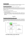
Installing the Operational Battery Pack
First unplug the clock. The door to the battery pack compartment is located on the bottom edge
of the back of the clock. Remove the screw that secures the door. The door may be tightly fitted.
Insert a thin knife blade under the bottom of the door at the screw end and rotate the blade to open
the door.
Insert Blade Here
Connect the battery cable to the connector on the left side of the compartment. Note that the two
ridges on the side of the battery connector should be facing down to line up with the slots in the
clock’s power connector. Turn the battery so that the cable connection is on the bottom. Insert
the battery pack into the clock with the wires inserted into the opening in the side of the
compartment. This is important since the battery door can’t be attached if the battery is sitting on
top of the wires. You may need to use a pencil or screwdriver to push the wires into the opening.
Attach the door by inserting the door tabs into the left side of the compartment and firmly rotating
the door into place. If the door won’t close check to make sure the wires aren’t under the battery.
Plug in the power supply once the battery door is secure. The ATR360 should be plugged in for
12 hours to fully charge the battery pack.
23
Cleaning the ATR360
Do not use cleaning products that contain alcohol or other strong chemicals as they could discolor
or crack the terminal housing. Use a soft damp cloth to remove dirt. Wipe dry.
Cleaning the Fingerprint Sensor
Caution: Do not use any cleaners on the sensor or it could be damaged.
If there is a fingerprint overlay on the fingerprint sensor you can do a quick clean by lightly
pressing a small strip of adhesive tape to the overlay and then slowly peel if off to remove dust &
dirt particles. You can also remove it and clean it with soapy water then rinse and dry and
re-attach to the sensor.
Clean the fingerprint sensor glass as follows:
1. Use a can of compressed air to blow off any loose dust or
dirt particles on the sensor.
2.
Use a soft, lint free non-abrasive dry cloth to wipe the sensor surface. Be careful not to
scratch the surface of the sensor. If there are lint particles on the sensor surface, use clear
adhesive tape to remove particles. Place the clean overlay over the sensor glass (if
applicable).
Appendix
Connecting External Signal Devices (Bells & Horns)
The connections for an external signal device (bells, horns, buzzers, chimes, etc) are made via a
2-wire Green terminal block on the back of the clock above the power jack. Connections are
made by pressing the orange wire release tabs below each wire hole, fully inserting the wire and
releasing the clip. Gently pull on the wires to make sure they are firmly secured in the terminal
block.
24
In order to use a bell or horn a relay is required. Please call Acroprint or your Dealer to order the
relay (PN 01-0230-000).
When a signal is activated by the clock the internal contacts of the relay close and complete the
circuit. These internal contacts are "dry" and supply no voltage. Voltage applied to these
contacts must not exceed 30 volts. The relay then activates the 120v external signal device such
as:
65-0103-000 "Grille Horn"
65-0104-000 "4-1/4" Bell"
65-0105-000 "8" Bell"
For more information about connecting an external signal device using a relay go to
http://support.acroprint.com
Under “Time Clocks & Document Stamps” click on “ATR360 Time Clock” in the drop down menu
and download 06-0346-000 “Connecting an External Signal Device”.
Wall Mounting Instructions
The ATR360 can be placed on a table or desk and it can also be mounted to a wall. A mounting
template is included with the documents for the ATR360. If you misplace the template you can
download it at:
http://support.acroprint.com
Under “Time Clocks & Document Stamps” click on “ATR360 Fingerprint Clock” in the drop down
menu.
Follow the instructions on the template to mount the clock.
Fingerprint Privacy
1. The ATR360 merely captures points of the fingerprint but not
2. The fingerprint points cannot be used to create a fingerprint
image.
3. Acroprint will not be liable for any direct or indirect damages
to use the clock.
4. If you have a question about privacy concerning the use of
employer contact Acroprint.
25
the actual fingerprint image.
resulting from the use or inability
the clock you should have your
Supplies, Parts & Accessories
Part#
Description
01-0230-000
24 Volt Switching Relay Kit
01-0270-000
ATR360 Biometric/Proximity Time Recorder
01-0270-001
ATR240 Time Recorder
06-0400-000
ATR360 User Manual (available on web)
06-0400-001
ATR240 User Manual (available on web)
06-0401-000
Mounting Template (available on web)
09-7000-000
ATR241 Weekly Time Card (pack of 250)
09-7001-000
ATR241 Monthly Time Card (pack of 250)
14-0126-000
Proximity Badges (pack of 15)
39-0135-000
ATR242 Red/Black Ribbon Cassette
45-0182-000
ATR240/360 Case Keys (set of 2)
45-0183-000
125 kHz RFID Key Fob (Pack of 15)
56-0135-000
18v DC Power Supply (w/removable plug)
58-0114-000
ATR240/360 Operational Battery Pack
58-0111-000
CR2032 3v Lithium Coin Cell Battery
64-0103-000
Grille Horn, 120vAC 50/60Hz
64-0104-000
4-1/4" Bell, 120vAC 50/60Hz
64-0105-000
8” Bell, 120vAC 50/60Hz
75-0185-000
US Power Plug (for 56-0135-000)
75-0185-001
Euro Power Plug (for 56-0135-000)
75-0185-002
UK Power Plug (for 56-0135-000)
An updated list of accessories with pricing can be found on the web at: www.acroprint.com
26
Acroprint® Limited Warranty
Should you have any questions concerning your warranty information or supplies, please
contact the dealer or store where you purchased the equipment.
This product is guaranteed to the original purchaser for a period of one (1) year from
original purchase date against defective materials and workmanship when used under
normal operating conditions. The repair or replacement of any defective component or
part and any necessary adjustments will be made free of charge provided that the
machine is shipped prepaid to the factory service center shown below, securely
packaged
and shipped in the original shipping container. This warranty applies to Acroprint products
purchased and retained in the U.S.A. The guarantee is not applicable if the device has
been subject to misuse, abuse, negligence, accidents, power surges and lightning. The
guarantee is not applicable if the serial number has been altered, defaced or removed or
if the device has been tampered with or taken apart by other than authorized service
personnel.
Please return the warranty card on the following page to Acroprint to register your
product. Or, if you would like to register online go to www.acroprint.com. For your
reference, fill out the information below and keep it in a safe place.
Model Number _______________________________________________
Serial Number ________________________________________________
Date Purchased ______________________________________________
Purchased From ______________________________________________
Location ____________________________________________________
Telephone Number ____________________________________________
Acroprint Time Recorder
5640 Departure Drive
Raleigh, NC 27616-1841
27
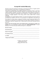
Product Registration Card
Model No._______________________ Serial No._____________________________
First Name______________________ Last Name____________________________
Title_________________________________________________________________
Company Name _______________________________________________________
Address______________________________________________________________
City_______________________
State________ Zip_________________________
Daytime Phone with Area Code____________________________________________
Purchased From___________________
Purchase Date_______________________
Email Address _________________________________________________________
So that we may serve you better, please indicate your primary business activity.
(01) Manufacturing
(04) Government
(02) Wholesale
(05) University / School
(03) Retail
(06) Other _____________________
Number of Employees Using Product
(11) 1 – 10
(14) 50 - 75
(12) 11 - 25
(15) 76 - 100
(13) 26 - 49
(16) 100+
Annual Sales in Dollars
(21) Under $100,000
(22) $100,000 - $250,000
(23) $250,000 - $500,000
(24) $500,000 - $1,000,000
(25) $1 million - $5 million
(26) $5 million and over
Do You Use Microsoft Windows
(31) Yes
(32) No
If not, what operating system do you use? ___________________________________
Comments: ____________________________________________________________
______________________________________________________________________
28
User Notes
06-0400-000 Rev. F