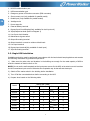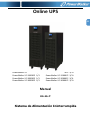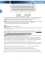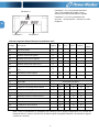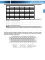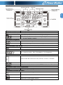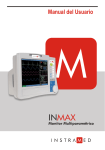
1
Online UPS EN PowerWalker VFI 10000CP PowerWalker VFI 15000CP PowerWalker VFI 20000CP PowerWalker VFI 30000CP 3/3 3/3 3/3 3/3 PowerWalker VFI 10000CP PowerWalker VFI 15000CP PowerWalker VFI 20000CP PowerWalker VFI 30000CP Manual 3/3L 3/3L 3/3L 3/3L EN+ES+IT Uninterruptible Power Supply System EN Please comply with all warnings and operating instructions in this manual strictly. Save this manual properly and read carefully the following instructions before installing the unit. Do not operate this unit before reading through all safety information and operating instructions carefully. Table of Contents 1. SAFETY AND EMC INSTRUCTIONS ................................................................................................. 1 1-1. TRANSPORTATION AND STORAGE ...............................................................................................................1 1-2. PREPARATION.......................................................................................................................................1 1-3. INSTALLATION ......................................................................................................................................1 1-4. OPERATION .........................................................................................................................................2 1-5. STANDARDS .........................................................................................................................................2 2. INSTALLATION AND OPERATION .................................................................................................. 3 2-1. UNPACKING AND INSPECTION ...................................................................................................................3 2-2. REAR PANEL VIEW.................................................................................................................................4 2-3. SINGLE UPS INSTALLATION .....................................................................................................................5 2-4. UPS INSTALLATION FOR PARALLEL SYSTEM ..................................................................................................8 2-5. SOFTWARE INSTALLATION .......................................................................................................................9 3. OPERATIONS ................................................................................................................................ 10 3-1. BUTTON OPERATION ............................................................................................................................ 10 3-2. LED INDICATORS AND LCD PANEL .......................................................................................................... 10 3-3. AUDIBLE ALARM.................................................................................................................................. 12 3-4. SINGLE UPS OPERATION ...................................................................................................................... 12 3-5. PARALLEL OPERATION .......................................................................................................................... 15 3-6. ABBREVIATION MEANING IN LCD DISPLAY ................................................................................................. 16 3-7. LCD SETTING .................................................................................................................................... 17 3-8. OPERATING MODE/STATUS DESCRIPTION ................................................................................................. 23 3-9. FAULT CODE ...................................................................................................................................... 29 3-10.WARNING INDICATOR ......................................................................................................................... 29 3-11.WARNING CODE ................................................................................................................................ 30 4. TROUBLE SHOOTING ................................................................................................................... 30 5. STORAGE AND MAINTENANCE ..................................................................................................... 32 5-1. STORAGE .......................................................................................................................................... 32 5-2. MAINTENANCE.................................................................................................................................... 32 6. SPECIFICATIONS ......................................................................................................................... 33 EN 1. Safety and EMC instructions EN Please read carefully the following user manual and the safety instructions before installing the unit or using the unit! 1-1. Transportation and Storage Please transport the UPS system only in the original package to protect against shock and impact. The UPS must be stored in the room where it is ventilated and dry. 1-2. Preparation Condensation may occur if the UPS system is moved directly from cold to warm environment. The UPS system must be absolutely dry before being installed. Please allow at least two hours for the UPS system to acclimate the environment. Do not install the UPS system near water or in moist environments. Do not install the UPS system where it would be exposed to direct sunlight or nearby heater. Do not block ventilation holes in the UPS housing. 1-3. Installation Do not connect appliances or devices which would overload the UPS (e.g. big motor-type equipment)) to the UPS output sockets or terminal. Place cables in such a way that no one can step on or trip over them. Do not block air vents in the housing of UPS. The UPS must be installed in a location with good ventilation. Ensure enough space on each side for ventilation. UPS has provided earthed terminal, in the final installed system configuration, equipotential earth bonding to the external UPS battery cabinets. The UPS can be installed only by qualified maintenance personnel. An appropriate disconnect device as short-circuit backup protection should be provided in the building wiring installation. An integral single emergency switching device which prevents further supply to the load by the UPS in any mode of operation should be provided in the building wiring installation. Connect the earth before connecting to the building wiring terminal. Installation and Wiring must be performed in accordance with the local electrical laws and regulations. 1 1-4. Operation Do not disconnect the earth conductor cable on the UPS or the building wiring terminals in any time since this would cancel the protective earth of the UPS system and of all connected loads. The UPS system features its own, internal current source (batteries). The UPS output sockets or output terminal blocks may be electrically live even if the UPS system is not connected to the building wiring outlet. In order to fully disconnect the UPS system, first press the “OFF” button and then disconnect the mains. Ensure that no liquid or other foreign objects can enter into the UPS system. The UPS can be operated by any individuals with no previous experience. 1-5. Standards * Safety IEC/EN 62040-1 * EMI Conducted Emission...............................:IEC/EN 62040-2 Category C3 Radiated Emission..................................:IEC/EN 62040-2 Category C3 *EMS ESD.........................................................:IEC/EN 61000-4-2 Level 4 RS........................................................ ...:IEC/EN 61000-4-3 Level 3 EFT......................................................... :IEC/EN 61000-4-4 Level 4 SURGE................................................... :IEC/EN 61000-4-5 Level 4 CS........................................................... :IEC/EN 61000-4-6 Level 3 Power-frequency Magnetic field.............. :IEC/EN 61000-4-8 Level 4 Low Frequency Signals............................:IEC/EN 61000-2-2 Warning: This is a product for commercial and industrial application in the second environment-installation restrictions or additional measures may be needed to prevent disturbances. 2 EN 2. Installation and Operation EN There are two different types of online UPS: standard and long-run models. Please refer to the following model table. Model Type Model Type 10000 10000L 15000 15000L Standard Long-run model model 20000 20000L 30000 30000L We also offer optional parallel function for these two types by request. The UPS with parallel function is called as “Parallel model”. We have described detailed installation and operation of Parallel Model in the following chapter. 2-1. Unpacking and Inspection Unpack the package and check the package contents. The shipping package contains: ● One UPS ● One user manual ● One monitoring software CD ● One RS-232 cable (option) ● One USB cable ● One parallel cable (only available for parallel model) ● One share current cable (only available for parallel model) NOTE: Before installation, please inspect the unit. Be sure that nothing inside the package is damaged during transportation. Do not turn on the unit and notify the carrier and dealer immediately if there is any damage or lacking of some parts. Please keep the original package in a safe place for future use. 3 2-2. Rear Panel View EN Diagram 1: 10000(L)/15000(L) Diagram 2: 30000L Rear Panel Diagram 3: 30000 Rear Panel /20000 (L) Rear Panel Diagram 3: 10000(L)15000(L)/20000(L) Diagram 4: 30000(L) Input/Output Terminal Input/Output Terminal 4 1. RS-232 communication port 2. USB communication port 3. Emergency power off function connector (EPO connector) 4. Share current port (only available for parallel model) 5. Parallel port (only available for parallel model) EN 6. Intelligent slot 7. Power stage fan 8. External battery terminal 9. Bypass Input Circuit Breaker(Only available for dual input unit) 10. Input/Output terminal (Refer to Diagram 2) 11. Line Input circuit breaker 12. Maintenance bypass switch 13. Output Grounding terminal 14. Output terminal: connect to mission-critical loads 15. Line input terminal 16. Bypass input terminal(Only available for dual input) 17. Input Grounding terminal 2-3. Single UPS Installation Installation and wiring must be performed in accordance with the local electric laws/regulations and execute the following instructions by professional personnel. 1) Make sure the mains wire and breakers in the building are enough for the rated capacity of UPS to avoid the hazards of electric shock or fire. NOTE: Do not use the wall receptacle as the input power source for the UPS, as its rated current is less than the UPS’s maximum input current. Otherwise the receptacle may be burned and destroyed. 2) Switch off the mains switch in the building before installation. 3) Turn off all the connected devices before connecting to the UPS. 4) Prepare wires based on the following table: Model Wiring spec (AWG) Input(Ph) Output(Ph) Neutral 10000 10 10 8 10000L 10 10 8 15000 8 8 6 15000L 8 8 6 20000 8 8 6 20000L 8 8 6 30000 8 8 4 30000L 8 8 4 Battery Ground 8 8 8 6 6 6 6 6 6 4 4 5 4 NOTE 1: The cable for 10000/10000L should be able to withstand over 40A current. It is recommended to use AWG 10 or thicker wire for Phase and AWG 8 or thicker wire for Neutral for safety and efficiency. NOTE 2: The cable for 15000/15000L should be able to withstand over 63A current. It is recommended to use AWG 8 or thicker wire for Phase and AWG 6 or thicker wire for Neutral for safety and efficiency. NOTE 3: The cable for 20000/20000L should be able to withstand over 63A current. It is recommended to use AWG 8 or thicker wire for Phase and AWG 6 or thicker wire for Neutral for safety and efficiency. NOTE 4: The cable for 30000/30000L should be able to withstand over 63A current. It is recommended to use AWG 8 or thicker wire for Phase and AWG 4 or thicker wire for Neutral for safety and efficiency. NOTE 5: The selections for color of wires should be followed by the local electrical laws and regulations. 5) Remove the terminal block cover on the rear panel of UPS. Then connect the wires according to the following terminal block diagrams: (Connect the earth wire first when making wire connection. Disconnect the earth wire last when making wire disconnection!) Terminal Block wiring diagram of 10000(L)/15000(L)/20000(L) Terminal Block wiring diagram of 30000(L) 6 EN For dual input unit, if there is two separate input, connect the Line input and bypass input respectively; if the is only one common input, please connect the line input and bypass input together. NOTE 1: Make sure that the wires are connected tightly with the terminals. EN NOTE 2: Please install the output breaker between the output terminal and the load, and the breaker should be qualified with leakage current protective function if necessary. 6) Put the terminal block cover back to the rear panel of the UPS. Warning: (Only for standard model) ● Make sure the UPS is not turned on before installation. The UPS should not be turned on during wiring connection. ● Do not try to modify the standard model to the long-run model. Particularly, do not try to connect the standard internal battery to the external battery. The battery type and voltage may be different. If you connect them together, it maybe causes the hazard of electric shock or fire! Warning: (Only for long-run model) ● Make sure a DC breaker or other protection device between UPS and external battery pack is installed. If not, please install it carefully. Switch off the battery breaker before installation. NOTE: Set the battery pack breaker in “OFF” position and then install the battery pack. ● Pay highly attention to the rated battery voltage marked on the rear panel. If you want to change the numbers of the battery pack, please make sure you modify the setting simultaneously. The connection with wrong battery voltage may cause permanent damage of the UPS. Make sure the voltage of the battery pack is correct. ● Pay highly attention to the polarity marking on external battery terminal block, and make sure the correct battery polarity is connected. Wrong connection may cause permanent damage of the UPS. ● Make sure the protective earth ground wiring is correct. The wire current spec, color, position, connection and conductance reliability should be checked carefully. ● Make sure the utility input & output wiring is correct. The wire current spec, color, position, connection and conductance reliability should be checked carefully. Make sure the L/N site is correct, not reverse and short-circuited. 7 2-4. UPS Installation for Parallel System If the UPS is only available for single operation, you may skip this section to the next. 1) Install and wires the UPSs according to the section 2-3. 2) Connect the output wires of each UPS to an output breaker. 3) Connect all output breakers to a major output breaker. Then this major output breaker will directly connect to the loads. 4) Each UPS is connected to an independent battery pack. NOTE: The parallel system can not use one battery pack. Otherwise, it will cause system permanent failure. 5) Refer to the following wiring diagram: Wiring diagram of parallel system for 10000(L)/15000(L)/20000(L) 8 EN EN Wiring diagram of parallel system for 30000(L) 2-5. Software Installation For optimal computer system protection, install UPS monitoring software to fully configure UPS shutdown. 9 3. Operations 3-1. Button Operation Button EN Function ON/Enter Button Turn on the UPS: Press and hold the button more than 0.5s to turn on the UPS. Enter Key: Press this button to confirm the selection in setting menu. OFF/ESC Button Turn off the UPS: Press and hold the button more than 0.5s to turn off the UPS. Esc key: Press this button to return to last menu in setting menu. Test/Up Button Mute/Down Button Test/Up + Mute/Down Button Battery test: Press and hold the button more than 0.5s to test the battery while in AC mode and CVCF* mode. UP key: Press this button to display next selection in setting menu. Mute the alarm: Press and hold the button more than 0.5s to mute the buzzer. Please refer to section 3-4-9 for details. Down key: Press this button to display previous selection in setting menu. Press and hold the two buttons simultaneous more than 1s to enter/escape the setting menu. * CVCF means Constant Voltage and Constant Frequency. 3-2. LED Indicators and LCD Panel LCD panel LED indicators LED Indicators: There are 4 LEDs on front panel to show the UPS working status: Mode LED UPS On No Output mode Bypass mode AC mode Battery mode CVCF mode Battery Test ECO mode Fault Note: Bypass Line Battery Fault ● ○ ● ○ ○ ○ ● ● ○ ● ○ ○ ● ○ ● ● ● ○ ● ○ ○ ○ ● ○ ● ○ ○ ● ○ ○ ○ ○ ○ ○ ○ ● ● means LED is lighting, and ○ means LED is faded. 10 LCD Panel: EN Display Function Backup time information Indicates the battery discharge time in numbers H: hours, M: minutes, S: seconds Fault information Indicates that the warning and fault occurs. Indicates the fault codes, and the codes are listed in details in section 3-9. Mute operation Indicates that the UPS alarm is disabled. Output & Battery voltage information Indicates the output voltage, frequency or battery voltage. Vac: output voltage, Vdc: battery voltage, Hz: frequency Load information Indicates the load level by 0-25%, 26-50%, 51-75%, and 76-100%. Indicates overload. Indicates the load or the output is short. Mode operation information Indicates the UPS connects to the mains. Indicates the battery is working. Indicates the bypass circuit is working. Indicates the ECO mode is enabled. Indicates the Inverter circuit is working. Indicates the output is working. 11 Battery information Indicates the Battery capacity by 0-25%, 26-50%, 51-75%, and 76-100%. EN Indicates the battery is not connected. Indicates low battery level and low battery voltage. Input & Battery voltage information Indicates the input voltage or frequency or battery voltage. Vac: Input voltage, Vdc: battery voltage, Hz: input frequency 3-3. Audible Alarm Description Buzzer status Muted UPS status Bypass mode Beeping once every 2 minutes Battery mode Beeping once every 4 seconds Fault mode Beeping continuously Yes Warning Overload Beeping twice every second Others Beeping once every second No Fault All Beeping continuously Yes 3-4. Single UPS Operation 1. Turn on the UPS with utility power supply (in AC mode) 1) After power supply is connected correctly, set the breaker of the battery pack at “ON” position (the step only available for long-run model). Then set the line input breaker at “ON” position(for dual input unit, also set the bypass input breaker at “ON”). At this time the fan is running and the UPS enter to power on mode for initialization, several seconds later, UPS operates in Bypass mode and supplies power to the loads via the bypass. NOTE: When UPS is in Bypass mode, the output voltage will directly power from utility after you switch on the input breaker. In Bypass mode, the load is not protected by UPS. To protect your precious devices, you should turn on the UPS. Refer to next step. 2) Press and hold the “ON” button for 0.5s to turn on the UPS and the buzzer will beep once. 3) A few seconds later, the UPS will enter to AC mode. If the utility power is abnormal, the UPS will operate in Battery mode without interruption. NOTE: When the UPS is running out battery, it will shut down automatically at Battery mode. When the utility power is restored, the UPS will auto restart in AC mode. 2. Turn on the UPS without utility power supply (in Battery mode) 1) Make sure that the breaker of the battery pack is at “ON” position (only for long-run model). 2) Press the “ON” button to set up the power supply for the UPS, UPS will enter to power on mode. After initialization UPS will enter to No Output mode, then Press and hold the “ON” button for 0.5s to turn on the UPS, and the buzzer will beep once. 3) A few seconds later, the UPS will be turned on and enter to Battery mode. 12 3. Connect devices to UPS After the UPS is turned on, you can connect devices to the UPS. 1) EN Turn on the UPS first and then switch on the devices one by one, the LCD panel will display total load level. 2) If it is necessary to connect the inductive loads such as a printer, the in-rush current should be calculated carefully to see if it meets the capacity of the UPS, because the power consumption of this kind of loads is too big. 3) If the UPS is overload, the buzzer will beep twice every second. 4) When the UPS is overload, please remove some loads immediately. It is recommended to have the total loads connected to the UPS less than 80% of its nominal power capacity to prevent overload for system safety. 5) If the overload time is over acceptable time listed in spec at AC mode, the UPS will automatically transfer to Bypass mode. After the overload is removed, it will return to AC mode. If the overload time is over acceptable time listed in spec at Battery mode, the UPS will become fault status. At this time, if bypass is enabled, the UPS will power to the load via bypass. If bypass function is disabled or the input power is not within bypass acceptable range, it will cut off output directly. 4. Charge the batteries 1) After the UPS is connected to the utility power, the charger will charge the batteries automatically except in Battery mode or during battery self-test. 2) Suggest to charge batteries at least 10 hours before use. Otherwise, the backup time may be shorter than expected time. 3) Make sure the battery numbers setting on the control board (Please refer to the section 3-4-12 for detailed setting) is consistent to real connection. 5. Battery mode operation 1) When the UPS is in Battery mode, the buzzer will beep according to different battery capacity. If the battery capacity is more than 25%, the buzzer will beep once every 4 seconds; If the battery voltage drops to the alarm level, the buzzer will beep quickly (once every sec) to remind users that the battery is at low level and the UPS will shut down automatically soon. Users could switch off some non-critical loads to disable the shutdown alarm and prolong the backup time. If there is no more load to be switched off at that time, you have to shut down all loads as soon as possible to protect the devices or save data. Otherwise, there is a risk of data loss or load failure. 2) In Battery mode, if buzzer sound annoys, users can press the Mute button to disable the buzzer. 3) The backup time of the long-run model depends on the external battery capacity. 4) The backup time may vary from different environment temperature and load type. 5) When setting backup time for 16.5 hours (default value from LCD panel), after discharging 16.5 hours, UPS will shut down automatically to protect the battery. This battery discharge protection can be enabled or disabled through LCD panel control. (Refer to 3-7 LCD setting section) 6. Test the batteries 1) If you need to check the battery status when the UPS is running in AC mode/CVCF mode, you could press the “Test” button to let the UPS do battery self-test. 2) Users also can set battery self-test through monitoring software. 7. Turn off the UPS with utility power supply in AC mode 1) Turn off the inverter of the UPS by pressing “OFF” button for at least 0.5s, and then the buzzer will beep once. The UPS will turn into Bypass mode. NOTE 1: If the UPS has been set to enable the bypass output, it will bypass voltage from utility power to output terminal even though you have turned off the UPS (inverter). 13 NOTE 2: After turning off the UPS, please be aware that the UPS is working at Bypass mode and there is risk of power loss for connected devices. 2) In Bypass mode, output voltage of the UPS is still present. In order to cut off the output, switch off the line input breaker(for dual input unit, also switch off the bypass line breaker). A few seconds later, there is no display shown on the display panel and UPS is complete off. 8. Turn off the UPS without utility power supply in Battery mode 1) Turn off the UPS by pressing “OFF” button for at least 0.5s, and then the buzzer will beep once. 2) Then UPS will cut off power to output and there is no display shown on the display panel. 9. Mute the buzzer 1) To mute the buzzer, please press the “Mute” button for at least 0.5s. If you press it again after the buzzer is muted, the buzzer will beep again. 2) Some warning alarms can’t be muted unless the error is fixed. Please refer to section 3-3 for the details. 10. Operation in warning status 1) When Fault LED flashes and the buzzer beeps once every second, it means that there are some problems for UPS operation. Users can get the warning indicator from LCD panel. Please check the trouble shooting table in chapter 4 for details. 2) Some warning alarms can’t be muted unless the error is fixed. Please refer to section 3-3 for the details. 11. Operation in Fault mode 1) When Fault LED illuminates and the buzzer beeps continuously, it means that there is a fatal error in the UPS. Users can get the fault code from display panel. Please check the trouble shooting table in chapter 4 for details. 2) Please check the loads, wiring, ventilation, utility, battery and so on after the fault occurs. Don’t try to turn on the UPS again before solving the problems. If the problems can’t be fixed, please contact the distributor or service people immediately. 3) For emergency case, please cut off the connection from utility, external battery, and output immediately to avoid more risk or danger. 12. Operation of changing battery numbers 1) This operation is only available for professional or qualified technicians. 2) Turn off the UPS. If the load couldn’t be cut off, you should remove the cover of maintenance bypass switch on the rear panel and turn the maintenance switch to “BPS” position first. 3) Switch off the line input breaker(for dual input unit, also switch off the bypass input breaker), and switch off the battery breaker (only available for long-run model). 4) Remove the cabinet cover, and disconnect battery wire for standard model. Then modify the jumper of JS3 on the control board to set the battery numbers as following table. JS3 Battery Number in series pin1 & pin2 pin3 & pin4 Pin5 & pin6 pin7 & pin8 18 1 0 0 X 19 0 1 0 X 20 0 0 1 X Note:1 = connect with jumper; 0 = no jumper; x = the pins are for other functions. 5) Modify the battery pack for the setting number carefully. After complete it, put the cover back, switch on the battery breaker for long-run model. 14 EN 6) Switch on the line input breaker(for dual input unit, also switch on the bypass input breaker) and the UPS will enter Bypass mode. If the UPS is in maintenance Bypass mode, turn the maintenance switch to “UPS” position and then turn on the UPS. 3-5. Parallel Operation 1. Parallel system initial startup EN First of all, please make sure all of the UPSs are parallel models and have the same configuration. 1) Turn on each UPS to AC mode respectively (Refer to section 3-4(1)). Then, measure the inverter output voltage of each phase for each UPS to check if the inverter voltage difference between actual output and setting value is less than 1.5V (typical 1V) with multimeter. If the difference is more than 1.5V, please calibrate the voltage by configuring inverter voltage adjustment (Refer to Program 15, 16 and 17, section 3-7) in LCD setting. If voltage difference remains more than 1.5V after calibration, please contact your local distributor or service center for help. 2) Calibrate the output voltage measurement by configuring output voltage calibration (Refer to Program 18, 19, and 20, section 3-7) in LCD setting to make sure the difference between real output voltage and detected value of UPS is less than 1V. 3) Turn off each UPS (Refer to section 3-4(7.)). Then, follow the wiring procedure in section 2-4. 4) Remove the cover of parallel share current cable port on the UPS, connect each UPS one by one with the parallel cable and share current cable, and then screw the cover back. 5) Turn on the parallel system in AC mode: a) Turn on the line input breaker of each UPS(for dual input, also turn on bypass input breaker). After all UPSs enter to bypass mode, measure the output voltage between two UPS for the same phase to make sure the phase sequence is correct . If these two voltage differences are near to zero, that means all connections are correct. Otherwise, please check if the wirings are connected correctly. b) Turn on the output breaker of each UPS. c) Turn on each UPS in turns. After a while, the UPSs will enter to AC mode synchronously and then, the parallel system is completed. 6) Turn on the parallel system in Battery mode: a) Turn on the battery breaker (only available in long-run model) and output breaker of each UPS. NOTE: It’s not allowed to share one battery pack for long-run UPSs in parallel system. Each UPS should be connected to its battery pack. b) Turn on any UPS. A few seconds later, the UPS will enter to battery mode. c) Then, turn on another UPS. A few seconds later, the UPS will enter to battery mode and add to the parallel system. d) If you have the third UPS, follow the same procedure of c). Then, the parallel system is complete. If more detailed information is needed, please contact supplier or service center for parallel operation instruction. 2. Add one new unit into the parallel system 1) You can not add one new unit into the parallel system when whole system is running. You must cut off the load and shutdown the system. 2) Make sure all of the UPS are the parallel models, and follow the wiring refer to section 2-4. 3) Install the new parallel system refers to the previous section. 3. Remove one unit from the parallel system There are two methods to remove one unit from the parallel system: First method: 15 1) Press the “OFF” key twice and each time should be lasted for more than 0.5s. Then, the UPS will enter into bypass mode or no output mode without output. 2) Turn off the output breaker of this unit, and then turn off the input breaker of this unit. 3) After it shuts down, you can turn off the battery breaker (for long-run model) and remove the parallel and share current cables. And then remove the unit from the parallel system. Second method: 1) If the bypass is abnormal, you can not remove the UPS without interruption. You must cut off the load and shut down the system first. 2) Make sure the bypass setting is enabled in each UPS and then turn off the running system. All UPSs will transfer to Bypass mode. Remove all the maintenance bypass covers and set the maintenance switches from “UPS” to “BPS”. Turn off all the input breakers and battery breakers in parallel system. 3) Turn off the output breaker and remove the parallel cable and share current cable of the UPS which you want to remove. Then, remove it from parallel system. 4) Turn on the input breaker of the remaining UPS and the system will transfer to Bypass mode. Set the maintenance switches from “BPS” to “UPS and put the maintenance bypass covers back. 5) Turn on the remaining UPS according to the previous section. Warning: (Only for the parallel system) ● Before turning on the parallel system to activate inverter, make sure that all unit’s maintenance switch at the same position. ● When parallel system is turned on to work through inverter, please do not operate the maintenance switch of any unit. 3-6. Abbreviation Meaning in LCD Display Abbreviation Display content Meaning ENA Enable DIS Disable ATO Auto BAT Battery NCF Normal mode (not CVCF mode) CF CVCF mode SUB Subtract ADD Add ON On OFF Off FBD Not allowed OPN Allow RES Reserved N.L Neutral line loss CHE Check 16 EN EN OP.V Output voltage PAR Parallel, 001 means the first UPS AN The first phase BN The second phase CN The third phase AB The first line BC The second line CA The third line 3-7. LCD Setting There are three parameters to set up the UPS. Refer to following diagram. Parameter 1: It’s for program alternatives. Refer to below tables for the programs to set up. Parameter 1 Parameter 2 and parameter 3 are the setting options or values for each program. Note: Please select “Up” or “Down” button to change the programs or parameters. Parameter 2 Parameter 3 Programs available list for parameter 1: Bypass / AC ECO CVCF Battery Battery No Output mode mode mode mode mode Test Y Y Y Y Y Y Code Description 01 Output voltage Y* 02 Output frequency Y 03 Voltage range for bypass Y 04 Frequency range for bypass Y 05 ECO mode enable/disable Y 06 Voltage range for ECO mode Y 07 Frequency range for ECO mode Y 08 Bypass mode setting Y Y Y Y 09 Maximum battery discharge time setting 10 Reserved Reserved for future options 11 Reserved Reserved for future options 12 Neutral loss detection Y 17 Y Y Y 13 Battery voltage calibration Y Y Y Y Y Y 14 Charger voltage adjustment Y Y Y Y Y Y 15 Inverter A voltage adjustment Y Y Y 16 Inverter B voltage adjustment Y Y Y 17 Inverter C voltage adjustment Y Y Y 18 Output A voltage calibration Y Y Y 19 Output B voltage calibration Y Y Y 20 Output C voltage calibration Y Y Y *Y means that this program can be set in this mode. Note: All parameter settings will be saved only when UPS shuts down normally with internal or external battery connection. (Normal UPS shutdown means turning off input breaker in bypass/no output mode). 01: Output voltage Interface 02: Output frequency Interface 60 Hz, CVCF mode 50 Hz, Normal mode ATO Setting Parameter 3: Output voltage You may choose the following output voltage in parameter 3: 208: Presents output voltage is 208Vac 220: Presents output voltage is 220Vac 230: Presents output voltage is 230Vac 240: Presents output voltage is 240Vac Setting Parameter 2: Output Frequency Setting the output frequency. You may choose following three options in parameter 2: 50.0Hz: The output frequency is setting for 50.0Hz. 60.0Hz: The output frequency is setting for 60.0Hz. ATO: If selected, output frequency will be decided according to the latest normal utility frequency. If it is from 46Hz to 54Hz, the output frequency will be 50.0Hz. If it is from 56Hz to 64Hz, the output frequency will be 60.0Hz. ATO is default setting. Parameter 3: Frequency mode Setting output frequency at CVCF mode or not CVCF mode. You may choose following two options in parameter 3: CF: Setting UPS to CVCF mode. If selected, the output frequency will be fixed at 50Hz or 60Hz according to setting in parameter 2. The input frequency could be from 46Hz to 64Hz. NCF: Setting UPS to normal mode (not CVCF mode). If selected, the output frequency will synchronize with the input frequency within 46~54 Hz at 50Hz or within 56~64 Hz at 60Hz according to setting in parameter 2. If 50 Hz selected in parameter 2, UPS will transfer to battery mode when input frequency is not within 46~54 Hz. If 60Hz selected in parameter 2, UPS will transfer to battery mode when input frequency is not within 56~64 Hz. *If Parameter 2 is ATO, the Parameter 3 will show the current frequency. Note: For single unit, it will have bypass output for a couple of seconds after the unit is powered on. Therefore, to avoid damage on connected devices, it’s strongly suggested to add an additional Output relay board for CVCF application. 18 EN 03: Voltage range for bypass Interface Setting Parameter 2: Set the acceptable low voltage for bypass. Setting range is from 110V to 209V and the default value is 110V. Parameter 3: Set the acceptable high voltage for bypass. Setting range is from 231V to 276V and the default value is 264V. EN 04: Frequency range for bypass Interface Setting Parameter 2: Set the acceptable low frequency for bypass. 50 Hz system: Setting range is from 46.0Hz to 49.0Hz. 60 Hz system: Setting range is from 56.0Hz to 59.0Hz. The default value is 46.0Hz/56.0Hz. Parameter 3: Set the acceptable high frequency for bypass. 50 Hz: Setting range is from 51.0Hz to 54.0 Hz. 60 Hz: Setting range is from 61.0Hz to 64.0Hz. The default value is 54.0Hz/64.0Hz. 05: ECO mode enable/disable Interface Setting Parameter 3: Enable or disable ECO function. You may choose following two options: DIS: disable ECO function ENA: enable ECO function If ECO function is disabled, voltage range and frequency range for ECO mode still can be set, but it is meaningless unless the ECO function is enabled. 06: Voltage range for ECO mode Interface Setting Parameter 2: Low voltage point in ECO mode. The setting range is from -5% to -10% of the nominal voltage. Parameter 3: High voltage point in ECO mode. The setting range is from +5% to +10% of the nominal voltage. 07: Frequency range for ECO mode Interface Setting Parameter 2: Set low voltage point for ECO mode. 50 Hz system: Setting range is from 46.0Hz to 48.0Hz. 60 Hz system: Setting range is from 56.0Hz to 58.0Hz. The default value is 48.0Hz/58.0Hz. Parameter 3: Set high voltage point for ECO mode. 50 Hz: Setting range is from 52.0Hz to 54.0 Hz. 60 Hz: Setting range is from 62.0Hz to 64.0Hz. The default value is 52.0Hz/62.0Hz. 08: Bypass mode setting Interface Setting 19 Parameter 2: OPN: Bypass allowed. When selected, UPS will run at Bypass mode depending on bypass enabled/disabled setting. FBD: Bypass not allowed. When selected, it’s not allowed for running in Bypass mode under any situations. Parameter 3: ENA: Bypass enabled. When selected, Bypass mode is activated. DIS: Bypass disabled. When selected, automatic bypass is acceptable, but manual bypass is not allowed. Manual bypass means users manually operate UPS for Bypass mode. For example, pressing OFF button in AC mode to turn into Bypass mode. 09: Maximum battery discharge time setting Interface 10: Reserved Interface Setting Reserve for future options. 11: Reserved Interface Setting Parameter 3: 000~999: Set the maximum discharge time from 0 min to 999 min. UPS will shut down to protect battery if the discharge time arrives before the battery is under voltage. The default value is 990 min. DIS: Disable battery discharge protection and backup time will depend on battery capacity. Setting Reserve for future options. 12: Neutral loss detection Interface Setting Parameter 2: N.L: Indicates neutral loss detection function. Parameter 3: DIS: Disable the neutral loss detection function. The UPS will not detect the neutral loss or not. ATO: The UPS will automatically detect the neutral is lost or not. If neutral loss is detected, an alarm will be generated. If the UPS is turned on, it will transfer to battery mode. When neutral is restored and detected, the alarm will be muted automatically and the UPS will go back to normal mode automatically. 20 EN CHE: The UPS will automatically detect the neutral loss. If neutral loss is detected, an alarm will be generated. If the UPS is turned on, it will transfer to battery mode. When neutral is restored, the alarm will NOT be muted automatically and the UPS will NOT go back to normal mode automatically. Here, you must mute the alarm and make the UPS go back to normal mode manually. The operation is: Firstly, enter this menu and press the “Enter” key to make the “CHE” flash. Secondly, press the “Enter” key again to activate the neutral detection (check). If neutral is detected, the alarm will be muted and the UPS will go back to normal mode. If neutral is not detected, the UPS will continue alarming and stay on the latest status until the neutral is detected well at next manual checking operation. CHE is default setting. EN 13: Battery voltage calibration Interface 14: Charger voltage adjustment Interface Setting Parameter 2: you may choose Add or Sub to adjust charger voltage Parameter 3: the voltage range is from 0V to 9.9V and the default value is 0V. NOTE: *Before making voltage adjustment, be sure to disconnect all batteries first to get the accurate charger voltage. * Any modification should be suitable to battery specifications. 15: Inverter A voltage adjustment Interface Setting Parameter 2: Select “Add” or “Sub” function to adjust battery voltage to real figure. Parameter 3: the voltage range is from 0V to 9.9V and the default value is 0V. Setting Parameter 2: you may choose Add or Sub to adjust inverter A voltage. Parameter 3: the voltage range is from 0V to 9.9V and the default value is 0V. 16: Inverter B voltage adjustment Interface Setting Parameter 2: you may choose Add or Sub to adjust inverter B voltage*. Parameter 3: the voltage range is from 0V to 9.9V and the default value is 0V. *It will display number 1 under inverter B voltage. 21 or to represent 17: Inverter C voltage adjustment Interface Setting Parameter 2: you may choose Add or Sub to adjust inverter C voltage*. Parameter 3: the voltage range is from 0V to 9.9V, the default value is 0V. *It will display number 2 under inverter C voltage. Setting Parameter 2: it always shows OP.V as output voltage. Parameter 3: it shows the internal measurement value of the output A voltage, and you can calibrate it by pressing Up or Down according to the measurement from an external voltage meter. The calibration result will be effective by pressing Enter. The calibration range is limited within +/-9V. This function is normally used for parallel operation. 19: Output B voltage calibration Interface Setting Parameter 2: it always shows OP.V as output voltage*. Parameter 3: it shows the internal measurement value of the output B voltage, and you can calibrate it by pressing Up or Down according to the measurement from an external voltage meter. The calibration result will be effective by pressing Enter. The calibration range is limited within +/-9V. This function is normally used for parallel operation. *It will display number 1 under voltage. to represent 18: Output A voltage calibration Interface or to represent the output B 20: Output C voltage calibration Interface Setting Parameter 2: it always shows OP.V as output voltage. Parameter 3: it shows the internal measurement value of the output C voltage, and you can calibrate it by pressing Up or Down according to the measurement from an external voltage meter. The calibration result will be effective by pressing Enter. The calibration range is limited within +/-9V. This function is normally used for parallel operation. *It will display number 2 under voltage. 22 to represent the output C EN 3-8. Operating Mode/Status Description EN Following table shows LCD display for operating modes and status. (1) If the UPS is in normal operation, it will show seven screens one by one, which represents 3 phase input voltages (An, bn, Cn), 3 line input voltages (Ab, bC, CA) and frequency in turns. (2) If parallel UPS systems are successfully set up, it will show one more screen with “PAR” in parameter 2 and assigned number in parameter 3 as below parallel screen diagram. The master UPS will be default assigned as “001” and slave UPSs will be assigned as either “002” or “003”. The assigned numbers may be changed dynamically in the operation; Parallel screen Operating mode/status UPS Power On Description When UPS is powered on, it will enter into this mode for a few seconds as initializing the CPU and system. LCD display No-output description When bypass voltage/frequency is out of acceptable range or bypass is disabled (or forbidden), UPS will enter into no-output mode if powering on mode or turning off the UPS. It means the UPS has no output. Alarm beeps every two minutes. LCD display 23 EN AC mode Description When the input voltage is within acceptable range, UPS will provide pure and stable AC power to output. The UPS will also charge the battery at AC mode. LCD display ECO mode Description When the input voltage is within voltage regulation range and ECO mode is enabled, UPS will bypass voltage to output for energy saving. LCD display 24 EN CVCF mode Description When the output frequency is set to “CF”, the inverter will output constant frequency (50 Hz or 60 Hz). At this mode, the UPS will have no bypass output but still charge battery. LCD display 25 Battery mode Description When the input voltage/frequency is beyond the acceptable range or power failure, UPS will backup power from battery and alarm will beep every 4 seconds. LCD display EN Bypass mode Description When input voltage is within acceptable range and bypass is enabled, turn off the UPS and it will enter Bypass mode. Alarm beeps every two minutes. LCD display 26 EN Battery Test Description When UPS is in AC mode or CVCF mode, press “Test” key for more than 0.5s. Then, the UPS will beep once and start “Battery Test”. The line between I/P and inverter icons will blink to remind users. This operation is used to check the battery status. LCD display Warning Description status If some errors occur in the UPS (but it is still running normally), it will show one more screen to represent the warning situation. In the warning screen, the icon will be flashing, and it can show up to 3 error codes and each code indicates one error. You can find the code meaning in the warning code table. LCD display 27 Fault status Description When UPS has fault happened, the inverter will be blocked. It will display fault code in screen, and the icon will light up. You can find the code meaning in the fault code table. LCD display EN 28 3-9. Fault Code Fault code 01 EN Fault event Bus start failure Icon None Fault code 1A 02 Bus over None 1B 03 Bus under None 1C 04 06 11 Bus unbalance Converter over current Inverter soft start failure None None None 21 24 29 12 High inverter voltage None 31 13 Low inverter voltage None 36 14 Inverter A output(line to neutral) short circuited Inverter B output(line to neutral) short circuited Inverter C output(line to neutral) short circuited Inverter A-B output (line to line) short circuited Inverter B-C output (line to line) short circuited Inverter C-A output (line to line) short circuited 15 16 17 18 19 Icon None 41 Fault event Inverter A negative power fault Inverter B negative power fault Inverter C negative power fault Battery SCR short circuited Inverter relay short circuited Battery fuse broken in Battery mode Parallel communication failure Parallel output current unbalance Over temperature 42 DSP communication failure None 43 Overload 46 Incorrect UPS setting None 47 MCU communication failure None 48 Two DSP firmware versions are incompatible. Input and output phases are incompatible None 49 3-10.Warning Indicator Warning Icon (flashing) Alarm Battery low Beeping every second Overload Beeping twice every second Battery unconnected Beeping every second Over charge Beeping every second EPO enable Beeping every second Fan failure/Over temperature Beeping every second Charger failure Beeping every second I/P fuse broken Beeping every second Overload 3 times in 30min Beeping every second 29 None None None None None None None None None 3-11.Warning Code Warning code Warning event Warning code Warning event 01 Battery unconnected 10 L1 IP fuse broken* 02 IP Neutral loss 11 L2 IP fuse broken* 04 IP phase abnormal 12 05 Bypass phase abnormal 21 07 Over charge 22 08 Low battery 33 09 Overload 34 L3 IP fuse broken* Line situations are different in parallel system Bypass situations are different in parallel system Locked in bypass after overload 3 times in 30 minutes Converter current unbalance 0A Fan failure 35 Battery fuse broken 0B EPO enable 3A Cover of maintain switch is open 0D Over temperature 3C Utility extremely unbalanced 0E Charger failure 3D Bypass unstable * These alarms are only for the single input unit. 4. Trouble Shooting If the UPS system does not operate correctly, please solve the problem by Symptom Possible cause No indication and alarm in the front The AC input power is not display panel even though the mains is connected well. normal. EPO function is activated. At The icon and the warning code this time, the EPO switch is in flash on LCD display and alarm “OFF” status or the jumper is beeps every second. open. The icon and flash on LCD display and alarm beeps every second. The external battery is connected. or internal incorrectly UPS is overload. The icon and flash on LCD display and alarm beeps twice every second. Fault code is shown as 43. The icon lights on LCD display and alarm beeps continuously. Fault code is shown as 14, the icon lights on LCD display, and alarm beeps continuously. UPS is overloaded. Devices connected to the UPS are fed directly by the electrical network via the Bypass. After repetitive overloads, the UPS is locked in the Bypass mode. Connected devices are fed directly by the mains. using the table below. Remedy Check if input cable firmly connected to the mains. Set the circuit in closed position to disable the EPO function. Check if all batteries connected well. are Remove excess loads from UPS output. Remove excess loads from UPS output. Remove excess loads from UPS output first. Then shut down the UPS and restart it. UPS is overload too long and becomes fault. Then UPS shut down automatically. Remove excess loads from UPS output and restart it. The UPS shut down automatically because short circuit occurs on the UPS output. Check output wiring and if connected devices are in short circuit status. 30 EN Other fault codes are shown on LCD display and alarm beeps continuously. EN Battery backup time is shorter than nominal value A UPS internal occurred. fault has Batteries are not fully charged Batteries defect The icon and flash on LCD display and alarm beeps every second. Symptom The warning code 02 is shown, the icon flashes on LCD display, and alarm beeps every second. Fan is locked or not working; or the UPS temperature is too high. Possible cause The input neutral wire disconnected. is The L2 or L3 input fuse is broken. 31 Contact your dealer Charge the batteries for at least 7 hours and then check capacity. If the problem still persists, consult your dealer. Contact your dealer to replace the battery. Check fans and notify dealer. Remedy Check and correct the input neutral connection. If the connection is ok and the alarm is still displaying, please refer to the LCD setting section, to enter the neutral loss check menu, to see if the parameter3 is “CHE”, if it is, please press the “Enter” key firstly to make the “CHE” flash and press the “Enter” key secondly to make the UPS clear the alarm. If the warning still exists, please check input fuses of L2 and L3. Replace the fuse. 5. Storage and Maintenance 5-1. Storage Before storing, charge the UPS at least 7 hours. Store the UPS covered and upright in a cool, dry location. During storage, recharge the battery in accordance with the following table: Storage Temperature Recharge Frequency Charging Duration -25°C - 40°C Every 3 months 1-2 hours 40°C - 45°C Every 2 months 1-2 hours 5-2. Maintenance The UPS system operates with hazardous voltages. Repairs may be carried out only by qualified maintenance personnel. Even after the unit is disconnected from the mains, components inside the UPS system are still connected to the battery packs which are potentially dangerous. Before carrying out any kind of service and/or maintenance, disconnect the batteries and verify that no current is present and no hazardous voltage exists in the terminals of high capability capacitor such as BUS-capacitors. Only persons are adequately familiar with batteries and with the required precautionary measures may replace batteries and supervise operations. Unauthorized persons must be kept well away from the batteries. Verify that no voltage between the battery terminals and the ground is present before maintenance or repair. In this product, the battery circuit is not isolated from the input voltage. Hazardous voltages may occur between the battery terminals and the ground. Batteries may cause electric shock and have a high short-circuit current. Please remove all wristwatches, rings and other metal personal objects before maintenance or repair, and only use tools with insulated grips and handles for maintaining or repairing. When replace the batteries, install the same number and same type of batteries. Do not attempt to dispose of batteries by burning them. This could cause battery explosion. The batteries must be rightly deposed according to local regulation. Do not open or destroy batteries. Escaping electrolyte can cause injury to the skin and eyes. It may be toxic. Please replace the fuse only with the same type and amperage in order to avoid fire hazards. Do not disassemble the UPS system. 32 EN 6. Specifications MODEL CAPACITY* INPUT 10000 10000L 10000VA / 9000W 15000 15000L 15000VA / 13500W Voltage Range 30000 30000L 30000VA / 27000W 110 VAC(Ph-N) ± 3 % at 50% Load 176 VAC(Ph-N) ± 3 % at 100% Load Low Line Loss Voltage + 10V 300 VAC(L-N) ± 3 % at 50% Load 276 VAC(L-N) ± 3 % at 100% Load High Line Loss Voltage - 10V 46Hz ~ 54 Hz @ 50Hz system 56Hz ~ 64 Hz @ 60Hz system Three phase with Neutral ≧ 0.99 at 100% Load Low Line Loss EN 20000 20000L 20000VA / 18000W Low Line Comeback High Line Loss High Line Comeback Frequency Range Phase Power Factor OUTPUT Phase Three Phase with Neutral Output voltage 208/220/230/240VAC(Ph-N) AC Voltage Regulation ± 1% Frequency Range (Synchronized Range) Frequency Range (Batt. Mode) 46Hz ~ 54 Hz @ 50Hz system 56Hz ~ 64 Hz @ 60Hz system 50 Hz ± 0.1 Hz or 60Hz ± 0.1 Hz 100%~110%: 10min 110%~130%: 1min >130% : 1sec 100%~110%: 30sec 110%~130%: 10sec >130% : 1sec 3:1 max ≦ 2 % @ 100% Linear Load; ≦ 5 % @ 100% Non-linear Load AC mode Overload Battery mode Current Crest Ratio Harmonic Distortion Line Battery Transfer Inverter Bypass Time Inverter ECO EFFICIENCY AC mode Battery Mode BATTERY Type Numbers Standard Recharge Time Model Charging Current Charging Voltage Type Numbers Long-run Model Charging Current Charging Voltage PHYSICAL Dimension, D X W X H mm Outline Net Weight (kgs) Dimension, D X W X H mm Packaging Net Weight (kgs) ENVIRONMENT Operation Temperature Operation Humidity Operation Altitude** Acoustic Noise Level MANAGEMENT Smart RS-232 or USB Optional SNMP 0 ms 0 ms (When phase lock fails, <4ms interruption occurs from inverter to bypass) <10 ms > 89% > 86% 12 V / 9 Ah 20(18-20 adjustable) 1.0 A ± 10% (max.) 4.0 A ± 10% (max.) 815X250 X826 109 920X380 X1025 127 592X250 X826 38 700X385 X1071 45 >89% >88% >89% >87% 12 V / 9 Ah 12 V / 9 Ah 2 x 20(18-20 adjustable) 2 x 20(18-20 adjustable) 9 hours recover to 90% capacity 2.0 A ± 10% (max.) 2.0 A ± 10% (max.) 273 VDC ± 1% Depending on applications 18 - 20 4.0 A ± 10% (max.) 4.0 A ± 10% (max.) 273 VDC ± 1% 815X250 X826 164 920X380 X1025 182 592X250 X826 40 700X385 X1071 47 815X250 X826 164 920X380 X1025 182 592X250 X826 40 700X385 X1071 47 >90% >89% 12 V / 9 Ah 3 x 20(18-20 adjustable) 4.0 A ± 10% (max.) 12.0 A ± 10% (max.) 815 X 300 X 1000 233.5 920 X 430 X 1205 250.5 815X250 X 826 64 920X380 X 1025 90 0 ~ 40°C (the battery life will down when > 25°C) <95 % and non-condensing <1000m Less than 60dB @ 1 Meter Less than 65dB @ 1 Meter Supports Windows® 2000/2003/XP/Vista/2008, Windows® 7, Linux, Unix, and MAC Power management from SNMP manager and web browser * Derate capacity to 90% when the output voltage is adjusted to 208VAC. **If the UPS is installed or used in a place where the altitude is above than 1000m, the output power must be derated one percent per 100m. ***Product specifications are subject to change without further notice. 33 Online UPS ES PowerWalker VFI 10000CP PowerWalker VFI 15000CP PowerWalker VFI 20000CP PowerWalker VFI 30000CP 3/3 3/3 3/3 3/3 PowerWalker VFI 10000CP PowerWalker VFI 15000CP PowerWalker VFI 20000CP PowerWalker VFI 30000CP 3/3L 3/3L 3/3L 3/3L Manual EN+ES+IT Sistema de Alimentación Ininterrumpida ES Siga estrictamente todas las advertencias e instrucciones en este manual. Guarde este manual antes de instalar las unidades de SAI para leer todas las instrucciones atentamente. No utilice el SAI antes de leer atentamente toda la información de seguridad y las instrucciones de uso. TABLA DE CONTENIDOS 1. INSTRUCCIONES DE SEGURIDAD Y DE COMPATIBILIDAD ELECTROMAGNÉTICA (EMC) ............. 1 1-1. TRANSPORTE Y ALMACENAMIENTO .............................................................................................................1 1-2. PREPARACIÓN ......................................................................................................................................1 1-3. INSTALACIÓN .......................................................................................................................................1 1-4. INTERVENCIÓN .....................................................................................................................................2 1-5. NORMATIVAS .......................................................................................................................................2 2. INSTALACIÓN Y OPERACIÓN ......................................................................................................... 3 2-1. DESEMBALAJE E INSPECCIÓN ....................................................................................................................3 2-2. VISTA DEL PANEL POSTERIOR....................................................................................................................4 2-3. INSTALACIÓN DEL SINGLO SAI ..................................................................................................................5 2-4. INSTALACIÓN DEL SISTEMA SAI EN PARALELO ...............................................................................................8 2-5. INSTALACIÓN DEL SOFTWARE ...................................................................................................................8 3. OPERACIONES ................................................................................................................................ 9 3-1. PULSANTE DE FUNCIONAMIENTO................................................................................................................9 3-3. ALARMA ACÚSTICA ............................................................................................................................. 11 3-4. OPERACIONES DEL SINGLO SAI ............................................................................................................... 11 3-5. OPERACIÓN DE PARALELO ...................................................................................................................... 14 3-6. SIGNIFICADO DE LAS ABREVIACIONES IN DISPLAY LCD .................................................................................. 16 3-7. IMPOSTACIÓN LCD.............................................................................................................................. 16 3-8. MODO OPERATIVO / DESCRIPCIÓN DE ESTADO. ........................................................................................... 23 3-9. CÓDIGOS ERRORES .............................................................................................................................. 28 3-10. INDICADORES DE ADVERTENCIA............................................................................................................. 29 3-11. CÓDIGO DE ARRANQUE ....................................................................................................................... 29 4. RESOLUCIÓN DE PROBLEMAS ..................................................................................................... 30 5. ALMACENAMIENTO Y MANTENIMIENTO ..................................................................................... 32 5-1. CONSERVACIÓN .................................................................................................................................. 32 5-2. MANUTENCIÓN ................................................................................................................................... 32 6. SPECIFICHE ................................................................................................................................. 33 ES 1. Instrucciones de seguridad y de compatibilidad electromagnética (EMC) ES Por favor, lea el siguiente manual del usuario y las instrucciones de seguridad antes de instalar o utilizar su SAI! 1-1. Transporte y Almacenamiento Por favor, sólo llevan el SAI en su embalaje original para protegerlo de los choques y los impactos. El SAI se debe mantenerse en ambiente seco y ventilado. 1-2. Preparación Si el SAI se ha movido de un lugar frío a caliente se puede producir condensación. Antes de la instalación debe estar completamente seco, deja que se climatice por al menos dos horas en ambiente de instalación. No instale el SAI cerca del agua o en ambientes húmedos. No instale el SAI en la luz directa del sol o cerca de fuentes de calor. No bloquee los orificios de ventilación del SAI. 1-3. Instalación No conecte los aparatos o dispositivos que la sobrecarga del SAi, por ejemplo, motores o equipos de gran capacidad. Enchufes de salida o terminales puede ser que no pueden soportar la carga. La posición de los cables deberá estar situada de forma que nadie puede pisotear su camino. El SAI deberá ser instalado en lugares con suficiente ventilación para permitir tener suficiente espacio en todos los lados de SAI, para garantizar la capacidad de ventilación necesaria por el correcto funcionamiento. El SAI está equipado con conexión a tierra. La configuración del sistema debe estar conectada con masa de tierra equipotencial, incluso con los gabinetes de baterías externos. El SAI puede ser instalado sólo por personal cualificado. Un dispositivo de protección adecuado debe estar instalado en el cableado, por no tener problemas en caso de cortocircuitos. La construcción de la instalación eléctrica debe estar correctamente insertado el dispositivo, lo que impide de enchufar otras cargas, más allá de la potencia del SAI. 1 Cuando se ejecuta el cableado del sistema SAI, en primer lugar, conectar la masa de tierra a los terminales. La instalación y el cableado del sistema SAI deben ser ejecutados de conformidad con las leyes y reglamentos eléctricos. 1-4. Intervención En cualquier momento y por cualquier razón, nunca desconecte el cable de tierra de las masas, en SAI o a los terminales de cableado, porque anula la protección de todo el sistema, incluyendo todas las cargas conectadas al SAI. El SAI tiene sus propias características, con fuente de alimentación interna (por ejemplo, baterías). Tomas de corriente o los terminales de salida del SAI puede ser corriente eléctrica, incluso si el SAI no está conectado a la red. Para desactivar completamente el SAI, debe pulsar el botón "OFF" para desconectar la fuente de alimentación. Garantizar que ningún líquido u otros objetos extraños puedan entrar en SAI. El SAI puede ser administrado por cualquier persona, mismo sin ninguna experiencia previa. 1-5. Normativas * Seguridad IEC/EN 62040-1 * EMI Emisiones conductas............................... :IEC/EN 62040-2 Categoría C3 Emission radiadas ....................................:IEC/EN 62040-2 Categoría C3 *EMS ESD.........................................................:IEC/EN 61000-4-2 Nivel 4 RS........................................................ ...:IEC/EN 61000-4-3 Nivel 3 EFT......................................................... :IEC/EN 61000-4-4 Nivel 4 SURGE................................................... :IEC/EN 61000-4-5 Nivel 4 CS........................................................... :IEC/EN 61000-4-6 Nivel 3 Potencia frecuencia de campo magnético. :IEC/EN 61000-4-8 Nivel 4 Señal de baja frecuencia......................:IEC/EN 61000-2-2 Advertencia: Este es un producto comercial e industrial, puede ser necesarias restricciones suplementarias, por evitar perturbaciones. 2 ES 2. Instalación y Operación Existen dos tipos de SAI on-line: modelo estándar y una larga autonomía. Por favor refiérase a la modelo en la siguiente tabla. ES Model 1000 1500 2000 3000 Type Model 1000L 1500L 2000L 3000L Standard model Type Long-run model Opcional en ambos modelos, puede solicitar la función de forma paralela. La instalación y el modelo de SAI en paralelo, se describe en detalle en el capítulo siguiente. 2-1. Desembalaje e Inspección Abra la caja y comprobar el contenido, que debe ser: ● Un SAI ● Un manual ● Un CD de software para el control ● Un cable RS-232 (opcional) ● Un cable USB ● Un enchufe EPO ● Un cable paralelo (para el modelo paralelo) ● Parte del cable de alimentación (para el modelo paralelo) NOTA: Antes de realizar cada operación, controlar el SAI. Asegúrese de que no se dañado durante el transporte. No encienda el SAI y notificar inmediatamente al transportista y distribuidor si hay daños o faltan piezas. Por favor, mantenga el embalaje original en un lugar seguro para uso futuro. 3 2-2. Vista del panel posterior ES Posterior 1: 1000(L)/1500(L)/2000(L) 13 14 15 Figura posterior 2: 3000L 16 17 Figura 3: 1000(L)/1500(L)/2000(L) Terminal de entrada y salida 4 Figura posterior 2: 3000 ES 13 14 15 17 Figura 4: 3000(L) Terminali de entrada y salida 1. RS-232: puerto de comunicación 2. Puerto de comunicación USB 3. Emergencia: apagar la función del conector la EPO 4. Parte del puerto de corriente (disponible sólo para el modelo paralelo) 5. Puerto paralelo (disponible sólo para el modelo paralelo) 6. Inteligente Slot 7. Ventiladores 8. Conector bateria externa 9. Interruptor de entrada 10. Terminales de entrada y salida (Referencia figura 2) 11. Interruptor de entrada 12. Interruptor de bypass 13. Terminales de masa tierra en salida 14. Terminales de salida por conectar las cargas 15. Terminales de las líneas en entrada 16. Terminales de entrada (disponible solo por unità a doble entrada) 17. Terminal de masa tierra en entrada 2-3. Instalación del singlo SAI La instalación y el cableado debe ser realizado de acuerdo con las leyes locales y reglamentos eléctricos, realizados por personal capacitado, con las siguientes instrucciones. 1) Asegúrese que el cable de alimentación y el interruptor, para la construcción de la instalación, son suficientes para una capacidad nominal del SAI, para evitar el riesgo de choque eléctrico o incendio. NOTA: No utilice el enchufe de la pared, porque su poder no es suficiente para encender el SAI, de lo contrario se destruirá por combustión. 2) Apague la fuente de alimentación antes de realizar la instalación. 3) Apague todas las unidades a ser conectados al SAI, antes de conectar. 4) Los cables que conectan el SAI debe tener las características de la siguiente tabla: 5 Modelo Especifica cable de conexión (AWG) Entrada(Ph) Entrada(Ph) Entrada(Ph) 8 1000 10 10 8 1000L 10 10 8 1500 8 8 6 1500L 8 8 6 2000 8 8 6 2000L 8 8 6 3000 8 8 4 3000L 8 8 4 8 8 6 6 6 6 6 6 4 4 4 NOTA 1: El cable para 10000/10000L debe ser capaz de soportar más de corriente 40A. Se recomienda el uso de hilo de 10 AWG o más grueso de alambre para la fase y el GTE-8 o más grueso alambre para neutro para la seguridad y la eficiencia. NOTA 2: El cable para 15000/15000L debe ser capaz de soportar más de corriente 63A. Se recomienda el uso de AWG 8 o alambre más grueso para las fases AWG 6 o más grueso alambre para neutro para la seguridad y la eficiencia. NOTA 3: El cable para 20000/20000L debe ser capaz de soportar más de corriente 63A. Se recomienda el uso de AWG 8 o alambre más grueso para las fases AWG 6 o más grueso alambre para neutro para la NOTA 4: El cable por 30000/30000L debe ser tener más de la corriente 63A. Se recomienda de usar AWG 8 u hilo más grueso por la fase y AWG 4 u hilo más grueso del neutro por la seguridad y eficiencia. Las selecciones de color de los cables debe ser seguido por las leyes locales y reglamentos eléctricos. 5) Retire la tapa del terminal en el panel posterior del SAI. Conecte los cables de acuerdo a los siguientes esquemas de la terminal: (La primera conexión es el cable de la tierra). En el caso de desconexión, el último cable para desconectar es la masa de tierra. Figura delle connessioni per 10000(L)/15000(L)/20000(L) 6 ES ES Figura de las conexiones por 30000(L) Por dos unidades de entrada, si hay dos entradas separadas, conecte la entrada de línea y entrada de la derivación, si es sólo una entrada común, conecte la entrada de línea y entrada de derivación. NOTA 1: Verifique que los cables estén bien conectados a cada pin del terminal. NOTA 2: Por favor, instale el interruptor de salida, entre el terminal de salida y la carga, y el interruptor debe estar calificado con la función de protección de corriente de fuga, si es necesario. 4 Vuelva a colocar la tapa del terminal en el panel posterior del SAI. Atención: (solo por modelo estándar) ● Asegúrese de que el SAI está apagado antes de la instalación. El SAI no debe estar encendido cuando se conecta el cableado. ● No intente modificar el modelo estándar de la gama larga autonomía. En particular, no se conectan las baterías externas al SAI internas. El tipo de batería y la tensión puede ser diferente. Al unir los dos paquetes de baterías, puede causar un choque eléctrico o peligro de incendio. Advertencia: (solamente por SAI a larga autonomía) ● Instalar con mucha atención, un disyuntor CC o otros dispositivo de protección entre el SAI y batería externa. Desconectar la línea CC antes de conectar el paco de batería. NOTA: el interruptor de la batería debe estar en la posición "OFF" y, a continuación, instalar la batería. ● Dar muchas atención a la tensión de bateria en panel posterior. Si desea modificar el número de bateria, asegurarse de modificar la impostación simultáneamente. La conexión de la batería equivocada puede provocar daños permanentes ala SAI. Asegurarse que la tensión de bateria es correcta. ● Dar mucha atención a la polaridad de marcado en el exterior de terminales de la batería y asegúrese de que la conexión de la polaridad es correcta. La conexión no correcta puede causar daños permanentes al SAI. ● Asegúrese que el cableado de masa tierra de protección es correcta. Revise cuidadosamente las especificaciones del cable: color, posición, relación y contacto con la conductancia. ● Asegúrese de la correcta conexión de los cables de entrada y salida. Debe comprobarse cuidadosamente: las especificaciones del cable, color, posición, relación y conductividad. Asegúrese de que la relación L / N es correcto, si se invierte la polaridad va a crear un corto circuito, causando daños a la SAI. 7 2-4. Instalación del sistema SAI en paralelo Si el SAI debe ser utilizado en singla unidad, no tener cuenta de esta sección para la conexión paralela. 1) Instale el SAI y el cable teniendo en cuenta la sección 2-3. 2) Conecte el cable de salida de cada SAI a un interruptor de salida. 3) Conecte todos los interruptores en un solo interruptor, de potencia nominal de todos los SAI en paralelo. Luego de esta importante salida de interruptor se conecta directamente a las cargas. 4) Cada SAI está conectado a una batería de forma independiente. NOTA: Una sola bateria recargable no se puede utilizar por todos los SAI en paralelo. De lo contrario, es el permanente incumplimiento del sistema. 5) Consulte el siguiente esquema: Figura conexiones del sistema en paralelo por 10000(L)/15000(L)/20000(L) Figura conexiones del sistema paralelo por 30000(L) 2-5. Instalación del software Optimizar el sistema SAI ejecutando la instalación de software de vigilancia en ordenador, que configura el 8 ES sistema del SAI en su totalidad. 3. Operaciones 3-1. Pulsante de funcionamiento ES Pulsante Función ON/Enter Botón Activa el SAI: Pulse el botón más de 0.5s para encender el SAI. Enter Key: Pulse para confirmar la selección en el menú de configuración. OFF/ESC Botón Desactiva el SAI: Presione el botón más de 0.5s para apagar el SAI. Presione este botón para volver al último menú de configuración. Test/Up Botón Mute/Down Botón Test/Up + Mute/Down Botón Prueba de la batería: Presione el botón más de 0.5s para probar la batería, mientras que en modo AC, o CVCF. Al pulsar este botón muestra el siguiente menú de selección de la próxima impostación. Apague la alarma: presione el botón más de 0.5s para apagar el zumbador. Por favor, consulte la sección 3-4-9 para más detalles. Al pulsar este botón muestra la lista de selección de menú anterior. Mantenga los dos botones simultáneamente para más de 1s para entrar / salir del menú de configuración. * CVCF = modo de acción del convertidor. 3-2. LED Indicador y panel LCD LED Indicadores: Hay 4 indicadores LED en el panel frontal para mostrar el estado operativo de SAI: Modo Accesión SAI Modo Bypass Modo AC Modo Bateria Modo CVCF Test Bateria Modo ECO Guasto Accesión SAI LED Bypass Línea Bateria Guasto ● ○ ● ○ ○ ○ ● ● ○ ● ○ ○ ● ○ ● ● ● ○ ● ○ ○ ○ ● ○ ● ○ ○ ● ○ ○ ○ ○ ○ ○ ○ ● Nota: ● LED iluminado, ○ LED parado 9 Pannello LCD: ES Display Funzione Informazioni del tempo di autonomia Indica il tempo di autonomia con orologio analogico. Indica il tempo d’autonomia con orologio digitale. H: ore, M: minuti, S: secondi Informazioni del guasto Indica che l'allarme e di guasto. Indica il codice del guasto, elencati in dettaglio nella sezione 3-9. Funzionamento senza allarmi Indica che l’allarme sonoro è disabilitato. Informazione uscita e batteria Indica la tensione d’uscita, frequenza, o tensione batteria. Vac = tensione uscita – Vdc = Volt batteria – Hz = frequenza Informazioni del carico Indica il livello del carico da: 0-25%, 26-50%, 51-75%, e 76-100%. Indica il sovraccarico. Indica un cortocircuito in: uscita dell’UPS o del carico allacciato. Informazioni delle uscite programmabili Indica se le prese programmate stanno funzionando. Informazioni sul modo operativo Indica se l’UPS è collegato alla rete. Indica che la batteria è attiva. Indica che il circuito bypass è attivo. 10 Indica che il modo ECO è attivo. Indica che il circuito inverter è attivo. Indica le prese d’uscita sono attive. Informazioni batteria ES Indica il livello della batteria, da: 0-25%, 26-50%, 51-75%, e 76-100%. Indica un guasto alla batteria. Indica la bassa tensione della batteria. Informazione tensione d’ingresso e Batteria Indica la tensione d’ingresso, o frequenza, o tensione della batteria. Vac = tensione ingresso, Vdc = Volt batteria, Hz = frequenza d’entrata 3-3. Alarma acústica Descripción Información acústica Muto Estado del SAI Modo de bypass Beep cada segundo 2 minutes batería de modo de Beep cada segundo 4 segundos Si no el modo de Beep continuo Si Advertencia Sobrecarga 2 beep cada segundo Otro Beep cada segundo No Fallos Beep continuo Todo Si 3-4. Operaciones del singlo SAI 1. Ascensión de SAI con línea AC (en modo AC) 1) Después de que el SAI está conectado correctamente, poner el interruptor de la batería interna en la posición "ON" (paso sólo por modelo a larga antonimia.) A continuación, ajuste el interruptor de entrada a "ON". En este momento, el ventilador está funcionando, colocando el interruptor de salida del SAI en la posición ON, ‘‘la capacidad del SAI a las cargas a través del by-pass. El SAI está en modo de operación de bypass. NOTA 1: Cuando el SAI está en modo de bypass, la tensión de salida es de la red eléctrica. En el modo de bypass, la carga no está protegida por el SAI. Para proteger su carga, debes activar el interruptor al interior del aparato. Refiérase a la siguiente etapa. 2) Mantenga pulsado el botón de ACENSIÓN por 0.5S para encender el SAI y el timbre suena. 3) Después de unos segundos, el SAI pasa a CA. Si el SAI es idóneo, está en el modo de batería sin interrupción. NOTA: Si el SAI se para automáticamente en modo bateria se restaura y inicia automáticamente en modo de CA. 2. Arrancar el SAI en modo bateria 11 1) Asegúrese de que el interruptor de la batería esté en posición "ON" (para el modelo con batería de larga autonomía). 2) Presione el botón "ON" por 0.5s para activar el SAI y la alarma suena una vez. 3) Después de algunos segundos, el SAI se encenderá en el modo de batería. 3. Conectar los dispositivos en SAI. Después de la SAI está activada, se puede conectar dispositivos al SAI. 1) Encienda el SAI y en la pantalla LCD controlar el nivel de carga total. 2) Si necesario eliminar rápidamente las cargas inductivas, por ejemplo: impresora laser, o las cargas no idóneas para entrar en la capacidad nominal del SAI. 3) Si el SAI está sobrecargado, el zumbador emite un pitido cada dos segundos. 4) Para un funcionamiento seguro, la carga conectada no debe superar el 80% de la capacidad nominal del SAI. 5) Si la sobrecarga persiste, el SAI se transfieren automáticamente a bypass. Después de la eliminación de la sobrecarga, el SAI sigue no funcionar correctamente, identificar la causa, ya que pueden ser de distinta naturaleza. Cuando el SAI detecta deficiencias de funcionamiento, para iniciar el SAI en un uso normal, proceder como se especifica en la sección 3.4 - 2 Encender el SAI en modo batería. 4. Cargar la bateria 1) Después que el SAI está conectado y suministra energía, el cargador automáticamente carga la bateria, no cuando se ejecuta en modo de batería o en la auto-prueba. 2) Se sugiere de cargar la bateria durante al menos 10 horas antes de su uso. En caso contrario, el tiempo de autonomía puede ser más corto que el tiempo asignado. 3) Asegúrese de ajustar el número de la batería en el panel de control, que debe ser coherente con la exacta concesión. (Refiérase a la Sección 3-4-12, para conocer los detalles de configuración). 5. Funcionamiento en modo bateria 1) Si el SAI está en modo de batería, el zumbador emite un sonido diferente de acuerdo a la capacidad de la batería. Si la capacidad de la batería es más del 25%, la alarma suena una vez cada 4 segundos si el voltaje de la batería se reduce a la alarma, el zumbador emite un pitido rápido (una vez cada segundo), para recordar que la batería está para agotarse y el SAI se apagará automáticamente mucho pronto. La utilidad de las cargas no críticas, pueden pararse rápidamente, inmediatamente, salvar los datos que están en elaboración. Son diferentes las cargas críticas, cuando se conecta y programado correctamente. 2) en modo batería, si el sonido molesta, los usuarios pueden presionar el botón Mute para silenciar el timbre. 3) Por el modelo a autonomía, el tiempo depende de la capacidad de la batería externa. 4) El período de autonomía puede variar en diferente ambiente de temperatura y tipo de carga. 5) Cuando se imposta el tiempo de autonomía por 16,5 horas (valor predeterminado en el panel LCD), el SAI se apagará automáticamente para proteger la batería. Esto tiempo puede ser activado o desactivado a través del panel de control LCD. (Ver sección 3-7 Configuración de pantalla). 6. Prueba de la bateria 12 ES 1) Para comprobar el estado de la batería cuando el SAI está operando en un modo red CA CVCF / ECO modo, pulsar el botón "Test" el SAI puede ejecutar auto-test de batería. 2) Para mantener el sistema fiable, el SAI automáticamente realizar auto-test periódicamente. El período por predefinido es una vez por semana. 3) Los usuarios pueden configurar su auto-test bateria a través del software. ES 4) Si el SAI está en batería auto-test, la pantalla LCD y el zumbador será como si fuera de funcionamiento en modo de batería, excepto que el LED batería parpadea. 7. Apagar el SAI en funcionamiento modo red AC 1) Para apagar el inversor del SAI pulse el botón "OFF", por más de 0.5s, la alarma suena una vez. El SAI se convertirá en modo bypass. NOTA 1: Si el SAI se ha establecido para permitir el funcionamiento que en bypass de la tomas, todos los terminales serán de la misma manera (bypass). NOTA 2: Después apagar el SAI, ser conscientes que el SAI está trabajando para bypass y no hay riesgo de pérdida de energía para los dispositivos conectados. 2) En el modo de bypass, la tensión de salida del SAI está presente. Para desactivar completamente el SAI es necesario interrumpir el interruptor interior del SAI e interruptor de entrada en OFF. Después de unos segundos, la pantalla se apaga completamente. 8. Apagar el SAI en ausencia de red CA, funcionamiento en modo bateria 1) Para apagar el SAI pulse el botón "OFF", por lo menos, 0.5s, la alarma suena una vez. 2) El SAI termina su función, con la pantalla del panel parada. 9. Apagar la señal acústica 1) Po desactivar la alarma, presione el botón de "Mute", por lo menos, 0.5s. Si pulsa de nuevo, el sonido está desactivado, el zumbador emite un pitido. 2) Algunos de los avisos de alarma, no se puede desactivar a menos que el error se ha resuelto. Para obtener más información, consulte la sección 3-3. 10. Operaciones en un estado de alarma 1) Cuando LED Fauld parpadea y el zumbador emite un pitido cada segundo, significa que hay algunos problemas de funcionamiento del SAI. Los usuarios pueden obtener el código de error en la pantalla LCD. Para obtener más información compruebe la tabla de solución de problemas en el Capítulo 4. 2) Algunos de los avisos de advertencias no se puede desactivar a menos que el error se ha resuelto. Para obtener más información, consulte la sección 3-3. 1 11. Operaciones en modo de guatos 1) Cuando LED Fault y zumbador emite un pitido continuo, significa que hay un error fatal en SAI. Los usuarios pueden obtener el código de error en el panel. Para obtener más información, gustos ver la tabla en el Capítulo 4. 3) Verifique las cargas, el cableado, la ventilación, la utilidad, la batería, el fracaso para resolver este. Si los problemas no se resuelven, no intente encender el SAI. Si los problemas no pueden resolverse de inmediato, ponerse en contacto con el servicio asistencia. 4) En el caso de una emergencia inmediatamente interrumpir la conexión de red CA, batería externa y la salida, para evitar un mayor riesgo o peligro. 12. Operaciones para cambiar el número de la batería 1) Esta operación sólo está disponible para los profesionales o técnicos. 13 2) Apague el SAI. Si la carga no se puede ser excluida, debe quitar la tapa de mantenimiento de bypass, en la parte trasera y gire el desviador de SAI a BPS. 3) Apague el interruptor de entrada, y apagar el interruptor de la batería (sólo para el modelo de larga duración de la batería). 4) Retire la tapa de la SAI y desconectar la batería para el modelo estándar. A continuación, cambie el puente JS3 en la placa de control para ajustar el número de la batería como se muestra en la siguiente tabla. JS3 Numero baterías en series pin1 & pin2 pin3 & pin4 Pin5 & pin6 pin7 & pin8 18 1 0 0 X 19 0 1 0 X 20 0 0 1 X Nota: 1 = conectada con el puente, 0 = no hay puente, X = los pin son para otras funciones. 5) Modificar la batería para el establecimiento de los números con cautela. Después de terminar, vuelva a colocar la tapa, gire el interruptor de la batería es el modelo de larga autonomía. 6) Gire el interruptor automático de entrada (para dos unidades de entrada, incluyendo el interruptor de bypass de entrada) e inserte en modo de bypass el SAI. Si el SAI está en modo de bypass "mantenimiento", colocar el interruptor de mantenimiento a SAI y vuelva a encender el SAI. 3-5. Operación de paralelo 1. Sistema de conexión paralela En primer lugar, asegúrese de que todos los modelos de SAI son paralelos y tienen la misma configuración. 1) Encienda todos los SAI en corriente alterna CA, respectivamente (ver sección 4.3 (1)). Luego, mida la tensión de salida del inversor de las fases de cada SAI para verificar que, con un multímetro, la diferencia de tensión entre la producción y el valor de ajuste es inferior a 1,5 V (típica es 1 V). Si la diferencia es superior a 1,5 V, calibrar la tensión de ajuste de la tensión mediante la configuración del inversor (ver los programas 15, 16 y 17 de la sección (3-7) DISPLAY LCD. Si la diferencia de tensión se mantiene más de 1,5 V después de la calibración, por favor póngase en contacto con el centro de servicio para obtener ayuda. 2) Calibrar el voltaje de salida medida configuración de voltaje de salida calibración (hacer referencia a programa 18, 19 y 20, la sección (3-7) en la fijación de la pantalla LCD para asegurarse que la diferencia entre la tensión de salida real y el valor detectado del SAI es inferior a 1V. 3) Apague todos los SAI (consulte la Sección 3.4 (7.)). Por lo tanto, seguir el procedimiento de cableado, la sección 2-4. 4) Retire la tapa de la distribución de cable de puerto paralelo en el SAI, conectar cada uno a un SAI con el cable paralelo y cable de distribución, luego tornilla la tapa de nuevo. 5) Encender el sistema de forma paralela en modo CA: a) Conectar el interruptor de línea de entrada de energía de cada SAI (por la doble entrada, también el interruptor de entrada bypass). Después de que todos los SAI entrarán en el modo de bypass, hacer mensuración de la tensión de salida entre dos SAI para la misma fase para asegurar que la secuencia de fase es correcta. Si estas diferencias de tensión están cerca de cero, esto significa que todas las conexiones son correctas. De lo contrario, compruebe si los cables están conectados correctamente. b) Encienda el interruptor de salida de cada SAI. 14 ES c) Encienda cada SAI uno a tras otro. En poco tiempo los SAI entran en modo CA síncrono y el sistema paralelo se ha completado. 6) Encender el sistema de forma paralela en modo bateria: a) Conectar el interruptor de la batería (sólo para SAI a larga autonomía) y interruptor de salida de cada SAI. ES NOTA: No se le permite compartir una batería de SAI de larga autonomía en paralelo. Cada SAI debe ser conectado a su batería. b) Encienda un SAI, después de unos segundos, entra en modo batería. c) Conectar otro SAI, después de unos segundos y agregar al sistema paralelo. d) Si se agrega un terceros SAI, siga el mismo procedimiento c) y el sistema paralelo se ha completado. Si usted requiere información adicional sobre la educación de los SAI en paralelo, por favor póngase en contacto con el centro de asistencia. 2. Adicionar una nueva unidad al sistema paralelo. 1) No se puede agregar una nueva unidad en paralelo, cuando todo el sistema está funcionando. Tiene que interrumpir la carga y apagar el sistema. 2) Asegúrese de que todos los SAI son de modelos paralelas, y siga el cableado haciendo referencia a 2-4. 3) Instale el nuevo sistema paralelo se refiere a la sección anterior. 3. Eliminar un SAI de sistema en paralelo Hay dos formas de eliminar un sistema de SAI en paralelo. Primero método: 1) Presionar el botón "OFF" dos veces, y cada vez por más de 0,5 s, el SAI entra en modo de bypass o sin salida. 2) Apague el interruptor de salida y de entrada del SAI. 3) Después el apague de la unidad, puede apagar el interruptor de la batería (Por SAI de larga autonomía), retire los cables de paralelo y distribución, a continuación, retire la unidad del sistema paralelo. Segundo método: 1) Si el bypass es anormal, no es posible quitar el SAI sin interrupción. Debe apagar la carga y después el sistema. 2) Asegúrese que la impostación de bypass está activada en cada SAI, a continuación, apague el sistema en funcionamiento. Todas los SAI se transferirán en modo bypass. Quite todas las placas de derivación de mantenimiento y los interruptores de mantenimiento para establecer los "SAI" a "BPS". Apague todos los interruptores de entrada y de batería del sistema paralelo. 3) Apague el interruptor de salida y retire el cable paralelo del cable y de distribución de los SAI que desea remover y retirar el SAI del sistema paralelo. 4) Conectar el interruptor de entrada de SAI restantes, el sistema transfiriere en modo bypass. Impostar los interruptores de "BPS" a "SAI", y tornilla la placa de bypass. 5) Encienda los SAI permanecido, en base a sesión anterior. Nota: (Sólo para el sistema en paralelo) ● Antes de encender el sistema paralelo que activa el inversor, asegúrese de que todas las unidades son en la misma posición de cada SAI. ● Cuando el sistema esté paralelo con el inversor en función, no utilice el interruptor (BPS-SAI) de cada SAI. 15 3-6. Significado de las abreviaciones in display LCD Abreviación Contenido en display Significado ENA Activado DIS Deshabilitado ATO Automático BAT Bateria NCF Modo normal modo (no por modo CVCF) CF Modo CVCF SUB Sacar ADD Adicional ON On OFF Off FBD No consentido OPN Permiso RES Reservado N.L Perdida de la línea neutral CHE Controlo OP.V Voltaje de salida PAR Paralelamente, 001 significa que el primer AN La primera fase BN La segunda fase CN La tercera fase AB La primera línea BC La segunda línea CA La tercera línea 3-7. Impostación LCD Hay tres parámetros para definir el SA 16 ES Parámetro 1: Es por programa alternativo. Tiene 15 programas de instituir. Hacer referencia a la tabla reportada en seguida. Parametro 1 Parámetro 2 y 3 son los parámetros de opciones de impostación o valores por cada programa. ES Parametro 2 Parametro 3 Lista de programas disponibles para el parámetro en 1: Código Descripción 01 Tensione salida Si* 02 Frecuencia salida Si 03 Gamma di tensione bypass Si 04 Gamma di frecuencia bypass Si 05 Modo ECO modo activar o desactivar Si 06 Gamma di tensione modo ECO Si 07 Bypass Impostación gama de frecuencia modo AC ECO CVCF Bateria Si Si Si Test bateria Si ECO 08 Impostación modo Bypass Si Si 09 Impostación tiempo autonomía Bateria Si Si 10 Reservado Reservado por futuro 11 Reservado Reservado por futuro 12 Detección de pérdida de neutro Si Si Si Si Si Si 13 Calibración de voltaje de la batería Si Si Si Si Si Si 14 Tensión bateria Reglamento Si Si Si Si Si Si 15 Un reglamento del inversor de tensión Si Si Si 16 Ajuste de la tensión B del inversor Si Si Si 17 Ajuste de los inversores de potencia C Si Si Si 18 Una calibración de la tensión Si Si Si 19 B calibración de la tensión Si Si Si 20 C tensión de calibración Si Si Si Si * Esto significa que este programa se puede configurar en este modo. Nota: Todos los parámetros se guardarán sólo cuando el SAI se apaga normalmente con conexión de la batería interna o externa. (Normal SAI shutdown significa apagado automático de entrada en bypass / salida sin corriente). 17 01: Voltaje de salida Interface 02:Voltaje entrada Interface 60 Hz, CVCF modo Impostación Parámetro 3: tensión de salida Es posible elegir las siguientes salidas de tensión en parámetro 3: 208 indica tensión de salida = 208Vac 220: indica tensión de salida = 220Vac 230: indica tensión de salida = 230Vac 240: indica tensión de salida = 240Vac Impostación Parámetro 2: frecuencia salida Ajuste de la frecuencia de salida. Puede elegir tres opciones en el parámetro 2: 50.0Hz: La frecuencia de salida es 50.0Hz. 60.0Hz: La frecuencia de salida es 60.0Hz. ATO: Si no está seleccionada, la frecuencia de salida es en base a la última frecuencia apostada. Si es de 46Hz a 54Hz, la frecuencia de salida es 50.0Hz. Si es de 56Hz a 64Hz, la frecuencia de salida es 60.0Hz. ATO es el valor por defecto. 50 Hz, Normal modo Parámetro 3: modo de frecuencia. Impostación de la frecuencia de salida en modo CVCF o no modo CVCF. Se puede elegir dos opciones en el parámetro 3: CF: Impostar SAI por modo CVCF. Si es seleccionada, la frecuencia de salida y fijada a 50 Hz o 60 Hz en base al parámetro de impostación 2. La frecuencia de entrada puede ser de 46Hz hasta 64Hz. NCF: Impostar SAI en modo normal (no modo CVCF). Se es ATO seleccionada, la frecuencia de salida será la sincronización con la frecuencia de entrada entre 46 ~ 54 Hz a 50 Hz o entre 56 ~ 64 Hz a 60 Hz en base al parámetro de impostación 2. Si seleccionado a 50 Hz en parámetro 2, el SAI se transfiere en bateria cuando la frecuencia de entrada no es entre 46 ~ 54 Hz. Si seleccionado 60Hz en parámetro 2, el SAI se transfiere en bateria cuando la frecuencia de entrada no es entre 56 ~ 64 Hz. * Si es Parámetro 2 ATO, el Parámetro 3 visualiza la actual frecuencia. Tenga en cuenta: por una sola unidad, pasará por alto la salida durante unos segundos después de que el equipo está encendido. Por lo tanto, para evitar daños a los dispositivos conectados, se recomienda añadir una tarjeta de relé de salida adicional para la aplicación CVCF. 03: Gama tensión por bypass Interface Impostación Parámetro 2: Impostación aceptable per bypass a baja tensión. Gama de regulación de 110V hasta 209V y el valor predefinido es 110V. Parámetro 3: Impostación aceptable por alta tensión por bypass. Gama de regulación de 231V hasta 276V y el valor de predefinido es 264V. 04: Gama de frecuencia por bypass Interface Impostación Parámetro 2: Impostación a baja frecuencia aceptable por el bypass. 50 Hz sistema: Campo de regulación es de 46.0Hz hasta 49.0Hz. 60 Hz sistema: Campo di regulación es de 56.0Hz hasta 59.0Hz, Valor predefinido es 46.0Hz/56.0Hz. Parámetro 3: Impostación de la frecuencia aceptable por el bypass. 18 ES 50 Hz: Campo de regulación de 54,0 Hz Hasta 51.0Hz. 60 Hz: Campo de regulación es de 61.0Hz hasta 64.0Hz. El valor predefinido es 54.0Hz/64.0Hz. ES 05: Modo ECO activar o desactivar Interface Impostación Parámetro 3: Activar o desactivar la función ECO. Se puede elegir dos siguientes hipótesis: DIS: deshabilitar la función ECO ENA: activar la función ECO ECO Se la función es desactivada, gama de tensión y de frecuencia por modo ECO puede ser mismo fijada, me es sin significado, a menos que la función ECO es habilitada. 06: Gamma tensione per modo ECO Interface Impostación Parámetro 2: baja tensión punto en modo ECO. La gama de regulación es del 5% hasta 10% de la tensión nominal. Parámetro 3: Alta tensión en modo ECO. La gamma di regulación es de 5% hasta 10% de la tensión nominal. 07: Gama de frecuencia por modo ECO Interface Impostación Parámetro 2: Impostación di baja tensione per modo ECO. 50 Hz sistema: Campo de regulación es de 46.0Hz hasta 48.0Hz. 60 Hz sistema: Campo di regulación è da 56.0Hz a 58.0Hz. El valor predefinido es 48.0Hz/58.0Hz. Parámetro 3: Impostación a alta tensión por modo ECO. 50 Hz: Campo di regulación da 54,0 Hz a 52.0Hz. 60 Hz: Campo di regulación è da 62.0Hz a 64.0Hz. El valor predefinido es 52.0Hz/62.0Hz. 08: Impostación modo bypass Interface Impostación Parámetro 2: OPN: Bypass consentido. Cuando viene seleccionado, verá ejecutado del SAI en base el modo bypass activar o desactivar la impostación. FBD: bypass non es permitido. Cuando viene seleccionado, no es consentido por el funcionamiento en modo bypass, será por cualquier situación. Parámetro 3: ENA: Bypass activado. Cuando viene seleccionado, viene activado el modo bypass. DIS: bypass deshabilitado. Cuando seleccionado, es aceptable el bypass automático, me manual el bypass no es consentido. Bypass manual significa que los usuarios manualmente pueden operar en modo Bypass. Ejemplo, pulsando la tecla OFF AC se ejecuta la transferencia en modo bypass. 09: Impostación del tiempo de autonomía Interface Impostación 19 Parámetro 3: 000 ~ 999: Establece el tiempo máximo de autonomía: de 0 minutos a 999 minutos. El SAI se apagará para proteger a la batería, lo que viene después de la hora fijada. El valor por defecto es 990 minutos. DIS: Deshabilitar la descarga de la batería: la protección de la autonomía y el tiempo dependerá de la capacidad de la batería. 10: Reservado Interface 11: Reservado Interface ES Impostación Reservado por futuro. Impostación Reservado por futuro. 12: Relevamiento pardita neutro Interface Impostación Parámetro 2: N.L: Indica que la función de la pérdida de neutro. Parámetro 3: DIS: Desactivar la capacidad de detectar la pérdida de neutro. El SAI es capaz de detectar o no la pérdida de neutro. ATO: El SAI detecta automáticamente si el neutro perdido. Si la pérdida de neutralidad se detecta, se activa una alarma. Si el SAI está encendido, se le transferirá a la batería. La neutralización se detecta y se repara, la alarma se apaga y el SAI volverá automáticamente a la normalidad. OMS: El SAI detecta automáticamente la pérdida de neutro. Si la pérdida neutra es detectada, una alarma se genera. Si el SAI está encendido, se le transferirá a la batería. Cuando el neutro se restablece, la alarma se apaga automáticamente y el SAI no funcionará de forma automática. Para el funcionamiento normal, debe desactivar la alarma y volver al SAI en el modo normal de forma manual. El funcionamiento es el siguiente: En primer lugar, entrar en este menú y pulse la tecla "Enter" para que parpadee "CHE". En segundo lugar, pulse la tecla "Enter" para activar el control neutro. Si se detecta el neutro, la alarma se apagará y el SAI en modo normal. Si el neutro no se detecta, el SAI continuará siendo preocupante y continua con el último estado hasta que se reactive neutro, para realizar una nueva verifica manual di CHE, impostación predefinida. 20 13: Regulaciones de tensión de la bateria Interface Impostación Parámetro 2: Seleccionar "Add" o "Sub" la función de la regulación de tensión bateria de vera y propia configuración. Parámetro 3: la gama de tensión es de 0V hasta 9.9V, el valore predefinido es 0V. ES 14: Regulación del carga bateria Interface Impostación Parámetro 2: se puede elegir Add o Sub por regular la tensión de la carga bateria. Parámetro 3: la gama de tensión es de 0V hasta 9.9V, el valor predefinido es 0V. NOTA: * Antes de hacer el cambio de la tensión, asegurarse de haber desconectado todas las baterías, antes de modificar la tensión del carga bateria. * Se recomienda de utilizar el valor de default (0). Cualquier modifica debe ser adapta a las especificas de la bateria. 15: Regulación de tensión Inverter A Interface Impostación Parámetro 2: usted puede elegir Add o Sub ajustar un voltaje inversor A. Parámetro 3: el rango de tensión es 0 V a 9,9 V y el valor por defecto (default) es 0V. 16: Regulación de tensión Inverter B Interface Impostación Parámetro 2: usted puede elegir Add o Sub ajustar un voltaje inversor B. Parámetro 3: el rango de tensión es 0 V a 9,9 V y el valor por defecto (default) es 0V. * Será visualizado el número 1 debajo indicar el voltaje del inversor B para 17: Regulación de tensión Inverter C Interface Impostación Parámetro 2: usted puede elegir Add o Sub ajustar un voltaje inversor C. Parámetro 3: el rango de tensión es 0 V a 9,9 V y el valor por defecto (default) es 0V. * Será visualizado el número 1 debajo indicar el voltaje del inversor C u 18: Salida A, calibración de voltaje Interface Impostación 21 u para Parámetro 2: se muestra siempre como OP.V tensión de salida. Parámetro 3: muestra el valor interior de medida de la tensión de salida A, y puede ser calibrado pulsando Arriba (Up) u Abajo (Down) de acuerdo con el valor de medida de un voltaje externo. El resultado de la calibración es eficaz pulsando Enter. El rango de calibración está limitada a + /- 9V. Esta función se utiliza normalmente para el funcionamiento en paralelo. ES 19: Salida B, calibración de voltaje Interface Impostación Parámetro 2: se muestra siempre como OP.V tensión de salida. Parámetro 3: muestra el valor interior de medida de la tensión de salida B, y puede ser calibrado pulsando Arriba (Up) u Abajo (Down) de acuerdo con el valor de medida de un voltaje externo. El resultado de la calibración es eficaz pulsando Enter. El rango de calibración está limitada a + /- 9V. Esta función se utiliza normalmente para el funcionamiento en paralelo. * Se muestra con el número 1 abajo tensión de salida B. para representar la 20: Salida C, calibración de voltaje Interface Impostación Parámetro 2: se muestra siempre como OP.V tensión de salida. Parámetro 3: muestra el valor interior de medida de la tensión de salida C, y puede ser calibrado pulsando Arriba (Up) u Abajo (Down) de acuerdo con el valor de medida de un voltaje externo. El resultado de la calibración es eficaz pulsando Enter. El rango de calibración está limitada a + /- 9V. Esta función se utiliza normalmente para el funcionamiento en paralelo. * Se muestra con el número 1 abajo tensión de salida C. 22 para representar la 3-8. Modo operativo / Descripción de estado. ES La siguiente tabla mostra el display LCD por el modo de funcionamiento y de estado. (1) Si el SAI es en funcionamiento normal, mostrará siete esquemas uno por uno, que representa 3 tensiones de entrada de fases (An, bn, Cn), 3 tensiones de entrada de línea (Ab, bC, CA) y la frecuencia en rotación. (2) En el caso del sistema en paralelo de SAI se ha configurado correctamente, aparecerá una pantalla con más "PAR" en parámetro 2 y número asignado en el parámetro 3 como en siguiente diagrama paralelo. El SAI maestro se le asignará el valor predeterminado (default) como "001" y los SAI satélites serán asignados como "002" o "003". Los números asignados se pueden cambiar dinámicamente en el funcionamiento; Pantalla paralelo Modo de funcionamiento / estado SAI Power Descripción Cuando el SAI está encendido, se inicia de esta manera durante unos segundos, como la inicialización de la CPU y del sistema. On LCD display No corriente e Descripción Cuando en bypass, voltaje / frecuencia está fuera del rango aceptable, o bypass está desactivado (o prohibidas), el SAI proporciona corriente de salida salida, apagar o encender el SAI. Esto significa que el SAI no tiene ninguna salida de corriente. Emitiendo una alarma audible cada dos minutos. LCD display 23 ES Modo CA Descripción Cuando el voltaje de entrada está en el parámetro de acción aceptable, el SAI proporciona una salida de energía CA limpia y estable. El SAI también carga la batería en modo CA. LCD display Modo ECO Descripción Cuando la tensión de entrada está en el intervalo de regulación de tensión y el modo ECO está activado, el SAI bypass la tensión de salida para el ahorro de energía. LCD display 24 ES Modo CVCF Descripción Cuando la frecuencia de salida se pone a "CF", el inversor emite una frecuencia constante (50 Hz o 60 Hz). De este modo, el SAI no tiene la salida me todavía cargar la batería. LCD display Modo bateria Descripción Cuando la tensión de entrada / frecuencia no está en los valores aceptables o corte de energía, el SAI funciona con batería y emite una alarma audible cada 4 segundos. 25 LCD display ES Modo Bypass Descripción Cuando el voltaje de entrada se encuentra dentro de las tolerancias aceptables y bypass activado, se apaga el SAI y entra en modo Bypass. Emitiendo una alarma audible cada dos minutos. LCD display 26 ES Test bateria Descripción Cuando el SAI está en modo AC o CVCF, pulse el botón "Test" durante más de 0,5 s. Entonces, el SAI suena y comienza la "Prueba de la batería". La línea divisoria entre la I / P y el inversor iconos parpadea para recordar a los usuarios. Esta operación se utiliza para comprobar el estado de la batería. LCD display Aviso de Descripción estado SAI Si algunos errores en el sistema del SAI (pero sigue funcionando con normalidad), se le mostrará una pantalla que representa la situación más alarma. En la pantalla de advertencia, el icono , y puede mostrar hasta tres códigos de error, y cada código indica un error. Usted puede encontrar el significado del código de la tabla de códigos de alarma. LCD display Error de Descripción Cuando el SAI tiene un extraño evento, el inversor se detiene. Mostrará el 27 estado código de error en la pantalla y el icono se iluminará. Usted puede encontrar el significado del código de la tabla de códigos de error. LCD display ES 3-9. Códigos errores Código errores 01 Eventos errores Bus no arranca No Código errores 1A 02 Bus sobrecarga No 1B 03 Bus de señal de bajo No 1C 04 06 Bus desequilibrado Convertidor de sobre corriente Inverter no comienza con arranque suave Inversor con alto voltaje No No 21 24 No 29 No 31 Inversor con baja tensión Inversor A (línea neutra) cortocircuito en salida Salida del inversor B (línea neutra) corto circuito Salida del inversor C (línea neutra) orto circuito AB convertidor de salida (línea a línea) cortocircuito AC inversor de salida (línea a línea) cortocircuito AC inversor de salida (línea a línea) cortocircuito No 36 11 12 13 14 15 16 17 18 19 Icono 28 Eventos errores Icono Inverter A fallo de potencia negativa Inverter B fallo de potencia negativa Inverter C fallo de potencia negativa Batería SCR cortocircuito Inversor relé en cortocircuito Fusible quemado de bateria No No 41 Error de comunicación paralelo Desequilibrio corriente salida paralelo Sobre temperatura 42 DSP error de comunicación No 43 Sobrecarga No No No No No No No 46 Modelo de SAI anormalo No 47 MCU error de comunicación No 3-10. Indicadores de advertencia Advertencia ES Icono (flashing) Alarmas Bateria baja Sonido cada segundo Sobrecarga Tres sonido cada segundo Bateria desequilibrado Sonido cada segundo Carga alta Sonido cada segundo Habilitaciones de EPO Sonido cada segundo Guasto ventiladora guasto/alta Sonido cada segundo temperatura. Guasto en el carga bateria Sonido cada segundo Interacción fusibles I/P Sonido cada segundo 3-11. Código de arranque Código Evento Código Evento 01 Bateria desconectada 10 Fusible quemado IP L1 * 02 Pérdida Neutral IP 11 Fusible quemado IP L2 * 04 Fase anómala IP 12 Fusible quemado IP L3 * 05 07 08 09 0A 0B 0D Bypass fase anormal 21 Durante la carga 22 Batería Baja 33 sobrecarga 34 Ventilador fallo 35 EPO de habilitación 3A Sobre temperatura 3C Carga batería fallo 0E 3D * Estas alarmas son sólo para la unidad de entrada única. 29 Sistema paralelo problema de línea diferente. Bypass paralelo problema de línea diferente Bypass bloqueado para la sobrecarga 3 veces en 30 minutos. Convertidor desequilibrio de corriente Fusible de la batería rota. El interruptor está abierto en la tapa de mantenimiento. Utilizo mucho desequilibrado Bypass inestable 4. Resolución de problemas Si el SAI no funciona correctamente, por favor solucionar los problemas utilizando la tabla abajo indicada. Síntoma Posibles causas Remedio Ninguna indicación de alarma misma si alimentación es normal. La línea AC di no es bien conectada a la red principal de potencia. Controlar si el cable de alimentación de entrada es conectado a la red. El icono y el código indican con LCD display parpadeante y sonido de alarma cada segundo. EPO es in posición activa. Impostar la serrada del circuito, por desactivar la función EPO. La bateria interna o externa no es conectada correctamente. Controlare la bateria si conectada correctamente. Tensión de la bateria mucho alta, o carga bateria guasta. Contactare el servicio asistencia. SAI es en sobrecarga Desconectar la carga en exceso, conectada en salida del SAI. El icono y parpadeante en LCD display, con aviso acústico cada segundo El guasto visualiza el código 28 y la icono parpadeante en display LCD, con aviso acústico continuo. y El icono parpadeante en LCD display, con aviso sonido dos veces cada segundo. El guasto visualiza el código 43 y el icono con parpadeante en LCD display y aviso acústico continuo. El guasto visualiza el código 14 y el icono parpadeando en LCD display y aviso acústico continuo. El código del guasto indica: 1, 2, 3, 4, 6, 11, 12, 13, 1A, 21, 24, 29, 35, 36,o 41 en display LCD con aviso acústico continuo. El SAI es sobrecargado. Los dispositivos conectados al SAI, son alimentados directamente de la red eléctrica trámite el bypass. Eliminar la excesiva carga en salida del SAI. Después de repetidas sobrecarga, el SAI está bloqueado en el bypass. I conectado el SAI dispositivos se alimentan directamente de la red. Eliminar el exceso de la carga conectada en SAI. Después apague y reinicie el SAI. El SAI se ha apagado automáticamente debido a la sobrecarga de salida del SAI. Eliminar el exceso de carga de SAI conectados, a continuación, reinicie el SAI. El SAI se ha apagado automáticamente, como resultado de corto circuito produjo en la salida del SAI. Controlar el cableado en salida del SAI y los dispositivos conectados en el SAI si están en una situación de cortocircuito. En el SAI se verificado un error interno. Hay dos posibles causas: 1. la carga es funcionarte, me directamente de la red CA tramite bypass. 2. la carga no funciona por 30 Contactar el servicio asistencia. ES causa interna del SAI. ES El tiempo de autonomía es más inferior del valor nominal. La bateria no es completamente cargada. Contactar el servicio asistencia, por sustituir la bateria. Bateria defectuosa. El icono y parpadeante en LCD display, con aviso acústico cada segundo. El código de alarma 02 se muestra, el icono aparece en display LCD y la alarma suena cada segundo. Los cables son invertidos con la línea neutra. El cable neutro desconectado en entrada es La entrada L2 o L3 fusible está fundido. 31 Cargar la bateria por almenas 5 horas, después verificar la capacidad. Si el problema persiste, contactare el servicio asistencia. Invertir los cables de líneas o rotar enchufe de alimentación de 180º, a continuación, conectar el SAI. Compruebe y corrija la conexión de entrada de neutro. Si la conexión es buena y la alarma sigue activa, hacer referencia a sección de impostación de LCD, para entrar en el menú de control de pérdida neutro, para ver si el parámetro 3 es "CHE", si es así, pulse la tecla "Enter " en primer lugar, para hacer flash" CHE" pulse la tecla" Enter" en el segundo lugar de hacer idóneo el SAI cancelar la alarma. Si la alarma persiste, revise las entradas fusibles L2 y L3. Sustituya los fusibles 5. Almacenamiento y mantenimiento 5-1. Conservación Si es posible y para ser seguro, antes de almacenamiento cargar la batería para 5 horas. Mantenga el SAI en posición vertical, en un lugar, seco y fresco. Durante el almacenamiento "stock", recargar la batería como indicada en el cuadro siguiente Temperatura de stock Frecuencia de recarga Duración de la carga -25°C - 40°C Cada 3 mes 1-2 ore 40°C - 45°C Cada 2 mes 1-2 ore 5-2. Manutención El SAI funciona con voltajes peligrosos. Cualquier reparación puede ser realizada únicamente por personal cualificado de mantenimiento. Mismo después de desconectar de la red, el cableado de los componentes internos son conectados a la batería y la tensión es peligrosa. Antes de realizar cualquier tipo de servicio y / o mantenimiento, desconecte la bateria, asegurándose que en el SAI no hay tensiones, incluidas las creadas por condensadores de gran capacidad. Sólo las personas que tienen la capacidad de contacto con la bateria, y las medidas de precaución necesarias, pueden sustituir a las baterías y el control de las operaciones. Personas no autorizadas no deben tener contacto con las baterías. Verificar que ninguna tensión entre los terminales de la batería y masa de tierra es presente antes poner mano de mantenimiento o reparación. En este producto, el circuito de la batería no está aislado de la tensión de entrada. Voltajes peligrosos pueden ocurrir entre los terminales de la batería y masa tierra. Las baterías pueden causar una descarga eléctrica y de alta corriente de cortocircuito. Por favor, elimine todos los relojes, anillos de metal y otros efectos personales antes de mantenimiento o reparación, y sólo con el uso de las herramientas con manijas aisladas para realizar las operaciones necesarias. Cuando reemplace las baterías, instale el mismo número y el mismo tipo de baterías. No tentar de tirar en basura, cortarla, o quemar las baterías, porque pode causar explosión. No abra o destruya las baterías. Porque el electrolito puede causen daños a la piel y los ojos. La batería puede ser tóxica. Por favor, sustituya el fusible únicamente con el mismo tipo y amperaje para evitar riesgo de incendio. Por la razón que sea, no desmonte el SAI. 32 ES 6. Specifiche MODELO CAPACIDAD* ENTRADA 1000 1000L 10000VA / 9000W Gama Volt 2000 2000L 20000VA / 18000W 3000 3000L 30000VA / 27000W 110 VAC(Ph-N) ± 3 % at 50% carico 176 VAC(Ph-N) ± 3 % at 100% carico Línea con tensione baja + 10V 300 VAC(Ph-N) ± 3 % at 50% carico 276 VAC(Ph-N) ± 3 % at 100% carico Línea con tensión alta - 10V Sistema = 46Hz ~ 54 Hz @ 50Hz Sistema = 56Hz ~ 64 Hz @ 60Hz Trifasica + neutro ≧ 0.99 at 100% carga Volt transferencia baja ES 1500 1500L 15000VA / 13500W Volt regreso - bajo Volt transferencia - alto Volt regreso - alto Gama frecuencia Fase Factor de Potencia Salida Volt salida 3 fasi con neutro Regulación Volt AC 208/220/230/240VAC(Ph-N) Gama frecuencia (Gama sincronismo) ± 1% 46Hz ~ 54 Hz @ 50Hz sistema 56Hz ~ 64 Hz @ 60Hz sistema 50 Hz ± 0.1 Hz or 60Hz ± 0.1 Hz 100%~110%: 10min 110%~130%: 1min >130% : 1sec 100%~110%: 30sec 110%~130%: 10sec >130% : 1sec 3:1 max ≦ 2 % @ 100% Carico lineare; ≦ 5 % @ 100% Carico non lineare 0 ms Gama frecuencia (Modo bateria) Volt salida Modo AC Sobrecarga Modo bateria Valor de corriente de cresta Distorsión harmónica Red Bateria Tiempo Inverter Bypass trasferencia Inverter ECO EFICIENCIA Modo CA Modo batteria BATERIA Tipo Numero Modelo Tempo recarga standard Corriente decarga Voltaje de carga Tipo Numero Long-run Model Corriente de carga Voltaje de carga CARACTERISTICAS MECANICAS Dimensión, D X W X H Mm SAI Peso neto (kgs) Dimensión, D X W X H Mm Embalaje Peso neto (kgs) CONDICIONES DE FUNCIONAMIENTO Temperatura operativa Umidad relativa ** Altitudine operativa Nivel acustico GESTIÓN Smart RS-232 o USB Optionale SNMP 0 ms (Quando non riesce ad aggancio di fase, interruzione <4ms avviene da inverter a bypass) <10 ms > 89% > 86% >89% >88% 12 V / 9 Ah 20(18-20 adjustable) 1.0 A ± 10% (max.) 4.0 A ± 10% (max.) 815X250 X826 109 920X380 X1025 127 592X250 X826 38 700X385 X1071 45 < 60dB @ 1 Metro >89% >87% 12 V / 9 Ah 12 V / 9 Ah 2 x 20(18-20 adjustable) 2 x 20(18-20 adjustable) 9 hours recover to 90% capacity 2.0 A ± 10% (max.) 2.0 A ± 10% (max.) 273 VDC ± 1% Depending on applications 18 - 20 4.0 A ± 10% (max.) 4.0 A ± 10% (max.) 273 VDC ± 1% 815X250 X826 164 920X380 X1025 182 592X250 X826 40 700X385 X1071 47 815X250 X826 164 920X380 X1025 182 592X250 X826 40 700X385 X1071 47 >90% >89% 12 V / 9 Ah 3 x 20(18-20 adjustable) 4.0 A ± 10% (max.) 12.0 A ± 10% (max.) 815 X 300 X 1000 233.5 920 X 430 X 1205 250.5 815X250 X826 64 920X380 X1025 90 0 ~ 40°C (vita batteria inferiore > 25°C) <95 % senza condensa <1000m < 65dB @ 1 Metro Supporta Windows® 2000/2003/XP/Vista/2008, Windows® 7, Linux, Unix, e MAC Power management from SNMP manager and web browser * Reducir la capacidad del 90% cuando la tensión de salida se ha fijado en 208 V CA. ** Si el SAI se instala o se utiliza en lugares donde la altura está por encima de 1.000 m, la potencia de salida se debe reducir el uno por ciento por cada 100 m. *** Las especificaciones del producto están sujetas a cambios sin previo aviso. 33 Online UPS IT PowerWalker VFI 10000CP PowerWalker VFI 15000CP PowerWalker VFI 20000CP PowerWalker VFI 30000CP 3/3 3/3 3/3 3/3 PowerWalker VFI 10000CP PowerWalker VFI 15000CP PowerWalker VFI 20000CP PowerWalker VFI 30000CP 3/3L 3/3L 3/3L 3/3L Manuale EN+ES+IT Uninterruptible Power Supply System IT Si prega di rispettare strettamente tutte le avvertenze e le istruzioni d'uso in questo manuale. Conservare con cura questo manuale, perché prima d’istallare le unità (UPS) è necessario leggere attentamente tutte le istruzioni. Prima di utilizzare l’UPS, è necessario leggere con molta attenzione tutte le informazioni sulla sicurezza e istruzioni per l'uso. Indice 1. ISTRUZIONI SULLA SICUREZZA E COMPATIBILITÀ ELETTROMAGNETICA (EMC) ................................. 1 IT 1-1. TRASPORTO E STOCCAGGIO........................................................................................................................... 1 1-2. PREPARAZIONE.............................................................................................................................................. 1 1-3. ISTALLAZIONE ................................................................................................................................................ 1 1-4. INTERVENTI ................................................................................................................................................... 2 1-5. NORMATIVE ................................................................................................................................................... 2 2. INSTALLAZIONE E FUNZIONAMENTO ........................................................................................................... 3 2-1. DISIMBALLAGGIO E ISPEZIONE ........................................................................................................................ 3 2-2. REAR PANEL VIEW ......................................................................................................................................... 4 2-3. INSTALLAZIONE DEL SINGOLO UPS ................................................................................................................. 5 2-4. INSTALLAZIONE DEL SISTEMA UPS IN PARALLELO ............................................................................................. 7 2-5. INSTALLAZIONE DEL SOFTWARE....................................................................................................................... 8 3. OPERAZIONI ..................................................................................................................................................... 9 3-1. PULSANTE DI FUNZIONAMENTO ....................................................................................................................... 9 3-3. . ALLARME ACUSTICO ....................................................................................................................................11 3-4. OPERAZIONI DEL SINGOLO UPS.....................................................................................................................11 3-5. OPERAZIONI DI PARALLELO ........................................................................................................................... 14 3-6. SIGNIFICATO DELLE ABBREVIAZIONI IN DISPLAY LCD ...................................................................................... 16 3-7. IMPOSTAZIONE LCD .................................................................................................................................... 16 3-8. MODO OPERATIVO / DESCRIZIONE DELLO STATO............................................................................................ 23 3-9. CODICI ERRORI ............................................................................................................................................ 29 3-10. INDICATORI D’AVVERTIMENTO ..................................................................................................................... 29 3-11. CODICE D’AVVERTIMENTO .......................................................................................................................... 30 4. RISOLUZIONE DEI PROBLEMI ...................................................................................................................... 31 5. STOCCAGGIO E MANUTENZIONE ................................................................................................................ 33 5-1. CONSERVAZIONE ......................................................................................................................................... 33 5-2. MANUTENZIONE ........................................................................................................................................... 33 6. SPECIFICHE .................................................................................................................................................... 34 IT 1. Istruzioni sulla sicurezza e compatibilità elettromagnetica (EMC) Si prega di leggere attentamente il seguente manuale dell'utente e le istruzioni di sicurezza prima di installare o utilizzare l'unità UPS! IT 1-1. Trasporto e Stoccaggio Si prega di trasportare l'UPS solamente nella confezione originale per proteggerlo dagli urti e impatti. L'UPS deve essere conservato in ambiente ventilato e asciutto. 1-2. Preparazione Se l'UPS è spostato da un ambiente freddo al caldo, può verificarsi condensa. Prima dell'istallazione deve essere assolutamente asciutto; lasciarlo climatizzare almeno per due ore nell'ambiente d'istallazione. Non installare l'UPS in prossimità d'acqua o in ambienti umidi. Non installare l'UPS alla luce diretta del sole o nelle vicinanze delle fonti di calore. Non ostruire i fori di ventilazione dell'UPS. 1-3. Istallazione Non collegare apparecchi o dispositivi che sovraccaricano l'UPS, esempio: motori o attrezzature di grandi capacità. Le prese d'uscita o terminale, potrebbero non supportare il carico. La posizione dei cavi deve essere disposta in modo che nessuno può calpestarli. L'UPS deve avere installato in luoghi con sufficiente areazione, per permettere d'avere lo spazio sufficiente in tutti lati dell'UPS, per garantire la capacità di ventilazione necessaria per il funzionamento. L'UPS è dotato della messa terra. La configurazione deve avere la connessione a terra equipotenziale, anche agli armadi esterni della batteria. L'UPS può essere installato solamente da personale qualificato. Un opportuno dispositivo di protezione, deve essere installato nel cablaggio, per non avere problemi in caso di corti circuiti. Nella costruzione dell'impianto di cablaggio, deve essere inserito un corretto dispositivo, che impedisce di allacciare altri carichi, oltre la potenza nominale dell’UPS. Nell'eseguire il cablaggio dell'UPS, la prima connessione deve essere la massa terra, ai terminali. L'installazione e cablaggio del sistema UPS, deve essere eseguito in conformità con le disposizioni legislative e regolamenti elettrici. 1 1-4. Interventi In qualsiasi momento e per qualsiasi ragione, mai scollegare il cavo della massa terra, sull'UPS o dai terminali del cablaggio, perché annulla la protezione di tutto il sistema, compreso tutti i carichi collegati all’UPS. L'UPS ha le proprie caratteristiche, con sorgenti elettriche interne (es. batterie). Le prese o terminali in uscita dell'UPS possono avere correnti elettriche, anche se l'UPS non è collegato alla rete. Per spegnere completamente l'UPS, necessariamente si deve premere il pulsante "OFF" per sconnettere l'alimentatore. Assicurarsi che nessun liquido o altri oggetti estranei che possono entrare nell'UPS. L'UPS può essere gestito da qualsiasi persona, anche senza alcuna esperienza precedente. 1-5. Normative * Safety IEC/EN 62040-1 * EMI Conducted Emission...............................:IEC/EN 62040-2 Category C3 Radiated Emission..................................:IEC/EN 62040-2 Category C3 *EMS ESD.........................................................:IEC/EN 61000-4-2 Level 4 RS........................................................ ...:IEC/EN 61000-4-3 Level 3 EFT......................................................... :IEC/EN 61000-4-4 Level 4 SURGE................................................... :IEC/EN 61000-4-5 Level 4 CS........................................................... :IEC/EN 61000-4-6 Level 3 Power-frequency Magnetic field.............. :IEC/EN 61000-4-8 Level 4 Low Frequency Signals............................:IEC/EN 61000-2-2 Warning: This is a product for commercial and industrial application in the second environment-installation restrictions or additional measures may be needed to prevent disturbances. 2 IT 2. Installazione e funzionamento Ci sono due tipi di UPS online: modelli standard e di lunga autonomia. Consultare la tabella seguente per il modello. IT Model 1000 1500 2000 3000 Type Model 1000L 1500L 2000L 3000L Standard model Type Long-run model Opzionale ai due modelli, è possibile richiedere la funzione di parallelo. L'installazione e il funzionamento dell'UPS modello in parallelo, è descritta in dettagliato nel capitolo seguente. 2-1. Disimballaggio e ispezione Aprire l'imballo e verificare il contenuto, che deve esserci: ● Un UPS ● Un manuale ● Un disco (CD) del software di monitoraggio ● Un cavo RS-232 (opzionale) ● Un cavo USB ● Una spina EPO ● Un cavo di parallelo (solo per il modello parallelo) ● Una parte del cavo di corrente (solo per il modello parallelo) NOTA: Prima di eseguire ogni operazione, controllare l'UPS. Assicurarsi che nulla è danneggiato durante il trasporto. Non accendere all'UPS e immediatamente notificare al vettore e rivenditore se vi sono eventuali danni o mancanza di alcune parti. Si prega di mantenere la confezione originale in un luogo sicuro per un utilizzo futuro. 3 2-2. Rear Panel View IT Posteriore 1: 10000(L)/15000(L)/20000(L) 13 14 15 Figura posteriore 2: 30000L 16 17 Figura 3: 10000(L)/15000(L)/20000(L) Input/Output Terminali 4 Figura posteriore 2: 30000 IT 13 14 15 17 Figura 4: 30000(L) Input/Output Terminali 1. RS-232 porta di comunicazione 2. USB porta di comunicazione 3. Emergenza: spegnere la funzione del connettore EPO 4. Parte porta di corrente (disponibile solo per modello parallelo) 5. Porta di parallelo (solo per modello parallelo) 6. Slot intelligente 7. Ventilatori 8. Connettore batterie esterne 9. Interruttore ingresso (disponibile solo per unità a doppio ingresso) 10. Terminali d’entrata e uscita (Referenza figura 2) 11. Interruttore d'entrata 12. Interruttore di bypass 13. Terminale di massa terra in uscita 14. Terminale d’uscita per connettere i carichi 15. Terminali delle linee in entrata 16. Terminali d'entrata (disponibile solo per unità a doppio ingresso) 17. Terminale di massa terra in entrata 2-3. Installazione del singolo UPS L'installazione e cablaggio, deve essere eseguito in conformità alle leggi elettriche locali / regolamenti, eseguiti da personale specializzato, con le seguenti istruzioni. 1) Assicurarsi che il cavo di alimentazione e interruttori, per la costruzione dell'impianto, sono sufficienti per la capacità nominale dell'UPS, per evitare i rischi di scosse elettriche o incendi. NOTA: non utilizzare la presa a muro, perché la sua potenza non è sufficiente per alimentare l'UPS, altrimenti si distrugge bruciandosi. 2) Spegnere l'interruttore principale d'alimentazione, prima di eseguire l'impianto. 3) Spegnere tutte le unità da collegare all'UPS, prima di connetterli. 4) I cavi che connettono l'UPS, devono avere le caratteristiche della seguente tabella: 5 Modello Specifica dei cavi (AWG) Entrata(Ph) Entrata(Ph) Entrata(Ph) 8 1000 10 10 8 1000L 10 10 8 1500 8 8 6 1500L 8 8 6 200 8 8 6 2000L 8 8 6 3000 8 8 4 3000L 8 8 4 8 8 6 6 6 6 6 6 4 4 4 NOTA 1: Il cavo per 10000/10000L deve sopportare corrente oltre 40A. Si raccomanda d'utilizzare il tipo 8AWG o cavo efficiente di sicurezza. NOTA 2: Il cavo per 15000/15000L deve sopportare corrente oltre 63A. Si raccomanda d'utilizzare il tipo 6AWG o cavo efficiente di sicurezza. NOTA 3: Il cavo per 20000/20000L deve sopportare corrente oltre 63A. Si raccomanda d'utilizzare il tipo 6AWG o cavo efficiente di sicurezza. NOTA 4: Il cavo per 30000/30000L dovrebbe essere in grado di resistere a più della corrente 63A. Si raccomanda di usare AWG 8 o filo più spesso per la fase e AWG 4 o fili più spessi del neutro per la sicurezza e l'efficienza. NOTA 5: La scelta dei cavi, deve essere eseguita: in dimensione e colore, come le leggi e regole elettriche del luogo. Rimuovere il coperchio morsettiera sul pannello posteriore dell'UPS. Collegare i cavi in base ai seguenti schemi della morsettiera: (La prima connessione è il cavo della massa terra). Nel caso di sconnessione, l'ultimo cavo da scollegare è la massa terra. Figura delle connessioni per 10000(L)/15000(L)/20000(L) 6 IT IT Figura delle connessioni per 30000(L) Per due unità d’ingresso, se ci sono due entrate separate, collegare l'ingresso di linea ed entrata di bypass; se è solo un ingresso comune, collegare l'entrata di linea e ingresso di bypass. NOTE 1: Controllare che i cavi sono ben collegati ai singoli poli del terminale. NOTE 2: Si prega di installare l'interruttore di uscita, tra il terminale d'uscita e il carico, e l'interruttore deve essere qualificato con funzione di dispersione di corrente di protezione, se necessario. 5) Riporre il coperchio della morsettiera, sul pannello posteriore dell'UPS. Attenzione: (solo per modello standard) ● Assicurarsi che l'UPS è spento prima dell'installazione. L'UPS non deve essere acceso durante la connessione del cablaggio. ● Non cercare di modificare il modello standard di lunga autonomia. In particolare, non collegare batterie esterne a quelle interne dell'UPS. Il tipo di batteria e tensione possono essere differenti. Collegando insieme i due pacchi batteria, può causare pericoli di scosse elettriche o incendi! Avvertenza: (solamente per UPS a lunga autonomia) ● Installare, con molta attenzione, un interruttore CC o di altri dispositivi di protezione tra UPS e pacco di batteria esterna. Scollegare la linea CC prima dell'installazione del pacco batteria. NOTA: l'interruttore della batteria, deve essere in posizione "OFF", poi installare il pacco batteria. ● Dare molta attenzione alla tensione nominale della batteria sul pannello posteriore. Se si desidera modificare il numero del pacco batteria, assicurarsi di modificare l'impostazione simultaneamente. Il collegamento errato della batteria può provocare danni permanenti dell'UPS. Assicurarsi che la tensione della batteria sia corretta. ● Dare molta attenzione alla polarità marcatura sulla morsettiera batteria esterna, e assicurarsi che il collegamento delle polarità è corretto. Il collegamento errato può provocare danni permanenti dell'UPS. ● Assicurarsi che il cablaggio della massa a terra di protezione sia corretto. I collegamenti devono essere eseguiti con molta attenzione, esempio: il colore, la posizione e il contatto dei cavi. ● Assicurarsi che sia corretto il collegamento del cablaggio, in entrata e uscita. Devono essere controllati attentamente: le specifiche del cavo, il colore, la posizione, il collegamento e conduttanza. Assicurarsi che il collegamento L / N sono corretti, invertendo le polarità si crea il cortocircuito, provocando danni all'UPS. 2-4. Installazione del sistema UPS in parallelo Se l'UPS deve essere usato in singola unità, non considerare questa sezione per il collegamento in 7 parallelo. 1) Installare l'UPS e cavi considerando la sezione 2-3. 2) Collegare il cavo d'uscita di ciascun UPS a un interruttore d'uscita. 3) Collegare tutti gli interruttori d'uscita a un unico, della potenza nominale degli UPS in parallelo. Poi questa importante uscita dell'interruttore si collega direttamente ai carichi. 4) Ogni UPS è collegato a una batteria indipendente. NOTA: Una sola batteria ricaricabile, non può essere utilizzata dagli UPS in parallelo. Nel caso contrario, si produce il fallimento permanente del sistema. 5) Fare riferimento al seguente schema: Figura connessioni del sistema in parallelo per 10000(L)/15000(L)/20000(L) Figura connessioni del sistema parallelo per 30000(L) 2-5. Installazione del software Ottimizzare il sistema UPS, eseguendo l'installazione del software di monitoraggio nel computer, che configura totalmente il sistema UPS. 8 IT 3. Operazioni 3-1. Pulsante di funzionamento Pulsante IT Funzione ON/Enter Button Accende l'UPS: premere il tasto per più di 0.5s per accendere l'UPS. Enter Key: premere questo tasto, per confermare la selezione del menu. OFF/ESC Button Spegne l'UPS: premere il pulsante per più 0.5s per spegnere l'UPS. Premere questo pulsante per tornare all'ultimo menu d'impostazione. Test/Up Button Mute/Down Button Test/Up + Mute/Down Button Battery test: premere il pulsante per più di 0.5s per testare la batteria, mentre è in modo AC, o CVCF. Premendo questo pulsante si visualizza la prossima selezione del menu d'impostazione. Disattiva l'allarme: premere il pulsante più di 0.5s per disattivare il segnale acustico. Si prega di fare riferimento alla sezione 3-4-9 per i dettagli. . Premendo questo pulsante, si visualizza la precedente selezione del menu d'impostazione. Per entrare e uscire dal menu, si deve premere simultaneamente i due pulsanti per oltre 1s. * CVCF = modo d'azione del convertitore. 3-2. LED Indicatori e pannello LCD LED Indicatori: Ci sono 4 LED sul pannello anteriore per mostrare lo stato dell'UPS operativo: Modo LED Accensione UPS Modo Bypass Modo AC Modo Batteria Modo CVCF Test Batteria Modo ECO Guasti Accensione UPS Bypass Linea Batteria Guasto ● ○ ● ○ ○ ○ ● ● ○ ● ○ ○ ● ○ ● ● ● ○ ● ○ ○ ○ ● ○ ● ○ ○ ● ○ ○ ○ ○ ○ ○ ○ ● Nota: ● LED illuminato, ○ LED spento 9 Pannello LCD: IT Display Funzione Informazioni del tempo di autonomia Indica il tempo di autonomia con orologio analogico. Indica il tempo d’autonomia con orologio digitale. H: ore, M: minuti, S: secondi Informazioni del guasto Indica che l'allarme e di guasto. Indica il codice del guasto, elencati in dettaglio nella sezione 3-9. Funzionamento senza allarmi Indica che l’allarme sonoro è disabilitato. Informazione uscita e batteria Indica la tensione d’uscita, frequenza, o tensione batteria. Vac = tensione uscita – Vdc = Volt batteria – Hz = frequenza Informazioni del carico Indica il livello del carico da: 0-25%, 26-50%, 51-75%, e 76-100%. Indica il sovraccarico. Indica un cortocircuito in: uscita dell’UPS o del carico allacciato. Informazioni delle uscite programmabili Indica se le prese programmate stanno funzionando. Informazioni sul modo operativo Indica se l’UPS è collegato alla rete. Indica che la batteria è attiva. Indica che il circuito bypass è attivo. 10 Indica che il modo ECO è attivo. Indica che il circuito inverter è attivo. Indica le prese d’uscita sono attive. Informazioni batteria IT Indica il livello della batteria, da: 0-25%, 26-50%, 51-75%, e 76-100%. Indica un guasto alla batteria. Indica la bassa tensione della batteria. Informazione tensione d’ingresso e Batteria Indica la tensione d’ingresso, o frequenza, o tensione della batteria. Vac = tensione ingresso, Vdc = Volt batteria, Hz = frequenza d’entrata 3-3. . Allarme acustico Descrizione Segnalazione acustica Muto Stato UPS Modo bypass Beep ogni 2 minuti Battery mode Beep ogni 4 secondi Modalità guasto. Beep continuo Si Avvertimento Sovraccarico 2 beep ogni secondo Altri Beep ogni secondo No Guasti Tutti Beep continuo Si 3-4. Operazioni del singolo UPS 1. Accensione dell'UPS con rete AC (in modo AC) 1) Dopo che l'UPS è collegato correttamente, impostare l'interruttore interno della batteria in posizione "ON" (passo valido solo per modello lunga antonimia.) Poi impostare l'interruttore d'ingresso in posizione "ON". In questo momento la ventola è funzionante; impostando l'interruttore d’uscita dell’UPS in posizione ON, l’'UPS alimenta i carichi attraverso il by-pass. L'UPS è in funzionamento modo by-pass. NOTE 1: Quando UPS è in modo Bypass, la tensione d'uscita è quella della rete AC. In modo Bypass, il carico non è protetto dall'UPS. Per proteggere i vostri carichi, è necessario attivare l’interruttore interno dell'UPS. Fare riferimento al passo successivo. 2) Premere e tenere premuto il pulsante di ACCENSIONE per 0.5S di accendere l'UPS e il cicalino emette un segnale acustico 3) Dopo qualche secondo l'UPS entra in modo AC. Se l'UPS è idoneo, funziona in modo batteria senza interruzione. NOTA: Se l'UPS si spegne automaticamente in modo batteria e si ripristina, si avvia automaticamente in modo AC. 11 2. Accendere l'UPS in modo batteria 1) Assicurarsi che l'interruttore della batteria è in posizione "ON" (solo per il modello a lunga autonomia.) 2) Premere il pulsante "ON" per 0.5s per attivare l'UPS, il cicalino emette un segnale acustico una volta. 3) Dopo pochi secondi l'UPS sarà attivato in modo batteria. 3. Collegare i dispositivi all’UPS Dopo che l'UPS è acceso, è possibile collegare i dispositivi all'UPS. 1) Accendere l'UPS e sul display LCD visualizzare il livello di carico totale. 2) Se è necessario togliere rapidamente i carichi induttivi, esempio: stampante laser, o carichi non idonei, per entrare nella capacità nominale dell'UPS. 3) Se l'UPS è sovraccaricato, il cicalino emette un segnale acustico ogni due secondi. 4) Per sicurezza di funzionamento, il carico connesso, non deve superare l’80% della capacità nominale dell'UPS. 5) Se il sovraccarico persiste, automaticamente l'UPS si trasferisce in modo by-pass. Dopo la rimozione del sovraccarico, se l'UPS persiste al non corretto funzionamento, rilevare la causa, perché può essere di differente natura. Quando l'UPS non rileverà deficienze di funzionamento, per avviare l'UPS in normale utilità, procedere come indicato alla sezione 3.4 – 2 Accendere l'UPS in modo batteria. 4. Caricare la batteria 1) Dopo l'UPS è collegato e utile per erogare potenza, il caricabatterie automaticamente carica le batterie, escludendo quando è funzionante in modo batteria o durante l'auto-test. 2) Suggeriamo di caricare le batterie per almeno 10 ore prima dell'uso. In caso contrario, il tempo d'autonomia può essere più breve rispetto al tempo previsto. 3) Assicurarsi che il numero impostato della batteria, sul pannello di controllo, sia coerente all'esatta connessione. Fare riferimento alla sezione 3-4-12, per dettagli d'impostazione. 5. Funzionamento in modo batteria 1) Se l'UPS è in modo batteria, il cicalino emette un segnale acustico in base alle diverse capacità della batteria. Se la capacità della batteria è superiore al 25%, il cicalino emette un segnale acustico una volta ogni 4 secondi; Se la tensione della batteria scende al livello di allarme, il cicalino emette un segnale acustico rapido (una volta ogni sec), per ricordare che la batteria è a basso livello e l'UPS si spegnerà automaticamente al più presto. Le utenze dei carichi non critici, potrebbero spegnersi rapidamente, immediatamente salvare i dati che sono in elaborazione. Differente sono in carichi critici, se connessi e programmati correttamente. 2) in modo batteria, se il suono acustico infastidisce, gli utenti possono premere il tasto Mute per disattivare il segnale acustico. 3) Per il modello lunga autonomia, il tempo dipende dalla capacità della batteria esterna. 4) Il tempo di autonomia può variare da un diverso ambiente di temperatura e tipo di carico. 5) Quando s’imposta il tempo di autonomia per 16,5 ore (valore predefinito nel pannello LCD), l'UPS si spegnerà automaticamente per proteggere la batteria. Questo tempo di protezione scarica può essere attivato o disattivato attraverso il pannello di controllo LCD. (Fare riferimento alla sezione 3-7 impostazione LCD). 6. Prova della batteria 1) Se è necessario per controllare lo stato della batteria quando l'UPS è in esecuzione in modo CA/CVCF, è possibile premere il pulsante di prova dell'UPS della batteria auto-test. 2) Gli utenti possono anche impostare batteria auto-test attraverso software di monitoraggio. 12 IT 7. Spegnere l'UPS in funzionamento modo rete AC 1) Per spegnere l'inverter dell'UPS premere il pulsante "OFF", per almeno 0.5s, il cicalino emette un segnale acustico una volta. L'UPS si trasformerà in modo bypass. NOTA 1: Se l'UPS è stato impostato per consentire alle prese d'uscita di funzionare in bypass, tutti i terminali saranno nello stesso modo (bypass). IT NOTA 2: Dopo aver spento l'UPS, si prega di essere consapevole del fatto che l’UPS sta lavorando in modo Bypass e non vi è rischio di perdita di potenza per i dispositivi collegati. 2) In modo Bypass, la tensione d'uscita dell'UPS è ancora presente. Per spegnere completamente l'UPS, è necessario interrompere l’interruttore d'ingresso, Dopo alcuni secondi il display del pannello sarà completamente spento. 8. Spegnere l'UPS in mancanza di rete AC, funzionamento modo batteria 1) Per spegnere l'UPS premere il pulsante "OFF" per almeno 0.5s, il cicalino emette un segnale acustico una volta. 2) L'UPS termina la sua funzione, con display del pannello spento. 9. Spegnere il segnale acustico 1) Per disattivare il segnale acustico, premere il pulsante "Mute" per almeno 0.5s. Se si preme nuovamente, il segnale acustico è disattivato, il cicalino emette un nuovo segnale acustico. 2) Alcuni avvertimenti d'allarmi, non possono essere disattivati, se non l'errore è stato risolto. Per i dettagli, fare riferimento alla sezione 3-3. 10. Operazioni in stato d'allarme 1) Quando LED Fault lampeggia e il cicalino emette un suono ogni secondo, significa che ci sono alcuni problemi di funzionamento all'UPS. Gli utenti possono ottenere il codice del guasto dal pannello LCD. Per i dettagli controllare la tabella guasti, al capitolo 4. 2) Alcuni avvertimenti d'allarmi non possono essere disattivati se non l'errore è stato risolto. Per i dettagli, fare riferimento alla sezione 3-3. 11. Operazioni in modo guasti 1) Quando LED Fault e il cicalino emettono un segnale acustico continuo, significato di esistenza di un errore fatale nell'UPS. Gli utenti possono ottenere il codice di guasto dal pannello. Per i dettagli, controllare la tabella guasti al capitolo 4 . 2) Controllare i carichi, il cablaggio, la ventilazione, l'utilità, la batteria, per risolvere il guasto. Se i problemi non sono risolti, non cercare d'accendere l'UPS. Se i problemi non possono essere risolti, immediatamente contattare il servizio assistenza. 3) Per il caso di emergenza, interrompere immediatamente la connessione rete AC, batteria esterna, e l'uscita, per evitare altri rischi o situazioni di pericolo. 12. Operazioni per cambiare il numero della batteria 1) Quest’operazione è disponibile solo per i professionisti o tecnici qualificati. 2) Spegnere l'UPS. Se il carico non può essere escluso, è necessario rimuovere il coperchio di manutenzione di bypass, sul pannello posteriore e ruotare il deviatore da posizione UPS a BPS. 3) Spegnere l'interruttore d'ingresso, e l'interruttore della batteria (solo per il modello a lunga autonomia.) 4) Rimuovere il coperchio dell’UPS, e scollegare la batteria per modello standard. Quindi modificare il ponticello di JS3 sulla scheda di controllo per impostare il numero della batteria come indicato nella seguente tabella. 13 JS3 Numero batterie in serie pin1 & pin2 pin3 & pin4 Pin5 & pin6 pin7 & pin8 18 1 0 0 X 19 0 1 0 X 20 0 0 1 X Nota: 1 = collegare con il ponticello; 0 = nessun ponticello; x = i pin sono per altre funzioni. 5) Modificare la batteria per l'impostazione numero con cautela. Dopo completamento, rimettere il coperchio, accendere l'interruttore automatico per batteria modello a lunga autonomia. 6) Accendere interruttore automatico d'ingresso della linea (per due unità d’ingresso, anche l'interruttore d'ingresso di bypass) e inserire modalità di bypass UPS. Se l'UPS è in modo Bypass “manutenzione”, girare l'interruttore di manutenzione a UPS, quindi accendere l'UPS. 3-5. Operazioni di parallelo 1. Sistema di connessione parallela Prima di tutto, assicurarsi che tutti gli UPS sono modelli paralleli e hanno la stessa configurazione. 1) Accendere ogni UPS in modo AC rispettivamente (vedi sezione 3-4 (1)). Quindi, misurare la tensione in uscita dell'inverter delle fasi per ogni UPS per verificare, con un multimetro, la differenza di tensione tra uscita e il valore d’impostazione è inferiore a 1,5 V (tipica 1 V). Se la differenza è maggiore di quella da 1,5 V, calibrare la tensione di regolazione della tensione configurando l’inverter (vedi programmi 15, 16 e 17, la sezione (3-7) sul DISPLAY LCD. Se la differenza di tensione rimane più di 1,5 V dopo la calibrazione, si prega di contattare il centro di assistenza per aiuti. 2) Calibrare la tensione d’uscita misura configurando tensione di uscita calibrazione (fare riferimento al programma 18, 19 e 20, la sezione (3-7) nell'impostazione LCD per assicurarsi che la differenza tra reale tensione di uscita e valore rilevato di UPS è inferiore a 1V. 3) Spegnere ogni UPS (fare riferimento alla sezione 3-4 (7. )). Quindi, seguire la procedura di cablaggio, sezione 2-4. 4) Togliere il coperchio della porta parallela del cavo distribuzione sull’UPS, collegare ogni UPS uno per uno con il cavo parallelo e il cavo distribuzione, poi avvitare il coperchio posteriore. 5) Accendere il sistema in parallelo in modo AC: a) Accendere l'interruttore di linea d’ingresso di ogni UPS (per il doppio ingresso, accendere anche interruttore di bypass in ingresso). Dopo tutti gli UPS entreranno in modo bypass, misurare la tensione d’uscita tra due UPS per la stessa fase per assicurarsi che la sequenza delle fasi è corretta. Se queste due differenze di tensione sono vicine allo zero, ciò significa che tutti i collegamenti siano corretti. In caso contrario, si prega di controllare se i cablaggi siano collegati correttamente. b) Accendere l'interruttore d’uscita di ogni UPS. c) Accendere ogni UPS uno e dopo l’altro. Dopo poco tempo gli UPS entreranno, in modo AC sincrono e il sistema parallelo è stato completato. 6) Accendere il sistema in parallelo in modo batteria: a) Accendere l'interruttore della batteria (solo per UPS a lunga autonomia) e interruttore d’uscita di ogni UPS. 14 IT NOTA: Non è permesso di condividere una batteria per UPS a lunga autonomia in parallelo. Ogni UPS deve essere collegato alla sua batteria. b) Accendere un UPS, dopo pochi secondi, entrerà in modo batteria c) Accendere l’altro UPS, dopo pochi secondi e aggiungendosi al sistema parallelo. d) Se dovete aggiungere un terzo UPS, seguire la stessa procedura di c) e il sistema parallelo è completato. IT Se necessitano altri dettagli per l’istruzione degli UPS in parallelo, si prega di contattare il centro servizi assistenza. 2. Aggiungere una nuova unità al sistema parallelo. 1) Non è possibile aggiungere una nuova unità nel sistema parallelo, quando l'intero sistema è in esecuzione. È necessario interrompere il carico e lo spegnimento del sistema. 2) Assicurarsi che tutti gli UPS sono i modelli paralleli, e seguire il cablaggio facendo riferimento alla sezione 2-4. 3) Installare il nuovo sistema parallelo si riferisce alla sezione precedente. 3. Tagliere un UPS dal sistema in parallelo Ci sono due sistemi per togliere un UPS dal sistema in parallelo. Primo metodo: 1) Premere il tasto "OFF" due volte, e ogni volta deve durare più di 0,5 s, l'UPS entra in modo bypass o senza uscita. 2) Spegnere l'interruttore d’uscita e d’ingresso d’unità UPS. 3) Dopo lo spegnimento dell’unità, è possibile disattivare l'interruttore della batteria (per UPS lunga autonomia), rimuovere i cavi paralleli e distribuzione, poi rimuovere l'unità dal sistema parallelo. Secondo metodo: 1) Se il bypass è anormale, non è possibile rimuovere l’UPS senza interruzioni. È necessario arrestare il carico e dopo il sistema. 2) Assicurarsi che l'impostazione di bypass è attivata in ogni UPS, poi spegnere il sistema in esecuzione. Tutti gli UPS si trasferiscono in modo bypass. Rimuovere tutti i coperchi di bypass di manutenzione e di impostare gli interruttori di manutenzione da "UPS" a "BPS". Spegnere tutti gli interruttori d’ingresso e della batteria del sistema parallelo. 3) Spegnere l'interruttore d’uscita e rimuovere il cavo parallelo e il cavo di distribuzione dell’UPS che si desidera rimuovere e rimuovere l’UPS dal sistema parallelo. 4) Accendere l'interruttore d’ingresso degli UPS rimasti, il sistema si trasferirà in modo bypass. Impostare gli interruttori di manutenzione da "BPS" a "UPS”, e mettere i coperchi di manutenzione bypass. 5) Accendere gli UPS rimasti, in base alla sezione precedente. Avvertenza: (Solo per il sistema in parallelo) ● Prima di accendere il sistema parallelo che attiva gli inverter, assicurarsi che tutte le unità siano nella stessa posizione di funzionamento modo UPS. ● Quando sistema parallelo è attivato con il lavoro inverter, non utilizzare il deviatore (BPS-UPS) di ogni UPS. 15 3-6. Significato delle abbreviazioni in display LCD Abbreviazioni Commento nel Display Significato ENA Abilitato DIS Disabilitato ATO Automatico BAT Batteria NCF Modo normale mode (non per modo CVCF) CF Modo CVCF SUB Togliere ADD Addizionale ON On OFF Off FBD Non consentito OPN Permesso RES Riservato N.L Perdita della linea neutra CHE Controllo OP.V Tensione uscita PAR Parallelo, 001 significa che il primo UPS AN La prima fase BN La seconda fase CN La terza fase AB La prima linea BC La seconda linea CA La terza linea 3-7. Impostazione LCD Ci sono tre parametri d'impostazione dell'UPS. 16 IT Parametro 1: È per programma alternativo. Ci sono 15 programmi da istituire. Fare riferimento alla tabella riportata in seguito. Parametro 1 Parametri 2 e 3 sono i parametri delle scelte d'impostazione o valori per ogni programma. IT Parametro 2 Parametro 3 Lista dei programmi disponibili per parametro 1: Bypass AC ECO CVCF Batteria Si Si Si Test Codice Descrizione 01 Tensione uscita Si* 02 Frequenza uscita Si 03 Gamma di tensione bypass Si 04 Gamma di frequenza bypass Si 05 Modo ECO mode attivare o disattivare Si 06 Gamma di tensione modo ECO Si 07 Gamma di frequenza modo ECO Si 08 Impostazione modo Bypass Si Si 09 Impostazione tempo autonomia Batteria Si Si 10 Riservato Riservato per future scelte 11 Riservato Riservato per future scelte 12 Rilevamento perdita neutro Si Si Si Si Si Si 13 Tensione di calibrazione batteria Si Si Si Si Si Si 14 Regolazione della tensione bateria Si Si Si Si Si Si 15 Regolazione A della tensione Inverter Si Si Si 16 Regolazione B della tensione Inverter Si Si Si 17 Regolazione C della tensione Inverter Si Si Si 18 Calibrazione A della tensione Si Si Si 19 Calibrazione B della tensione Si Si Si 20 Calibrazione C della tensione Si Si Si batteria Si * Si significa che questo programma può essere impostato in questa modalità. Nota: Tutte le impostazioni dei parametri saranno salvati solo quando l'UPS si spegne normalmente con collegamento della batteria interna o esterna. (Normale UPS shutdown significa spegnimento automatico d’ingresso in bypass / senza uscita di corrente). 17 01: Voltaggio d’uscita Interfaccia 02: Frequenza uscita Interfaccia 60 Hz, CVCF mode 50 Hz, Normale modo ATO Impostazione Parametro 3: tensione in uscita È possibile scegliere le seguenti uscite di tensione nel parametro 3: 208 indica tensione d’uscita = 208Vac 220: indica tensione d’uscita = 220Vac 230: indica tensione d’uscita = 230Vac 240: indica tensione d’uscita = 240Vac Impostazione Parametro 2: frequenza uscita Impostazione della frequenza di uscita. Si possono scegliere tre scelte nel parametro 2: 50.0Hz: La frequenza d'uscita è per 50.0Hz. 60.0Hz: La frequenza d'uscita è per 60.0Hz. ATO: Se non è selezionata, la frequenza d’uscita sarà in base all'ultima normale impostata. Se è da 46Hz a 54Hz, la frequenza di uscita sarà 50.0Hz. Se è da 56Hz a 64Hz, la frequenza di uscita sarà 60.0Hz. ATO è l'impostazione predefinita. Parametro 3: modo di frequenza. Impostazione della frequenza di uscita in modo CVCF o non modo CVCF. Si può scegliere due scelte nel parametro 3: CF: Impostare UPS per modo CVCF. Se è selezionata, la frequenza d'uscita è fissata a 50 Hz o 60 Hz in base al parametro d’impostazione 2. La frequenza d'ingresso potrebbe essere da 46Hz a 64Hz. NCF: Impostare UPS al modo normale (non modo CVCF). Se è selezionata, la frequenza d'uscita sarà la sincronizzazione con la frequenza d'ingresso entro 46 ~ 54 Hz a 50 Hz o entro 56 ~ 64 Hz a 60 Hz in base al parametro d'impostazione 2. Se selezionato a 50 Hz nel parametro 2, l'UPS si trasferisce in batteria quando la frequenza d’ingresso non è entro 46 ~ 54 Hz. Se selezionato 60Hz nel parametro 2, l'UPS si trasferisce in batteria quando non la frequenza d’ingresso non è entro 56 ~ 64 Hz. * Se è Parametro 2 ATO, il Parametro 3 mostra l'attuale frequenza. Nota: Per l'unità singola, avrà bypassare uscita per un paio di secondi dopo che l'unità è accesa. Pertanto, per evitare danni sui dispositivi collegati, è molto consigliato di aggiungere un ulteriore scheda relè di uscita per l'applicazione CVCF. 03: Gamma tensione per bypass Interfaccia Impostazione Parametro 2: Impostazione accettabile per by-pass a bassa tensione. Gamma di regolazione da 110 V a 209 V e il valore predefinito sono 110 V. Parametro 3: Impostazione accettabile per alta tensione per by-pass. Gamma di regolazione da 231 V a 276 V e il valore di predefinito sono 264 V. 04: Gamma di frequenza per bypass Interfaccia Impostazione Parametro 2: Impostazione a bassa frequenza accettabile per il by-pass. 50 Hz sistema: Campo di regolazione è da 46.0Hz a 49.0Hz. 60 Hz sistema: Campo di regolazione è da 56.0Hz a 59.0Hz. Il valore predefinito è 46.0Hz/56.0Hz. Parametro 3: Impostazione della frequenza accettabile per il by-pass. 18 IT 50 Hz: Campo di regolazione da 54,0 Hz a 51.0Hz. 60 Hz: Campo di regolazione è da 61.0Hz a 64.0Hz. Il valore predefinito è 54.0Hz/64.0Hz. IT 05: Modo ECO attivare o disattivare Interfaccia Impostazione Parametro 3: Attivare o disattivare la funzione ECO. Si possono scegliere due seguenti ipotesi: DIS: disabilitare la funzione ECO ENA: attivare la funzione ECO ECO Se la funzione è disattivata, gamma di tensione e di frequenza per modo ECO possono essere ancora fissata, ma è privo di significato se non la funzione ECO è abilitata. 06: Gamma tensione per modo ECO Interfaccia Impostazione Parametro 2: bassa tensione punto in modo ECO. La gamma di regolazione è dal 5% al 10% della tensione nominale. Parametro 3: Alta tensione in modo ECO. La gamma di regolazione è dal 5% al 10% della tensione nominale. 07: Gamma di frequenza per modo ECO Interfaccia Impostazione Parametro 2: Impostazione di bassa tensione per modo ECO. 50 Hz sistema: Campo di regolazione è da 46.0Hz a 48.0Hz. 60 Hz sistema: Campo di regolazione è da 56.0Hz a 58.0Hz. Il valore predefinito è 48.0Hz/58.0Hz. Parametro 3: Impostazione ad alta tensione per modo ECO. 50 Hz: Campo di regolazione da 54,0 Hz a 52.0Hz. 60 Hz: Campo di regolazione è da 62.0Hz a 64.0Hz. Il valore predefinito è 52.0Hz/62.0Hz. 08: Impostazione modo bypass Interfaccia Impostazione Parametro 2: OPN: Bypass consentito. Quando è selezionato, sarà eseguito dall'UPS in base del modo bypass attivare o disattivare l'impostazione. FBD: by-pass non è permesso. Quando è selezionato, non è consentito per il funzionamento in modo By-pass, sarà per qualsiasi situazione. Parametro 3: ENA: Bypass attivato. Quando è selezionato, è attivato il modo bypass. DIS: by-pass disabilitato. Quando selezionato, è accettabile il by-pass automatico ma manuale il by-pass non è consentito. By-pass manuale significa che gli utenti manualmente possono operare in modo Bypass. Esempio, premendo il pulsante OFF AC si esegue il trasferimento in modo Bypass. 09: Impostazione del tempo autonomia Interfaccia Impostazione 19 Parametro 3: 000 ~ 999: Impostare il tempo massimo d'autonomia da 0 a 999 minuti. L'UPS si spegnerà per proteggere la batteria, che arriva dopo il tempo impostato. Il valore predefinito è 990 minuti. DIS: Disabilitare la scarica della batteria, la protezione e il tempo dell'autonomia dipenderà dalla capacità della batteria. Interfaccia Impostazione Riservato per futura applicazione. 12: Rilevamento perdita neutro Interfaccia Impostazione Riservato per futura applicazione. 11: Riservato Interfaccia IT 10: Riservato Impostazione Parametro 2: N.L: Indica la funzione della perdita neutro. Parametro 3: DIS: Disabilita la funzione di rilevamento perdita di neutro. L'UPS non è in grado di rilevare o non la perdita neutro. ATO: L'UPS rileva automaticamente se ha perso o non il neutro. Se è rilevata la perdita del neutro, si attiva un allarme. Se l'UPS è acceso, si trasferirà in modo batteria. Quando neutro è ripristinato e rilevato, l'allarme si disattiva e l'UPS tornerà automaticamente in modo normale. CHE: L'UPS rileva automaticamente la perdita neutro. Se è rilevata la perdita del neutro, un allarme sarà generato. Se l'UPS è acceso, si trasferirà in modo batteria. Quando il neutro è ripristinato, l'allarme non è disattivato automaticamente e l'UPS non tornerà funzionare automaticamente. Per il funzionamento normale, è necessario disattivare l'allarme e fare tornare l'UPS in modo normale manualmente. Il funzionamento è il seguente: In primo luogo, entrare in questo menu e premere il tasto "Invio" per far lampeggiare "CHE". In secondo luogo, premere il tasto "Invio" per attivare il controllo neutro. Se neutro è rilevato, l'allarme sarà disattivato e l'UPS tornare in modo normale. Se il neutro non è rilevato, l'UPS continuerà con preoccupante e rimanere l'ultimo stato fino a quando il neutro è riattivato, per eseguire una nuova verifica manuale di CHE, impostazione predefinita. 13: Regolazione tensione della batteria 20 Interfaccia Impostazione Parametro 2: Selezionare "Add" o "Sub" la funzione della regolazione di tensione batteria della vera e propria configurazione. Parametro 3: la gamma di tensione è da 0 V a 9,9 V, il valore predefinito sono 0 V. IT 21 14: Regolazione del carica batteria Interfaccia Impostazione Parametro 2: si può scegliere Add o Sub per regolare la tensione del caricabatterie. Parametro 3: la gamma di tensione è da 0 V a 9,9 V, il valore predefinito sono 0 V. NOTA: * Prima di fare il cambio della tensione, accertarsi d'avere scollegato tutte le batterie, prima di modificare la tensione del caricabatteria. * Si consiglia di utilizzare il valore di default (0). Qualsiasi modifica deve essere adatta alle specifiche della batteria. 15: Regolazione della tensione Inverter A Interfaccia Impostazione Parametro 2: si può scegliere Add o Sub per regolare una tensione d’inverter A. Parametro 3: la gamma di tensione è da 0 V a 9,9 V e il valore di difetto (default) è 0V. 16: Regolazione della tensione Inverter B Interfaccia Impostazione Parametro 2: si può scegliere Add o Sub per regolare la tensione inverter B. Parametro 3: la gamma di tensione è da 0 V a 9,9 V e il valore di difetto (default) è 0V. *Sarà visualizzato il numero 1 sotto indicare la tensione dell’inverter B. per 17: Regolazione della tensione Inverter C Interfaccia Impostazione Parametro 2: si può scegliere Add o Sub per regolare la tensione inverter C. Parametro 3: la gamma di tensione è da 0 V a 9,9 V e il valore di difetto (default) è 0V. * Sarà visualizzato il numero 1 sotto indicare la tensione dell’inverter C. o o per 18: Uscita A, taratura della tensione Interfaccia Impostazione Parametro 2: si mostra sempre OP.V come tensione di uscita. Parametro 3: mostra il valore interno di misura della tensione d'uscita A, ed è possibile calibrare premendo Su (Up) o Giù (Down) secondo il valore di misura da una tensione esterna. Il risultato di calibrazione sarà effettivo premendo Invio. Il range di calibrazione è limitato all'interno di + /-9V. Questa funzione è normalmente utilizzata per il funzionamento in parallelo. 22 IT 19: Uscita B, taratura della tensione Interfaccia Impostazione Parametro 2: si mostra sempre come OP.V * tensione di uscita. Parametro 3: mostra il valore interno di misura della tensione d'uscita B, ed è possibile calibrare premendo Su (Up) o Giù (Down) a secondo il valore di misura da una tensione esterna. Il risultato di calibrazione sarà effettivo premendo Invio. Il range di calibrazione è limitato all'interno di + /-9V. Questa funzione è normalmente utilizzata per il funzionamento in parallelo. IT * Sarà visualizzato il numero 1 sotto tensione di uscita B. per rappresentare la 20: Uscita C, taratura della tensione Interfaccia Regolazione Parametro 2: si mostra sempre come OP.V * tensione di uscita. Parametro 3: mostra il valore interno di misura della tensione d'uscita c, ed è possibile calibrare premendo Su (Up) o Giù (Down) a secondo il valore di misura da una tensione esterna. Il risultato di calibrazione sarà effettivo premendo Invio. Il range di calibrazione è limitato all'interno di + /-9V. Questa funzione è normalmente utilizzata per il funzionamento in parallelo. * Sarà visualizzato il numero 1 sotto tensione di uscita c. per rappresentare la 3-8. Modo operativo / Descrizione dello stato. La seguente tabella mostra display LCD per le modo di funzionamento e lo stato. (1) Se l'UPS è in funzionamento normale, mostrerà sette schermi uno per uno, che rappresenta 3 tensioni d’ingresso di fase (An, bn, Cn), 3 tensioni d’ingresso di linea (Ab, bC, CA) e la frequenza in rotazione. (2) In caso di sistemi paralleli di UPS sono configurato correttamente, sarà mostrata una schermata di più con "PAR" nel parametro 2 e numero assegnato nel parametro 3 come di seguito schema schermo parallelo. L'UPS master sarà assegnato di difetto (default) come "001" e UPS satelliti saranno assegnati come "002" o "003". I numeri assegnati possono essere modificati dinamicamente nel funzionamento; Schermo parallelo Modo di funzionamento / stato UPS On Power Descrizione Quando l'UPS è acceso, inizia in questo modo per alcuni secondi, come l'inizializzazione della CPU e del sistema. 23 LCD display Non corrente Descrizione in uscita Quando in bypass, tensione / frequenza sono fuori portata accettabile o bypass è disabilitato (o proibito), UPS eroga corrente in uscita, se accendere o spegnere l'UPS. Ciò significa che l'UPS non ha alcuna uscita di corrente. Emettendo un segnale acustico di allarme ogni due minuti. LCD display Modo CA Descrizione Quando la tensione d'ingresso è nel parametro d'azione accettabile, UPS fornirà pura e stabile di alimentazione CA d'uscita. L'UPS carica anche la batteria in modo AC. LCD display 24 IT IT Modo ECO Descrizione Quando la tensione d'ingresso è nel campo di regolazione della tensione e il modo ECO è attivato, UPS bypassa la tensione d'uscita per il risparmio energetico. LCD display Modo CVCF Descrizione Quando la frequenza d'uscita è impostata su "CF", l'inverter emette frequenza costante (50 Hz o 60 Hz). In questo modo, l'UPS non avrà l'uscita del bypass ma ancora carica la batteria. 25 LCD display IT Modo batteria Descrizione Quando la tensione d'ingresso / frequenza è oltre i valori accettabili o mancanza di tensione, L'UPS è alimentato dalla batteria ed emette un allarme acustico ogni 4 secondi. LCD display 26 IT Modo Bypass Descrizione Quando la tensione d'ingresso è nelle tolleranze d'azione accettabile e bypass è attivato, spegnere l'UPS e si entrerà in modo Bypass. Emettendo un segnale acustico di allarme ogni due minuti. LCD display Test batteria Descrizione Quando l'UPS è in modo AC o CVCF, premere il tasto "Test" per più di 0,5 s. Poi, l'UPS emette un segnale acustico e inizia il "Test della batteria". La linea di demarcazione tra I / P e le icone inverter lampeggia per ricordare agli utenti. Quest’operazione è utilizzata per controllare lo stato della batteria. LCD display 27 IT Avviso di Descrizione stato UPS Se alcuni errori nel sistema UPS (ma è ancora in esecuzione normalmente), sarà mostrata una schermata più a rappresentare la situazione di allarme. Nella schermata d'avviso, l'icona , e può visualizzare fino a 3 codici di errore e ogni codice indica un errore. È possibile trovare il significato del codice nella tabella dei codici di allarme. LCD display Errore di stato Descrizione Quando l'UPS ha un evento strano, lo inverter è bloccato. Sarà visualizzato il codice di errore a schermo, e l'icona di si accende. È possibile trovare il significato del codice nella tabella dei codici d'errore. LCD display 28 3-9. Codici errori IT Codice errori Evento dell’errore Icona 01 Bus mancato avvio No Codice errori 1A 02 Bus sovraccarico No 1B 03 Bus basso segnale No 1C 04 Bus squilibrato No 21 06 11 Converter sovracorrente Inverter non inizia con soft start Inverter con alta tensione Inverter con bassa tensione Inverter A (linea neutro) in uscita in corto circuito Inverter uscita B (linea neutro) in corto circuito Inverter C uscita (linea neutro) in corto circuito AB Inverter uscita (linea per linea) in corto circuito Inverter BC uscita (linea per linea) in corto circuito Inverter CA di uscita (linea per linea) in corto circuito No No 24 29 No 31 No 36 12 13 14 15 16 17 18 19 Evento dell’errore Inverter A guasto di potenza negativa Inverter B guasto potenza negativa Inverter C guasto potenza negativa Batteria SCR in corto circuito Inverter relè in corto circuito Fusibile rotto della batteria in modo batteria Errore di comunicazione parallela Parallela corrente di uscita squilibrio Sovratemperatura No No 43 DSP errore di comunicazione Sovraccarico 46 Modello UPS anormalo No 47 MCU errore di comunicazione No 41 42 3-10. Indicatori d’avvertimento Avvertimento Icona (flashing) Alarmi Batteria bassa Suono ogni secondo Sovraccarico Tre suoni ogni secondo Batteria sbilanciata Suono ogni secondo Carica alta Suono ogni secondo Abilitazione dell’EPO Suono ogni secondo Guasto ventilatore Suono ogni secondo guasto/alta temperatura. Suono ogni secondo Guasto sulla carica della batteria Interruzione fusibili I/P Suono ogni secondo 29 Icona No No No No No No No No 3-11. Codice d’avvertimento Codice 01 Evento Batteria scollegata 02 04 Codice 10 Evento Fusibile rotto IP L1 * IP perdita Neutro 11 Fusibile rotto IP L2 * IP fase anomala 12 Fusibile rotto IP L3 * 09 Sovraccarico 34 Sistema parallelo problema di linea differente. Bypass parallelo problema di linea differente Bypass bloccato per sovraccarico 3 volte in 30 minuti. Converter squilibrio di corrente 0A Ventilatore guasto 35 Fusibile batteria rotto. 05 07 08 Bypass fase anomala 21 Nel corso di carica 22 Batteria scarica 33 0D Sovratemperatura 3C L'interruttore è aperto nel coperchio di mantenimento. Utilizzo molto sbilanciato 0E Caricabatterie guasto 3D Bypass instabile 0B EPO di abilitazione 3A * Questi allarmi sono solo per l'unità di singolo ingresso. 30 IT 4. Risoluzione dei problemi IT Se l’UPS non funziona correttamente, prego risolvere i problemi utilizzando la tabella sotto indicata. Sintomo Possibili cause Rimedio La linea AC di non è collegata Controllare se il cavo di Nessuna indicazione di allarme anche bene alla rete principale di alimentazione d'ingresso è se l'alimentazione è normale. potenza. collegato alla rete. L’icona e il codice indica con LCD display lampeggiante e allarme suona ogni secondo. L’icona e lampeggiano in LCD display, con avviso acustico ogni secondo. e L’icona lampeggiano in LCD display, con avviso sonoro due volte ogni secondo. Il guasto mostra il codice 43 e l’icona con lampeggiante in LCD display e avviso acustico continuo. Il guasto mostra il codice 14 e l’icona con lampeggio in LCD display e avviso acustico continuo. Il codice del guasto indica: 1, 2, 3, 4, 6, 11, 12, 13, 1A, 21, 24, 29, 35, 36,o 41 sul display LCD con avviso acustico continuo. Il tempo dell'autonomia è più breve del valore nominale. EPO è in posizione attiva. Impostare la chiusura del circuito, per disattivare la funzione EPO. La batteria interna o esterna non è collegata correttamente. Controllare la batteria collegata correttamente. UPS è in sovraccarico Rimuovere il carico in eccesso, collegato all'uscita dell'UPS. L'UPS è sovraccaricato. I dispositivi collegati all'UPS, sono alimentati direttamente dalla rete elettrica tramite il bypass. Dopo ripetuti sovraccarichi, l'UPS è bloccato in modo Bypass. I dispositivi collegati all'UPS sono alimentati direttamente dalla rete. L'UPS si è spento automaticamente, per causa di sovraccarico in uscita dell'UPS. L'UPS si è spento automaticamente, per causa di corto circuito, verificatosi in uscita dell'UPS. Nell'UPS si è verificato un errore interno. Ci sono due possibili cause: 1. Il carico è funzionante, ma direttamente dalla rete CA tramite bypass. 2. Il carico non funziona per causa interna dell'UPS. La batteria non è completamente carica. Batteria difettosa. L’icona e lampeggiano in LCD display, con avviso acustico ogni secondo. Ventola è bloccata o non funziona; o la temperatura dell’UPS è troppo alta. 31 se Eliminare l'eccedente dei carichi all'uscita dell'UPS. Eliminare l'eccesso dei carichi collegati all'UPS. Poi spegnere e riavviare l'UPS. Eliminare il carico eccedente collegato all'UPS, poi riavviare l'UPS. Controllare il cablaggio in uscita dell'UPS e i dispositivi collegati all'UPS, se sono in stato di corto circuito. Contattare il vostro servizio assistenza. Caricare le batterie per almeno 5 ore, poi verificare la capacità. Se il problema persiste, contattare il vostro sevizio assistenza. Contattare il vostro servizio assistenza, per sostituire la batteria. Controllare informare assistenza. le il ventole e servizio Sintomo Il codice d'allarme 02 è mostrato, l'icona lampeggia sul display LCD, e segnali acustici di allarme ogni secondo. Possibili cause Il cavo del neutro d’ingresso è scollegato. L'ingresso L2 o L3 fusibile è interrotto. 32 Rimedio Controllare e correggere il collegamento neutro d'ingresso. Se la connessione è ok e l'allarme è ancora attiva, fare riferimento alla sezione d’impostazione di LCD, per entrare nel menu di controllo neutro perdita, per vedere se il parametro 3 è "CHE", se lo è, premere il tasto "Enter" in primo luogo per rendere il flash "CHE" e premere il tasto "Invio" in secondo luogo per rendere idoneo l'UPS cancellare l'allarme. Se l'allarme persiste, controllare i fusibili d’ingresso di L2 e L3. Sostituire I fusibili IT 5. Stoccaggio e manutenzione 5-1. Conservazione IT Se possibile per sicurezza prima dello stoccaggio caricare la batteria per 7 ore. Conservare l'UPS in posizione verticale, in ambiente coperto, asciutto e fresco. Durante la conservazione "stock", ricaricare la batteria in base alla seguente tabella: Temperatura di stoccaggio Frequenza di ricarica Durata della ricarica -25°C - 40°C Ogni 3 mesi 1-2 ore 40°C - 45°C Ogni 2 mesi 1-2 ore 5-2. Manutenzione L'UPS funziona con tensioni pericolose. Le eventuali riparazioni possono essere eseguiti solamente da personale qualificato alla manutenzione. Anche dopo lo scollegamento dalla rete; il cablaggio delle parti interne è ancora collegato alla batteria e la tensione è pericolosa. Prima di eseguire qualsiasi tipo di servizio e / o manutenzione, scollegare le batterie, verificando che nell’UPS non ci sono tensioni, anche quelle create dai condensatori ad alta capacità. Solo persone che abbiano la capacità adeguata, per il contatto con le batterie, e con i necessari provvedimenti cautelari, possono sostituire le batterie e controllare le operazioni. Persone non autorizzate non devono avere contatti con le batterie. Verificare che nessuna tensione tra i morsetti della batteria e la terra è presente prima di manutenzione o riparazione. In questo prodotto, il circuito della batteria non è isolato dalla tensione d’ingresso. Tensioni pericolose possono verificarsi tra i morsetti della batteria e la terra. Le batterie possono causare scosse elettriche e hanno un'elevata corrente di corto circuito. Si prega di rimuovere tutti gli orologi da polso, anelli di metallo e di altri oggetti personali prima della manutenzione o riparazione, e solo con l'uso di utensili con impugnature e maniglie isolate eseguire le operazioni necessarie. Quando sostituite le batterie, installare lo stesso numero e lo stesso tipo di batterie. Non tentare di gettare le batterie o bruciarle, perché potrebbero causare esplosione. Non aprire o distruggere le batterie. Evitando che l’elettrolito provochi lesioni alla pelle e agli occhi. La batteria può essere tossica. Si prega di sostituire il fusibile soltanto con lo stesso tipo e amperaggio, al fine di evitare rischi d’incendio. Per qualsiasi motivo, non smontare l’UPS. 33 6. Specifiche MODEL CAPACITY* INPUT 1000 1000L 10000VA / 9000W 1500 1500L 15000VA / 135000W 3000 3000L 30000VA / 27000W 110 VAC(Ph-N) ± 3 % at 50% carico 176 VAC(Ph-N) ± 3 % at 100% carico Linea con tensione bassa + 10V 300 VAC(Ph-N) ± 3 % at 50% carico 276 VAC(Ph-N) ± 3 % at 100% carico Linea con tensione alta - 10V Sistema = 46Hz ~ 54 Hz @ 50Hz Sistema = 56Hz ~ 64 Hz @ 60Hz Trifase + neutro ≧ 0.99 at 100% carico Volt trasferimento basso Gamma Volt 2000 2000L 20000VA / 18000W Volt ritorno - basso Volt trasferimento - alto Volt ritorno - alto Gamma di freqenze Fase Fattore di Potenza Uscita Fasi IT 3 fasi con neutro Tensione d’uscita 208/220/230/240VAC(Ph-N) Regolazione tensione CA ± 1% Tolleranza frequenza (Tolleranza di sincronismo ) Gamma di frequenza (modo batteria) 46Hz ~ 54 Hz @ 50Hz sistema 56Hz ~ 64 Hz @ 60Hz sistema 50 Hz ± 0.1 Hz or 60Hz ± 0.1 Hz 100%~110%: 10min 110%~130%: 1min >130% : 1sec 100%~110%: 30sec 110%~130%: 10sec >130% : 1sec 3:1 max ≦ 2 % @ 100% Carico lineare; ≦ 5 % @ 100% Carico non lineare 0 ms Modo CA Sovraccarico Modo batteria Rapporto corrente di cresta Distorsione arminica Rete Tempo trasferimento Inverter Inverter Batteria Bypass ECO EFFICIENZA Modo CA Modo batteria BATTERIA Tipo Numero Modello Tempo ricarica standard Corrente di carica Voltaggio di carica Tipo Numero Long-run Model Corrente di carica Voltaggio di carica CARATTERISTICHE MECCANICHE Dimensioni, D X W X H Mm UPS Peso netto (kgs) Dimensioni, D X W X H Mm Imballo Peso netto (kgs) CONDIZIONI DEL FUNZIONAMENTO Temperatura operativa Umidità relativa ** Altitudine operativa Livello acustico GESTIONE Smart RS-232 o USB Optionale SNMP 0 ms (Quando non riesce ad aggancio di fase, interruzione <4ms avviene da inverter a bypass) <10 ms > 89% > 86% >89% >88% 12 V / 9 Ah 20(18-20 adjustable) 12 V / 9 Ah 12 V / 9 Ah 2 x 20(18-20 adjustable) 2 x 20(18-20 adjustable) 9 hours recover to 90% capacity 2.0 A ± 10% (max.) 2.0 A ± 10% (max.) 273 VDC ± 1% Depending on applications 18 - 20 4.0 A ± 10% (max.) 4.0 A ± 10% (max.) 273 VDC ± 1% 1.0 A ± 10% (max.) 4.0 A ± 10% (max.) 815X250 X826 109 920X380 X1025 127 >89% >87% 592X250 X826 38 700X385 X1071 45 815X250 X826 164 920X380 X1025 182 < 60dB @ 1 Metro 592X250 X826 40 700X385 X1071 47 815X250 X826 164 920X380 X1025 182 592X250 X826 40 700X385 X1071 47 >90% >89% 12 V / 9 Ah 3 x 20(18-20 adjustable) 4.0 A ± 10% (max.) 12.0 A ± 10% (max.) 815 X 300 X 1000 233.5 920 X 430 X 1205 250.5 815X250 X826 64 920X380 X1025 90 0 ~ 40°C (vita batteria inferiore > 25°C) <95 % senza condensa <1000m < 65dB @ 1 Metro Supporta Windows® 2000/2003/XP/Vista/2008, Windows® 7, Linux, Unix, e MAC Power management from SNMP manager and web browser * Ridurre la capacità di al 90% quando la tensione di uscita è regolata a 208VAC. ** Se l'UPS è installato o utilizzato in un luogo dove l'altitudine è di sopra di 1000m, la potenza in uscita deve essere ridotta dell'uno per cento per ogni 100 m. *** Prodotto specifiche sono soggette a variazioni senza preavviso 34