1
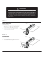
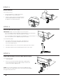
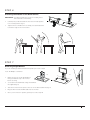
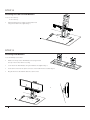
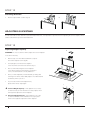
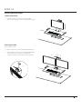
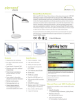
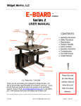
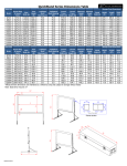
INSTA L L ATI O N I N ST R U C T I O N S
PA RT S R EQUIR ED
Single QuickStand Parts
A
A
(1) QuickStand Unit
B
(1) Base Plate
C
(1) Platform
D
(1) Palm Support
E
(1) VESA Plate
F
(6) M8 x 18 mm Flat Head Machine Screws
G
(4) M4 x 18 mm Pan Head Phillips
H
(4) M4 x 8 mm Pan Head Phillips
I
(4) VESA Spacer
B
D
Additional Parts for Dual Monitor QuickStand
J
(1) Dual Monitor Crossbar
K
(1) M6 x 22 mm Flat Head Machine Screws
L
(2) M5 x 18 mm Flat Head Machine Screws
M (2) VESA Plate
N
(8) M4 x 18 mm Pan Head Phillips
O
(8) M4 x 8 mm Pan Head Phillips
P
(8) VESA Spacer
E
C
J
Tools Required
M
3 mm Hex Key (supplied)
Box Knife
Hardware
4 mm Hex Key (supplied)
5 mm Hex Key (supplied)
6 mm Hex Key (supplied)
Tape Measure
#2 Phillips Screwdriver
F
K
G
L
H
N
I
O
Flat-Head Screwdriver
Customer Service: N America +1 800 400 0625 / International +353 (0)1 858 0910
P
www.humanscale.com
WARNING
Read all instructions carefully before installing this product or attempting to use it
This product contains a loaded mechanism that is under tension. Do not attempt to
remove or alter any part of this product or in any way modify or tamper with any
component of this product other than as set forth in these instructions. Failure to
comply with the instructions provided may result in property damage or serious injury.
Do not remove bracing box attached to QuickStand unit until your QuickStand is
fully assembled
ST EP 1
Remove Shipping Plate
Tools: 6 mm Hex Key
•
Lay the QuickStand unit on the work surface facing up
and unscrew the (2) M8 x 10 mm Cap Head Machine
Screws holding the Shipping Plate in place (fig. A)
•
Set aside the (2) M8 x 10 mm Cap Head Machine
Screws and the Washers for Step 3
A
ST EP 2
Attach Base Plate
Tools: 5 mm Hex Key
•
Secure the Base Plate in place using (6) M8 x 18 mm
Flat Head Machine Screws (fig. B)
B
3
ST EP 3
Attach Platform
Tools: 6 mm Hex Key
•
Ensure the Platform is equally spaced from
the Base Plate on either side (fig. C)
•
Using the (2) M8 x 10 mm Cap Head Machine
Screws and the Washers from step 1, secure
the Platform to the QuickStand unit
Platf
orm
Base
Plate
C
ST EP 4
Measure Work Surface Depth
IMPORTANT: Please check the depth of your work surface
- If you are installing a QuickStand with a Large Platform, your QuickStand
is pre-set to attach to a 29” (750 mm) deep work surface
-
If you are installing a QuickStand with a Small Platform, your QuickStand
is pre-set to attach to a 23” (600 mm) deep work surface
D
Tools: Measuring Tape
•
The distance between the front edge of the Platform to
the inside face of the Base Clamp must be equal to the
work surface depth (fig. D)
•
If the Base Clamp is in the correct position, please proceed to step 6
•
If the Base Clamp needs to be adjusted, please proceed to step 5
ST EP 5
Adjust Base Clamp for Correct Work Surface Depth
Tools: Measuring Tape
5 mm Hex Key
•
Loosen or remove the (4) M8 x 10 mm Pan Head Machine
Screws and slide/reposition the Base Clamp to achieve the
correct work surface depth (fig. E)
NOTE: If you will be installing the Grommet Mount/Bolt-through
base instead of the clamp, please refer to the Grommet Mount/Boltthrough kit instructions now.
4
E
ST EP 6
Attaching QuickStand to the Work Surface
IMPORTANT: Your QuickStand unit is heavy. If needed, please
have assistance when lifting.
•
Carefully lift your QuickStand unit from its horizontal position
to its vertical position (fig. F)
•
Tighten the two thumbscrews to clamp your QuickStand unit
to the back edge of the work surface
F
ST EP 7
Mounting Single Monitor
If you are installing a dual QuickStand unit please proceed to Step 8
Tools: #2 Phillips Screwdriver
G
•
Make sure the top of the VESA Plate is
facing towards the top of the monitor
before securing
•
Screw down the VESA Plate using the hardware
kit supplied (fig. G)
•
Slide the monitor into the quick-connector on the QuickStand unit (fig. H)
•
Plug the Power Cord and DVI Cable into the monitor
•
Once your monitor is in position, please proceed to Step 10
H
5
ST EP 8
Attaching Crossbar for Dual Monitors
Tools: 3 mm Hex Key
4 mm Hex Key
•
Attach Dual Monitor Crossbar to QuickStand unit
using the hardware kit supplied (fig. I)
I
ST EP 9
Attaching Dual Monitors
Tools: #2 Phillips Screwdriver
J
•
Make sure the top of the VESA Plates are facing towards
the top of the monitor before securing
•
Screw down the VESA Plates using the hardware kit supplied (fig. J)
•
Slide each monitor into the quick-connector on the Dual Monitor Crossbar (fig. K)
•
Plug the Power Cord and DVI cable into each monitor
K
6
ST EP 10
Secure Palm Support
•
Peel off sticker backing from Palm Support and place down
in your desired position on the front edge of the Platform (fig. L)
L
ST EP 11
Attaching USB Devices
Tools: Flat-Head Screwdriver
•
Using a Flat-Head Screwdriver if needed, remove cable cover by tilting out from the bottom (fig. M)
•
Route USB cables from keyboard and mouse into cable bracket (fig. N)
•
Carefully pull cable slack through bracket until cable heads are set within. Wrap remaining cable slack around bracket (fig. O)
•
Replace cable bracket cover (fig. P)
M
N
O
P
7
ST EP 12
Removing Brace Box
•
Remove tape and lift out box. (fig. Q)
Q
ADJUSTING QUICKSTAND
In order to be able to raise and lower your QuickStand with ease, it is important to spend some time adjusting the tension adjuster which
can be located in the top of the QuickStand unit
ST EP 13
Adjusting Weight Capacity
R
WARNING: Do not use a Power Drill to adjust the tension adjuster
Tools: 6 mm Hex Key
•
Remove top cover from QuickStand unit to expose
the tension adjuster screw (fig. R)
•
Slowly begin to turn the tension adjuster
screw clockwise to increase the tension (fig. S)
•
We recommend turning the tension adjuster
screw 10 revolutions at a time before checking to
see if your QuickStand is correctly balanced
•
Once you have adjusted your QuickStand, try raising and
lowering a few times until it fluidly adjusts. Your QuickStand
should stay where you set it
•
If you need to make further adjustments,
please follow these steps again
+ Increase Weight Capacity – If the platform is too heavy
to raise but easy to lower and does not stay in place when
raised, please adjust the tension adjuster
–
8
Decrease Weight Capacity – If the platform is too easy
to raise but difficult to lower and does not stay in place
when lowered, please adjust the tension adjuster
S
ST EP 14
Adjusting Monitor Height
SINGLE QUICKSTAND
•
Hold each side of your monitor and manually
raise or lower until it is in the correct position (fig. T)
T
DUAL QUICKSTAND
Tools: 6 mm Hex Key
•
Remove top cover of the carriage assembly (fig. V)
•
Slowly begin to turn the monitor height adjustment
screw clockwise to raise the monitors and
counter-clockwise to lower the monitors (fig. W)
W
V
9
ST EP 15
Adjusting Monitor Tilt
+15º
SINGLE AND DUAL QUICKSTAND
•
Hold the top and bottom of your monitor
and manually adjust the monitor tilt until the
desired angle is achieved (fig. X)
X
-5º
ST EP 16
Adjusting Monitor Orientation
SINGLE AND DUAL QUICKSTAND
•
Hold each side of your monitor and
manually turn the monitor until the desired
orientation of either landscape or portrait
is achieved (fig. Y)
ST EP 17
Correctly Setting Up Your Workstation
SINGLE AND DUAL QUICKSTAND
•
Adjust the platform until the keyboard
is at or just below elbow height
•
If needed, manually adjust the monitor up or down until
the top line of text on the screen is at eye level
10
±90º
Y
HSQSI1114
Customer Service: N America +1 800 400 0625 / International +353 (0)1 858 0910
www.humanscale.com