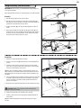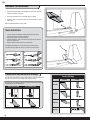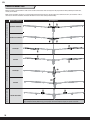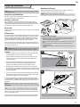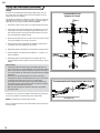
1
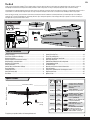
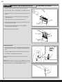
Ka-8 Instruction Manual / Bedienungsanleitung Manuel d’utilisation / Manuale di Istruzioni EN NOTICE All instructions, warranties and other collateral documents are subject to change at the sole discretion of Horizon Hobby, Inc. For up-to-date product literature, visit www.horizonhobby.com and click on the support tab for this product. Meaning of Special Language: The following terms are used throughout the product literature to indicate various levels of potential harm when operating this product: NOTICE: Procedures, which if not properly followed, create a possibility of physical property damage AND little or no possibility of injury. CAUTION: Procedures, which if not properly followed, create the probability of physical property damage AND a possibility of serious injury. WARNING: Procedures, which if not properly followed, create the probability of property damage, collateral damage, and serious injury OR create a high probability of superficial injury. WARNING: Read the ENTIRE instruction manual to become familiar with the features of the product before operating. Failure to operate the product correctly can result in damage to the product, personal property and cause serious injury. This is a sophisticated hobby product. It must be operated with caution and common sense and requires some basic mechanical ability. Failure to operate this Product in a safe and responsible manner could result in injury or damage to the product or other property. This product is not intended for use by children without direct adult supervision. Do not use with incompatible components or alter this product in any way outside of the instructions provided by Horizon Hobby, Inc. This manual contains instructions for safety, operation and maintenance. It is essential to read and follow all the instructions and warnings in the manual, prior to assembly, setup or use, in order to operate correctly and avoid damage or serious injury. Age Recommendation: Not for children under 14 years. This is not a toy. Safety Precautions and Warnings As the user of this product, you are solely responsible for operating in a manner that does not endanger yourself and others or result in damage to the product or the property of others. • • • • Always keep a safe distance in all directions around your model to avoid collisions or injury. This model is controlled by a radio signal subject to interference from many sources outside your control. Interference can cause momentary loss of control Always operate your model in open spaces away from full-size vehicles, traffic and people. Always carefully follow the directions and warnings for this and any optional support equipment (chargers, rechargeable battery packs, etc.). Always keep all chemicals, small parts and anything electrical out of the reach of children. • • • • • • • • • • • • • • Always avoid water exposure to all equipment not specifically designed and protected for this purpose. Moisture causes damage to electronics. Never place any portion of the model in your mouth as it could cause serious injury or even death. Never operate your model with low transmitter batteries. Always keep aircraft in sight and under control. Always use fully charged batteries. Always keep transmitter powered on while aircraft is powered. Always remove batteries before disassembly. Always keep moving parts clean. Always keep parts dry. Always let parts cool after use before touching. Always remove batteries after use. Always ensure failsafe is properly set before flying. Never operate aircraft with damaged wiring. Never touch moving parts. Charging Warnings The Battery Charger included with your aircraft is designed to safely balance and charge the Li-Po battery. CAUTION: All instructions and warnings must be followed exactly. Mishandling of Li-Po batteries can result in a fire, personal injury, and/or property damage. • • • • • • • 2 By handling, charging or using the included Li-Po battery, you assume all risks associated with lithium batteries. If at any time the battery begins to balloon or swell, discontinue use immediately. If charging or discharging, discontinue and disconnect. Continuing to use, charge or discharge a battery that is ballooning or swelling can result in fire. Always store the battery at room temperature in a dry area for best results. Always transport or temporarily store the battery in a temperature range of 40–120º F (5–49º C). Do not store battery or aircraft in a car or direct sunlight. If stored in a hot car, the battery can be damaged or even catch fire. Always charge batteries away from flammable materials. Always inspect the battery before charging and never charge damaged batteries. Always disconnect the battery after charging, and let the charger cool between charges. • • • • • • • • • Always constantly monitor the temperature of the battery pack while charging. ONLY USE A CHARGER SPECIFICALLY DESIGNED TO CHARGE LI-PO BATTERIES. Failure to charge the battery with a compatible charger may cause fire resulting in personal injury and/or property damage Never discharge Li-Po cells to below 3V under load. Never cover warning labels with hook and loop strips. Never leave charging batteries unattended. Never charge batteries outside recommended levels. Never attempt to dismantle or alter the charger. Never allow minors to charge battery packs. Never charge batteries in extremely hot or cold places (recommended between 40–120° F or 5–49° C) or place in direct sunlight. EN The Ka-8 Thank you for purchasing the ParkZone® Ka-8 sailplane. Many a full-scale pilot has taken their first single-seat sailplane flight at the controls of a Ka-8. Its friendly flight characteristics and impressive thermal performance make it the perfect next step for newly licensed pilots eager to stretch their wings. The ParkZone Ka-8 sailplane brilliantly captures the grace of this pre-composite era beauty. Like the full-scale Ka-8, it delivers a relaxing flying experience free of any bad habits. It can be launched using a Hi-Start, off a slope or behind a tow plane. The Z-Foam™ construction offers durability as well as easy repairs. Before you launch, though, you need to take a few minutes and read this manual. In addition to assembly instructions, you’ll find helpful tips on installing the optional E-flite® Servoless Payload Release, aerotowing, Hi-Start, slope soaring and operation of the Schempp-Hirth style of spoilers. It’s all here to make your first flight and every one after the best it can be. Box Contents Includes Table of Contents Battery Charging................................................................................. 4 Transmitter and Receiver Binding........................................................ 5 Battery Installation .............................................................................. 5 Voltage Regulator and Receiver Arming............................................... 6 Wing Assembly and Installation ........................................................... 7 Horizontal Tail Installation ................................................................... 8 Clevis Installation ................................................................................ 8 Control Horn and Servo Arm Settings .................................................. 8 Decal Installation ................................................................................ 9 Preflight Checklist ............................................................................... 9 Center of Gravity (CG) ......................................................................... 9 Dual Rates .......................................................................................... 9 Control Direction Test ........................................................................ 10 Flying Tips and Repairs ..................................................................... 11 Servoless Tow Release Installation .................................................... 14 Post Flight Checklist ......................................................................... 15 AMA National Model Aircraft Safety Code .......................................... 15 Troubleshooting Guide ...................................................................... 16 Limited Warranty .............................................................................. 17 Warranty and Service Contact Information ........................................ 18 FCC Information ................................................................................ 18 Compliance Information for the European Union ................................ 18 Replacement Parts............................................................................ 67 Optional Parts ................................................................................... 67 Specifications 88.6 inches (2.25m) Installed Installed 41.0 inches (1.7m) Sold Installed Separately Sold Installed Separately Sold Included Separately Weight: 27.7 oz (785 g) Sold Included Separately Sold Sold Separately Separately (2) Aileron Servos (PKZ1080) (1) Rudder Servo (1) Elevator Servo, (1) Spoiler servo (PKZ1090) Voltage Regulator: 2–3 cell LiPo regulator, 5.5V (EFLA120) Receiver: Spektrum™ AR610 6-Channel DSM2®/DSMX® Full range or park flyer sport receiver (SPMAR610) Battery: 7.4V 2S 1300mAh 20C Li-Po (EFLB13002S20) Battery Charger: 2-cell DC Balancing Li-Po charger (EFLC3125) Recommended Transmitter: Full-Range 4-Channel (or more) 2.4GHz with Spektrum™ DSM2®/DSMX® technology. To register your product online, visit www.parkzone.com 3 EN Battery Charging Your aircraft comes with a DC balancing charger and 2S Li-Po battery. You should only charge your battery with the included charger. Never leave the battery and charger unattended during the charge process. Failure to follow the instructions properly could result in a fire. When charging, ensure the battery is on a heat-resistant surface. Charge the flight battery while assembling the aircraft. Install the fully charged battery to perform control tests and binding. Charger Specifications • • Input power: 10-14V Charges 2-cell Li-Po packs with a minimum capacity of 1300mAh. DC Li-Po Balancing Charger Features • Balances and Charges 2-cell lithium-polymer battery packs • LED charge status indicator • 12V accessory outlet input cord Purchase optional 12V adapters (HBZ6513 or HBZ4747) to power your charger more conveniently. 7.4V 2S 1300mAh Li-Po battery (EFLB13002S20) • Maximum charge rate 1C (1.3 amps) The E-flite 2S Li-Po battery pack features a balancing lead that allows you to safely charge your battery pack when used with the included ParkZone Li-Po balancing charger. CAUTION: The balance connector must be inserted into the correct port of your charger prior to charging. The Battery Charging Process 1. Charge only batteries that are cool to the touch and are not damaged. Look at the battery to make sure it is not damaged e.g., swollen, bent, broken or punctured. 2. Insert the charger into the appropriate power supply (12V accessory outlet). 3. Connect the balancing lead of the battery to the charger port. 4. The LED will flash during charging. 5. The LED will glow solid when the battery is fully charged (approximately 1 hour). 6. Always disconnect the battery from the charger immediately upon completion of charging. The LED will turn off. CAUTION: Overcharging a battery can cause a fire. CAUTION: Only use a charger specifically designed to charge a Li-Po battery. Failure to do so could result in fire causing injury or property damage. CAUTION: Never exceed the recommended charge rate. NOTICE: If using a battery other than the included Li-Po battery, refer to your battery manufacturer’s instructions for charging. 4 EN Transmitter and Receiver Binding “Binding” is the process of programming the receiver to recognize the GUID (Globally Unique Identifier) code of a single specific transmitter. You need to bind your chosen Spektrum™ DSM2®/DSMX® technology equipped aircraft transmitter to the receiver for proper operation (please visit www.bindnfly.com for a complete list of compatible transmitters). CAUTION: When using a Futaba® transmitter with a Spektrum DSM® module, you must reverse the throttle channel and rebind. Refer to your Spektrum module manual for binding and failsafe instructions. Refer to your Futaba transmitter manual for instructions on reversing the throttle channel. Binding Procedure Reference Table 1. Read the transmitter instructions for binding to a receiver (location of transmitter’s Bind control). 2. Make sure the transmitter is powered OFF. 3. Move the transmitter controls to neutral (flight controls: rudder, elevators and ailerons) or to low positions (throttle, throttle trim).* 4. Install a bind plug in the receiver bind port. 5. Connect the flight battery to the voltage regulator. 6. The receiver LED will begin to flash rapidly. 7. Power ON the transmitter while holding the transmitter bind button or switch. Refer to your transmitter’s manual for binding button or switch instructions. 8. When the receiver binds to the transmitter, the light on the receiver will turn solid. 9. Remove the bind plug from the bind port. Bind Plug Installation 10. Safely store the bind plug (some owners attach the bind plug to their transmitter using two-part loops and clips). 11. The receiver should retain the binding instructions received from the transmitter until another binding is done. * If you encounter problems, follow the binding instructions and refer to the transmitter troubleshooting guide for other instructions. If needed, contact the appropriate Horizon Product Support office. Battery Installation 1. Push the button (A) into the fuselage to release the latch. 2. Lift the back of the hatch and pull up to remove the hatch. 3. Apply hook and loop tape on the back of the battery (B) as shown. A 4. Install the fully charged battery (C) in the battery compartment with approximately 1 inch (25mm) of the battery projecting from the compartment. See the Adjusting the Center of Gravity instructions for more information. 5. Reinstall the hatch. Push the rear of the hatch to ensure the latch is fully engaged. Battery Selection • • • We recommend the E-flite 1300mAh 7.4V 2S Li-Po battery (EFLB13002S20). If using another battery, the battery must be at least a 1300mAh battery. Your battery should be approximately the same capacity, dimensions and weight as the E-flite Li-Po battery to fit in the fuselage without changing the center of gravity a large amount. B C Alternative battery option (4- or 5-cell Ni-Cd or Ni-MH battery with switch harness) 1. Install the switch in an easily accessible location in the fuselage. 2. Secure the battery in the fuselage with hook and loop tape. 3. Insert the power output connector from the switch harness into the battery port or any open channel on your receiver NOTICE: Do not plug a 2S Li-Po or Li-Fe battery directly into your receiver or damage will result. The servos in this model are rated at 6 volts maximum. 5 EN Receiver Selection and Installation • • • • • Before installing the wing, install your full range receiver in the fuselage using hook and loop tape or double-sided servo tape. Connect the elevator and rudder servo to the appropriate channels of the receiver. Connect the aileron Y-harness to the aileron channel of the receiver. Connect the voltage regulator to the AUX 1 channel of the receiver prior to binding. Once bound, move the regulator to the BND port. Connect the spoiler extension into the throttle channel of the receiver. Voltage Regulator Selection and Installation Only use a voltage regulator or BEC with a 5–6 volt output. We recommend the E-flite battery (EFLB13002S20) and voltage regulator (EFLA120). • • • • Install the voltage regulator in the fuselage using hook and loop tape or double-sided servo tape. Secure the battery in the fuselage with hook and loop tape. Insert the power output connector from the regulator into the AUX 1 channel of your receiver prior to binding. Once bound, move the regulator to the BND port. To power on the receiver, connect a battery to the voltage regulator. Always unplug the battery from the voltage regulator when the aircraft is not in use. Voltage Regulator and Receiver Arming 1 Arming the voltage regulator also occurs after binding as previously described, but subsequent connection of a flight battery requires the steps below. CAUTION: Always disconnect the Li-Po battery from the aircraft receiver when not flying to avoid over-discharging the battery. Batteries discharged to a voltage lower than the lowest approved voltage may become damaged, resulting in loss of performance and potential fire when batteries are charged. 1. Power ON the transmitter and lower the throttle and throttle trim to their lowest settings. 2 2. Remove the battery hatch and install the fully charged battery in the battery compartment using the hook and loop strip, then connect the battery to the voltage regulator. 3. When a battery is connected to the voltage regulator, the built-in battery status LED will illuminate. Failsafe Failsafe positions are established when you bind your transmitter and receiver. If radio signal connection is lost between the transmitter and receiver, the receiver immediately moves the control surfaces to the failsafe positions. Before flight, ALWAYS confirm the failsafe functions as you expect. 3 LED Battery Indicator LED STATUS 2-CELL Li-Po Solid Battery is charged above 7.6V Flashing Recommend charging before flying Battery is between 6.6 and 7.6V No LED (connected battery) DO NOT FLY BEFORE CHARGING Battery is below 6.6V Monitor your aircraft battery’s voltage before and after flying by using a Li-Po Cell Voltage Checker (EFLA111, sold separately). 6 EN Wing Assembly and Installation IMPORTANT: Bind the aircraft to your transmitter before wing installation for easier spoiler adjustment. A Before flying, bind the aircraft to your transmitter again to correctly set failsafe. Assembly 1. Slide the wing tube (A) in the hole in the left wing. 2. Slide the other end of the wing tube into the hole in the right wing until both wings meet. Ensure the aileron servo wires exit the wing through the forward slot in the bottom of the wing as shown. B 3. Install the wing cover (B) on the top of the wing, aligning the 5 holes as shown. 4. Flip the wing assembly over and attach the right spoiler clevis (C) to the outermost hole in the servo arm (D). For more information about attaching the clevis, refer to the “Clevis Installation” section. Hemostats or needle nose pliers may be needed to connect the clevis. D C Installation 1. Remove the canopy hatch (F) from the fuselage. 2. Insert the servo connectors (G) through the hole in the fuselage (H) to the receiver. 3. Connect the aileron servos to the aileron Y-harness. The left and right servos can be connected to either side of the Y-harness. Insert the spoiler connector in the throttle port of the receiver. Tip: When using a transmitter capable of controlling separate ailerons, the aileron Y-harness is not required. If desired, connect the aileron servos to the AIL and AUX1 ports of the receiver. Set up aileron control accordingly in your transmitter. 4. Use the transmitter throttle to extend and retract the spoilers. Turn the wing as needed to adjust the spoilers. Disconnect and adjust the right spoiler clevis on the linkage so the spoilers extend equally and fully retract in response to the throttle. G H F I 5. Apply tape over the spoiler linkage channels on the underside of the wings. CAUTION: DO NOT crush or otherwise damage the wiring when attaching the wing to the fuselage. 6. Install the wing assembly to the fuselage using 3 screws (I). 7. Install the canopy hatch on the fuselage. When needed, disassemble in reverse order. Tip: We recommend removing the wing from the fuselage for storage or transport. 7 EN Horizontal Tail Installation A 1. Install the horizontal tail (A) in the slot (B) in the vertical tail. Ensure the elevator control horn faces down. 2. Secure the horizontal tail on the fuselage using a screw (C). 3. Attach the clevis to the elevator control horn (see instructions for clevis connection). When needed, disassemble in reverse order. B Clevis Installation • • • • Turn the clevis on the linkage to change the length of the linkage between the servo arm and the control horn. Pull the tube from the clevis to the linkage. Carefully spread the clevis, then insert the clevis pin into the desired hole in the control horn. Move the tube to hold the clevis on the control horn. After binding a transmitter to the aircraft receiver, set the trims and sub-trims to 0, then adjust the clevises to center the control surfaces. 1. 4. 2. 5. 3. 6. C Control Horn and Servo Arm Settings Factory Settings Horns Arms The table to the right shows the factory settings for the control horns and servo arms. Fly the aircraft at factory settings before making changes. After flying, you may choose to adjust the linkage positions for the desired control response. See the table below. More control throw Elevator Less control throw Rudder Ailerons Spoilers 8 EN Decal Installation All aircraft carry a unique alphanumeric string that identifies civil or military aircraft. Your ParkZone® Ka-8 sailplane includes two alphanumeric decal options. Option A (N15343) represents an aircraft registered in the U.S., while Option B (D54332) represents an aircraft registered in Germany. A Application 1. Ensure the fuselage is clean. 2. Lift a decal from a sheet and carefully apply it to the aircraft. 3. Rub out from the center of the self-adhesive decal to remove bubbles. B Preflight Checklist 1. 2. 3. 4. Charge the flight battery. Install the flight battery in the aircraft (once it has been fully charged). Make sure the linkages move freely. Perform the Control Direction Test with the transmitter. 5. 6. 7. 8. Adjust the flight controls and transmitter. Perform a radio system Range Check. Find a safe and open area. Plan flight for flying field conditions. Center of Gravity (CG) The CG location is 75mm back from the leading edge of the wing. Install the recommended flight battery with the end of the battery aligned with the rear edge of the foam battery shelf. Make sure the flight battery is secured using the hook and loop strap. IMPORTANT: Always adjust the location of components in the fuselage to achieve the recommended center of gravity. Do not fly your aircraft if the center of gravity is not at the recommended location. 75mm 2.95 inches back from the leading edge of the wing. Aircraft CG and weight is based on an E-flite 7.4V 1300mAh 20C battery (EFLB13002S20) installed. Dual Rates Your DSM2/DSMX full range transmitter features dual rates to help you select the amount of travel that you want from the control surfaces. High Rate Low Rate Aileron 17mm up/15mm down 12mm up/11mm down Elevator 16mm up/down 11mm up/down Rudder 32mm left/right 22mm left/right 9 EN Control Direction Test Move the controls on the transmitter to make sure the aircraft control surfaces move correctly and in the proper direction. After performing the Control Test, correctly set the failsafe. Make sure the transmitter controls are at neutral and the throttle and throttle trim are in the low position, then rebind the aircraft to your transmitter. If the receiver loses its link to the transmitter, the failsafe will drive the servos to these settings made at binding. Aircraft Reaction Up Elevator Command Aileron Down Elevator Command Stick Right Rudder Elevator Transmitter Command Stick Right Stick Left Spoilers Stick Left 10 Throttle Stick Down The spoilers deploy when the transmitter throttle is fully lowered. The spoilers retract when the throttle is fully advanced. Using a computerized radio (DX6i and up), you may adjust the throttle endpoints to deploy the spoilers as desired. EN Flying Tips and Repairs Consult local laws and ordinances before choosing a flying location. Maintenance and Storage NOTICE: This is not a high-speed sailplane. Avoid prolonged high speed dives or damage may result. Extreme and/or prolonged heat decreases the life of rubber cord. Store the assembly in a cool, dry place, loosely wound on a spool. Range Check your Radio System NOTICE: Avoid leaving the assembly in an automobile. After final assembly, range check the radio system with the aircraft. Refer to your specific transmitter instruction manual. d Win Choosing a Launch Area Fly in this area Your local AMA radio controlled aircraft flying field is the best location for flying. However, if you do not have access to such a field, many other open areas will work. Avoid possible damage to your launch system and aircraft by launching only in areas clear of brush, trees and other obstacles. 600 Hand Launch Hold the Ka-8 fuselage under the wing. Launch the sailplane into the wind with the wings level. feet (182 .8 m ) Stand here Hi-Start Launch A Hi-Start launch kit consists of elastic tubing connected to a tow line. A good Hi-Start launch propels a small sailplane 200–300 feet off the ground, ample height for seeking thermals. The E-flite Hi-Start (EFLA650, sold separately) includes a bright parachute to make it easier to find the end of the line and to align the Hi-Start with the wind in preparation for the next launch. You may need assistance to safely launch your aircraft using the Hi-Start. On your chosen flying field, anchor your Hi-Start the furthest point upwind so that you can launch into the wind. Hi-Start Precautionary Guidelines • Make sure the stake is securely anchored. Check throughout the day to make sure the stake is not loose. Reposition the stake if necessary to account for changing wind conditions. • During the launch, make sure there is no one between you and the anchor stake. • Do not over-stretch the rubber. Doing so can over-stress the airplane, causing wing failure. • Periodically check all knots. If the rubber or string shows wear, replace the assembly. CAUTION: Avoid driving a stake into buried utility lines or damage and injury could result. Contact local utility authorities for assistance if needed. Launching 1. Choose an anchor spot in firm soil and drive the stake at an approximate 45-degree angle to your chosen launch path (see image A). A Wind Hi-Start Stake 2. Slide the rubber loop through the open section of the stake. Pull on the assembly to ensure it is securely attached to the stake and the stake is secure in the ground. 3. Unroll the assembly downwind from the stake, ensuring there are no tangles or knots. Once your assembly is completely laid out (but not stretched), slowly walk away from the stake, stretching the rubber. 4. Walk approximately 120–150 ft (36–46 m) and attach the string loop to the Hi-Start hook on the bottom of your airplane. Keep a firm grasp on your Hi-Start and your aircraft. Ensure your transmitter and aircraft are powered on and bound together. 5. Toss the aircraft into the wind at a 30 degree upward angle (see image B). During launch, it may be necessary to use the transmitter for small corrections before the sailplane reaches soaring altitude. 45Û B 30Û In normal wind conditions, the Hi-Start will unwind to approximately 450 ft (137 m) and stretch an additional 100–120 ft (30–37 m). Increase or decrease the stretch distance according to wind strength. Stretch the Hi-Start less on windy days. NOTICE: Do not exceed 180 ft (55 m) when stretching the Hi-Start to launch your sailplane. Tip: For your first launches, elevator input should not be necessary. Use the rudder to keep the airplane straight and use the ailerons to keep the wings level during launch. After you become proficient at launching, apply approximately 1/4 up elevator to increase launch height, however, too much elevator may cause the airplane to stall. When the sailplane reaches its maximum launch altitude, the ring should fall from the hook. If the ring does not fall, fly upwind or tap the down elevator. Wind 45Û 11 EN Flying Tips and Repairs (continued) Towing Towing is only recommended for advanced pilots. While towing, be sure to fly in a large, open space. Also be sure that you have two pilots, one for the sailplane, and one for the towplane. Recommended Aircraft Alignment for Takeoff This sailplane is designed to be towed from a smooth runway by a sport plane (300 watt or greater), such as the E-flite® Apprentice® S. A tow line (approximately 40 feet (12.2 m) long) is available separately (PKZ6623). Wind 1. Position both aircraft near each other on the runway, facing into the wind. 2. Tie the tow line to the rear wing mount posts on an Apprentice S, or at the trailing edge of the wing on the towplane fuselage. Insert the loop of the other end of the tow line to the release mechanism under the nose of the Ka-8 (see Tow Release Installation section). 3. Space the aircraft apart so there is no slack in the tow line. If there is slack, it can result in damage to one or both of the aircraft. 40 ft (12.2 m) 4. Ensure that the tow line is resting above the towplane’s horizontal tail so the towplane can pull the sailplane into the air safely. 5. Quickly apply power to the towplane once both pilots are ready for takeoff. 6. Keep the towplane on the ground until the sailplane is 2–3 ft (0.9–1.2 m) above the towplane. 7. Slowly apply elevator to lift the towplane off of the ground. Be sure to keep the towplane under the sailplane until you have reached your release altitude. Tips for Towing • Continually communicate with the pilot of the towplane and make sure they are aware when you are having difficulty, or are releasing the tow line. • Ensure that you keep the sailplane’s wings level at all times. You should not try to turn the sailplane, but rather allow the tow plane to drag the sailplane around turns. • Avoid slack in the line while flying. Slack can cause the tow plane to abruptly pull the sailplane in unexpected directions. This can cause numerous problems and could result in a crash of one or both aircraft. • The tow release location makes the Ka-8 naturally rise behind the towplane without use of the elevator. Down elevator accelerates the sailplane and makes undesirable slack in the tow line. • Make only wide sweeping turns. Tight turns will result in the sailplane becoming unstable. If a problem occurs, the pilot of the sailplane should release the tow line from the nose of his sailplane so that both aircraft can be safely landed. NOTICE: Crash damage is not covered under warranty. If there is a break in the tow line, tie the ends together securely or replace the line when needed. 12 Recommended Aircraft Towing Positions When Flying 40 ft (12.2 m) EN Flying Tips and Repairs (continued) Flying Spoilers/Air Brakes Thermal Flying Your sailplane can ascend on thermals and other updrafts to prolong its flight far beyond the flight time one would expect. The Schempp-Hirth style of spoiler (air brake) on this aircraft gives you increased drag without the additional lift of flaps. A thermal is simply a column of rising warm air. Once you get your aircraft into the air using the Hi-Start or aero-tow, watch your aircraft for a response to thermals. In the same way, watch your aircraft for movement or rising. If the airplane randomly rolls on its own, it is likely that you only flew through the edge of the thermal, causing one side of the airplane to rise, rather than the entire airplane. Enter the thermal by turning your aircraft directly into it, circling to stay in the center of the thermal. Slow your forward speed by increasing up elevator trim so that your aircraft is moving just faster than stall (minimum sink speed). Make easy banking turns to find the area of highest lift (the thermal’s core). When you find the core of lift, tighten your turns to stay near this position. Sometimes thermals drift downwind. It is best that you search for thermals upwind, so that you can follow a thermal downwind if it is pushed downwind. With practice, you will find it easier to locate and anticipate the movement of thermals. Although thermals cannot be seen, you can see dust, insects or birds riding an updraft. Air movement of a thermal may be felt, so movement in an otherwise calm spot may show you the location of a nearby thermal. A shift in the wind (in a light breeze) can be airflow into a thermal. Thermals are generated by the sun heating darker ground objects more than surrounding surfaces. The dark object absorbs the sun’s heat, becoming warm and heating the air above it. The heated air rises and forms a column or funnel. Usually the base of the thermal is small. The updraft expands and decreases in speed as the air rises and cools. There are usually downdrafts around the updraft, as cooler air falls or moves less than the warm updraft. Thermals can vary in strength, rising at speeds from a few hundred to over a thousand feet per minute. Cooler downdrafts around a thermal are referred to as “sink.” Your aircraft can be pulled down by these downdrafts. Prevailing wind can aso bend or break a thermal from its heat source so that a warm air bubble travels downwind as it rises with little or no attendant downdrafts. Slope Soaring Finding a hill with directly oncoming winds is critical for an enjoyable slope soaring experience. The face of the hill needs to be flat or concave like a giant bowl to help concentrate lift. A convex hill (a hill with a protruding “bump”) will distribute lift and is not suitable for slope soaring. The windward side of the hill should not have trees, buildings, or other obstructions that can cause turbulence. Suitable slope soaring sites may be found surrounding valleys, in coastal areas or along mountain ridges, or may just be a random hill facing a prevailing wind. A small hill with an optimal shape and minimal wind will provide better lift than a large hill with a poor shape and higher wind speeds. Learning how to read the slope to understand where to expect lift and areas to avoid will lead to a bird-like understanding of how the air flows over hillsides. Winds for slope soaring are frequently seasonal and only flyable when conditions are favorable. How the hill channels the oncoming wind is critical to slope soaring. Part of selecting a slope soaring location needs to account for where you are going to land. A smooth grassy area on the top of the hill is optimal, but even locations on the front side of the hill with less of a slope and a smooth surface will suffice. Landing areas on the leeward side of the hill are not suitable. When slope soaring, launch into the wind from a location near the top of the hill. Always turn into the wind to avoid loss of airspeed. Turning toward the hill may result in a crash or loss of control. Slope lift can be found on the front side of the hill. The backside of the hill has dangerous turbulence and will cause a crash with most sailplanes. Flying on the backside of the hill is possible with DS (dynamic soaring) gliders, but this type of flying requires expert knowledge of slope soaring and specialized airframes. Do not attempt dynamic soaring with this glider. Landing approaches are typically done parallel to the hillside, allowing the pilot to approach right between the lift zone and the backside to land the glider without picking up airspeed. The spoilers (only on the upper surface of the wing) “spoil” or decrease lift for sections of the wing and increase drag. This allows you to descend at a steeper rate and land in smaller areas without gaining airspeed and allows you to bleed off energy more quickly. IMPORTANT: This aircraft has been designed so that deploying the spoilers does not affect any other control surface. On your transmitter, no mixes are required from the spoilers to other control surfaces. Landing Land into the wind. Due to the high lifting efficiency of the sailplane design, landing requires a large landing area clear of trees, buildings and cars. While on your downwind leg, remember that the sailplane glides much better than other aircraft. You may need to setup for landing lower and with a more shallow decent than you may be used to. As you are on approach for landing, ensure that the model is descending slowly, but also not accelerating. If the model is accelerating, it is likely that you will overshoot your projected landing area. Deploy the spoilers during landing to help the sailplane decelerate faster. Maintain this descent and speed, and, as the model nears the ground (approximately 6 inches (15 cm)), slowly apply a small amount of up elevator. The model should level out and fly parallel to the ground, decelerating further. Be sure the model does not climb. As it decelerates, keep flying the model parallel to the ground until it comes to rest gently on the landing gear. Battery Power Management Due to the aircraft having no motor and the small power needs of the sailplane, you may not know you have a low battery until the controls fail. We recommend setting a flight timer for 2 hours, if using a fully charged battery to prevent over discharging your battery, and potentially losing control of your aircraft. Before and after each flight, ensure the voltage regulator LED light is solid. If the LED is flashing or is not lit, immediately remove and recharge the battery. Monitor your aircraft battery’s voltage before and after flying by using a Li-Po Cell Voltage Checker (EFLA111, sold separately). When a Li-Po battery is discharged below 3V per cell, it will not hold a charge. Disconnect and remove the Li-Po battery from the aircraft after use to prevent trickle discharge. Charge your Li-Po battery to about half capacity before storage. During storage, make sure the battery charge does not fall below 3V per cell. LVC does not prevent the battery from over-discharge during storage. NOTICE: Repeated discharging below 3V per cell will damage the battery. IMPORTANT: Do not attempt to fly or operate your sailplane any longer than 2 hours on a battery until you are able to consistently judge your flight time for soaring conditions. NOTICE: Crash damage is not covered under warranty. NOTICE: When you are finished flying, never leave the aircraft in direct sunlight or in a hot, enclosed area such as a car. Doing so can damage the foam. Repairs Thanks to the Z-Foam™ construction of this aircraft, repairs to the foam can be made using virtually any adhesive (hot glue, regular CA, epoxy, etc). When parts are not repairable, see the Replacement Parts List for ordering by item number. For a listing of all replacement and optional parts, refer to the list at the end of this manual. NOTICE: Use of CA accelerant on your aircraft can damage paint. DO NOT handle the aircraft until the accelerant fully dries. 13 EN OPTIONAL Servoless Tow Release Installation (EFLA405, sold separately) 1. Remove the battery hatch from the fuselage using the latch button. 2. Under the fuselage, remove 2 screws (A) and the cover (B) from the nose. 3. Insert the connector of the servoless payload release (C) in the hole in the fuselage. 4. Install the optional servoless payload release (D) in the fuselage using 2 screws (E) as shown. B 5. Install the cover on the nose of the fuselage using 2 screws. 6. Use a pair of hemostats or needle nose pliers to pull the release connector from the nose up to the receiver. A 7. Insert the connector in an open channel of the receiver (GEAR is recommended for most transmitters). When needed, disassemble in reverse order. C D E Tow Line Connection G 1. Pull back the lever (F) on the side of the payload release to retract the pin (G). A small tool, such as a piece of wire may, be needed to pull back the lever. 2. Install the loop (H) of the tow line around the pin, then release the lever. 3. Ensure the pin is fully engaged to hold the tow line. F Tip: Before towing, use your transmitter switch to connect and release a tow line. NOTICE: DO NOT attempt to launch your Ka-8 using a High-Start connected to the tow release or a tow line connected to the High-Start hook. Incorrect use of connections can result in loss of control and damage to the aircraft. H 14 EN Post Flight Checklist 1. Disconnect the flight battery from the voltage regulator (Required for Safety and battery life). 2. Power OFF the transmitter. 3. Remove the flight battery from the aircraft. 4. Recharge the flight battery. 5. Repair or replace all damaged parts. 6. Store the flight battery apart from the aircraft and monitor the battery charge. 7. Make note of the flight conditions and flight plan results, planning for future flights. AMA National Model Aircraft Safety Code Effective January 1, 2011 A. GENERAL A model aircraft is a non-human-carrying aircraft capable of sustained flight in the atmosphere. It may not exceed limitations of this code and is intended exclusively for sport, recreation and/or competition. All model flights must be conducted in accordance with this safety code and any additional rules specific to the flying site. 1. Model aircraft will not be flown: (a) In a careless or reckless manner. (b) At a location where model aircraft activities are prohibited. 2. Model aircraft pilots will: (a) Yield the right of way to all man carrying aircraft. (b) See and avoid all aircraft and a spotter must be used when appropriate. (AMA Document #540-D-See and Avoid Guidance.) (c) Not fly higher than approximately 400 feet above ground level within three (3) miles of an airport, without notifying the airport operator. (d) Not interfere with operations and traffic patterns at any airport, heliport or seaplane base except where there is a mixed use agreement. (e) Not exceed a takeoff weight, including fuel, of 55 pounds unless in compliance with the AMA Large Model Aircraft program. (AMA Document 520-A) (f) Ensure the aircraft is identified with the name and address or AMA number of the owner on the inside or affixed to the outside of the model aircraft. (This does not apply to model aircraft flown indoors). (g) Not operate aircraft with metal-blade propellers or with gaseous boosts except for helicopters operated under the provisions of AMA Document #555. (h) Not operate model aircraft while under the influence of alcohol or while using any drug which could adversely affect the pilot’s ability to safely control the model. (i) Not operate model aircraft carrying pyrotechnic devices which explode or burn, or any device which propels a projectile or drops any object that creates a hazard to persons or property. Exceptions: • Free Flight fuses or devices that burn producing smoke and are securely attached to the model aircraft during flight. • Rocket motors (using solid propellant) up to a G-series size may be used provided they remain attached to the model during flight. Model rockets may be flown in accordance with the National Model Rocketry Safety Code but may not be launched from model aircraft. • Officially designated AMA Air Show Teams (AST) are authorized to use devices and practices as defined within the Team AMA Program Document (AMA Document #718). (j) Not operate a turbine-powered aircraft, unless in compliance with the AMA turbine regulations. (AMA Document #510-A). 3. Model aircraft will not be flown in AMA sanctioned events, air shows or model demonstrations unless: (a) The aircraft, control system and pilot skills have successfully demonstrated all maneuvers intended or anticipated prior to the specific event. (b) An inexperienced pilot is assisted by an experienced pilot. 4. When and where required by rule, helmets must be properly worn and fastened. They must be OSHA, DOT, ANSI, SNELL or NOCSAE approved or comply with comparable standards. B. RADIO CONTROL 1. All pilots shall avoid flying directly over unprotected people, vessels, vehicles or structures and shall avoid endangerment of life and property of others. 2. A successful radio equipment ground-range check in accordance with manufacturer’s recommendations will be completed before the first flight of a new or repaired model aircraft. 3. At all flying sites a safety line(s) must be established in front of which all flying takes place (AMA Document #706-Recommended Field Layout): (a) Only personnel associated with flying the model aircraft are allowed at or in front of the safety line. (b) At air shows or demonstrations, a straight safety line must be established. (c) An area away from the safety line must be maintained for spectators. (d) Intentional flying behind the safety line is prohibited. 4. RC model aircraft must use the radio-control frequencies currently allowed by the Federal Communications Commission (FCC). Only individuals properly licensed by the FCC are authorized to operate equipment on Amateur Band frequencies. 5. RC model aircraft will not operate within three (3) miles of any pre-existing flying site without a frequency-management agreement (AMA Documents #922-Testing for RF Interference; #923- Frequency Management Agreement) 6. With the exception of events flown under official AMA Competition Regulations, excluding takeoff and landing, no powered model may be flown outdoors closer than 25 feet to any individual, except for the pilot and the pilot’s helper(s) located at the flight line. 7. Under no circumstances may a pilot or other person touch a model aircraft in flight while it is still under power, except to divert it from striking an individual. This does not apply to model aircraft flown indoors. 8. RC night flying requires a lighting system providing the pilot with a clear view of the model’s attitude and orientation at all times. 9. The pilot of a RC model aircraft shall: (a) Maintain control during the entire flight, maintaining visual contact without enhancement other than by corrective lenses prescribed for the pilot. (b) Fly using the assistance of a camera or First-Person View (FPV) only in accordance with the procedures outlined in AMA Document #550. Please see your local or regional modeling association’s guidelines for proper, safe operation of your model aircraft. Federal Aviation Administration Prior to flying, contact your local or regional modeling organizations for guidance and familiarize yourself with the current local rules and FAA regulations governing model aviation in your location. More information about model aviation can be found at www.modelaircraft.org. The Federal Aviation Administration can be found online at www.faa.gov. 15 EN Troubleshooting Guide Problem Reduced flight time Aircraft will not Bind (during binding) to transmitter Aircraft will not connect (after binding) to transmitter Possible Cause Flight battery charge is low Completely recharge flight battery Flight battery damaged Replace flight battery and follow flight battery instructions Flight conditions may be too cold Make sure battery is warm before use Spoilers not fully retracted Center throttle trim and adjust clevises on spoiler servo so spoiler fully retracts Transmitter too near aircraft during binding process Move powered transmitter a few feet from aircraft, disconnect and reconnect flight battery to aircraft Aircraft or transmitter is too close to large metal object, wireless source or another transmitter Move aircraft and transmitter to another location and attempt binding again The bind plug is not installed correctly in the bind port Install bind plug in bind port and bind the aircraft to the transmitter Flight battery/Transmitter battery charge is too low Replace/recharge batteries Bind switch or button not held long enough during bind process Power off transmitter and repeat bind process. Hold transmitter bind button or switch until receiver is bound Transmitter too near aircraft during connecting process Move powered transmitter a few feet from aircraft, disconnect and reconnect flight battery to aircraft Aircraft or transmitter is too close to large metal object, wireless source or another transmitter Move aircraft and transmitter to another location and attempt connecting again Bind plug left installed in bind port Rebind transmitter to the aircraft and remove the bind plug before cycling power Aircraft bound to different model memory (ModelMatchTM radios only) Select correct model memory on transmitter Flight battery/Transmitter battery charge is too low Replace/recharge batteries Transmitter may have been bound using different DSM protocol Bind aircraft to transmitter Control surface does Control surface, control horn, linkage or servo damage not move Wire damaged or connections loose Controls reversed 16 Solution Replace or repair damaged parts and adjust controls Do a check of wires and connections, connect or replace as needed Transmitter is not bound correctly or the incorrect model was selected Re-bind or select correct model in transmitter Flight battery charge is low Fully recharge flight battery Regulator damaged Replace regulator Transmitter settings are reversed Perform the Control Direction Test and adjust the controls on transmitter appropriately EN Limited Warranty What this Warranty Covers Horizon Hobby, Inc. (“Horizon”) warrants to the original purchaser that the product purchased (the “Product”) will be free from defects in materials and workmanship at the date of purchase. What is Not Covered This warranty is not transferable and does not cover (i) cosmetic damage, (ii) damage due to acts of God, accident, misuse, abuse, negligence, commercial use, or due to improper use, installation, operation or maintenance, (iii) modification of or to any part of the Product, (iv) attempted service by anyone other than a Horizon Hobby authorized service center, (v) Product not purchased from an authorized Horizon dealer, or (vi) Product not compliant with applicable technical regulations. OTHER THAN THE EXPRESS WARRANTY ABOVE, HORIZON MAKES NO OTHER WARRANTY OR REPRESENTATION, AND HEREBY DISCLAIMS ANY AND ALL IMPLIED WARRANTIES, INCLUDING, WITHOUT LIMITATION, THE IMPLIED WARRANTIES OF NON-INFRINGEMENT, MERCHANTABILITY AND FITNESS FOR A PARTICULAR PURPOSE. THE PURCHASER ACKNOWLEDGES THAT THEY ALONE HAVE DETERMINED THAT THE PRODUCT WILL SUITABLY MEET THE REQUIREMENTS OF THE PURCHASER’S INTENDED USE. Purchaser’s Remedy Horizon’s sole obligation and purchaser’s sole and exclusive remedy shall be that Horizon will, at its option, either (i) service, or (ii) replace, any Product determined by Horizon to be defective. Horizon reserves the right to inspect any and all Product(s) involved in a warranty claim. Service or replacement decisions are at the sole discretion of Horizon. Proof of purchase is required for all warranty claims. SERVICE OR REPLACEMENT AS PROVIDED UNDER THIS WARRANTY IS THE PURCHASER’S SOLE AND EXCLUSIVE REMEDY. Limitation of Liability HORIZON SHALL NOT BE LIABLE FOR SPECIAL, INDIRECT, INCIDENTAL OR CONSEQUENTIAL DAMAGES, LOSS OF PROFITS OR PRODUCTION OR COMMERCIAL LOSS IN ANY WAY, REGARDLESS OF WHETHER SUCH CLAIM IS BASED IN CONTRACT, WARRANTY, TORT, NEGLIGENCE, STRICT LIABILITY OR ANY OTHER THEORY OF LIABILITY, EVEN IF HORIZON HAS BEEN ADVISED OF THE POSSIBILITY OF SUCH DAMAGES. Further, in no event shall the liability of Horizon exceed the individual price of the Product on which liability is asserted. As Horizon has no control over use, setup, final assembly, modification or misuse, no liability shall be assumed nor accepted for any resulting damage or injury. By the act of use, setup or assembly, the user accepts all resulting liability. If you as the purchaser or user are not prepared to accept the liability associated with the use of the Product, purchaser is advised to return the product immediately in new and unused condition to the place of purchase. Law These terms are governed by Illinois law (without regard to conflict of law principals). This warranty gives you specific legal rights, and you may also have other rights which vary from state to state. Horizon reserves the right to change or modify this warranty at any time without notice. WARRANTY SERVICES Questions, Assistance, and Services Your local hobby store and/or place of purchase cannot provide warranty support or service. Once assembly, setup or use of the Product has been started, you must contact your local distributor or Horizon directly. This will enable Horizon to better answer your questions and service you in the event that you may need any assistance. For questions or assistance, please visit our website at www.horizonhobby.com, submit a Product Support Inquiry, or call the toll free telephone number referenced in the Warranty and Service Contact Information section to speak with a Product Support representative. Inspection or Services If this Product needs to be inspected or serviced and is compliant in the country you live and use the Product in, please use the Horizon Online Service Request submission process found on our website or call Horizon to obtain a Return Merchandise Authorization (RMA) number. Pack the Product securely using a shipping carton. Please note that original boxes may be included, but are not designed to withstand the rigors of shipping without additional protection. Ship via a carrier that provides tracking and insurance for lost or damaged parcels, as Horizon is not responsible for merchandise until it arrives and is accepted at our facility. An Online Service Request is available at http:// www.horizonhobby.com/content/_service-center_render-service-center. If you do not have internet access, please contact Horizon Product Support to obtain a RMA number along with instructions for submitting your product for service. When calling Horizon, you will be asked to provide your complete name, street address, email address and phone number where you can be reached during business hours. When sending product into Horizon, please include your RMA number, a list of the included items, and a brief summary of the problem. A copy of your original sales receipt must be included for warranty consideration. Be sure your name, address, and RMA number are clearly written on the outside of the shipping carton. NOTICE: Do not ship LiPo batteries to Horizon. If you have any issue with a LiPo battery, please contact the appropriate Horizon Product Support office. Warranty Requirements For Warranty consideration, you must include your original sales receipt verifying the proof-of-purchase date. Provided warranty conditions have been met, your Product will be serviced or replaced free of charge. Service or replacement decisions are at the sole discretion of Horizon. Non-Warranty Service Should your service not be covered by warranty, service will be completed and payment will be required without notification or estimate of the expense unless the expense exceeds 50% of the retail purchase cost. By submitting the item for service you are agreeing to payment of the service without notification. Service estimates are available upon request. You must include this request with your item submitted for service. Non-warranty service estimates will be billed a minimum of ½ hour of labor. In addition you will be billed for return freight. Horizon accepts money orders and cashier’s checks, as well as Visa, MasterCard, American Express, and Discover cards. By submitting any item to Horizon for service, you are agreeing to Horizon’s Terms and Conditions found on our website http://www.horizonhobby.com/ content/_service-center_render-service-center. ATTENTION: Horizon service is limited to Product compliant in the country of use and ownership. If received, a non-compliant Product will not be serviced. Further, the sender will be responsible for arranging return shipment of the un-serviced Product, through a carrier of the sender’s choice and at the sender’s expense. Horizon will hold non-compliant Product for a period of 60 days from notification, after which it will be discarded. 17 EN Warranty and Service Contact Information Country of Purchase Horizon Hobby Horizon Service Center (Repairs and Repair Requests) United States of America Horizon Product Support (Product Technical Assistance) Sales United Kingdom Germany France China Service/Parts/Sales: Horizon Hobby Limited Horizon Technischer Service Sales: Horizon Hobby GmbH Service/Parts/Sales: Horizon Hobby SAS Service/Parts/Sales: Horizon Hobby – China Phone Number/Email Address servicecenter.horizonhobby.com/ RequestForm/ www.quickbase.com/db/ bghj7ey8c?a=GenNewRecord 888-959-2305 [email protected] 888-959-2305 [email protected] +44 (0) 1279 641 097 [email protected] +49 (0) 4121 2655 100 [email protected] +33 (0) 1 60 18 34 90 [email protected] +86 (021) 5180 9868 Address 4105 Fieldstone Rd Champaign, Illinois, 61822 USA Units 1–4 , Ployters Rd, Staple Tye Harlow, Essex, CM18 7NS, United Kingdom Christian-Junge-Straße 1 25337 Elmshorn, Germany 11 Rue Georges Charpak 77127 Lieusaint, France Room 506, No. 97 Changshou Rd. Shanghai, China 200060 FCC Information This device complies with part 15 of the FCC Rules. Operation is subject to the following two conditions: (1) This device may not cause harmful interference, and (2) this device must accept any interference received, including interference that may cause undesired operation. Compliance Information for the European Union Declaration of Conformity Declaration of Conformity (in accordance with ISO/IEC 17050-1) (in accordance with ISO/IEC 17050-1) No. HH2013050304 No. HH2013050303 Product(s): Item Number(s): Equipment class: Product(s): Item Number(s): Equipment class: PKZ Ka-8 Sailplane BNF PKZ6680 1 The object of declaration described above is in conformity with the requirements of the specifications listed below, following the provisions of the European R&TTE directive 1999/5/EC, EMC Directive 2004/108/EC and LVD Directive 2006/95/EC: EN 301 489-1 V1.9.2: 2012 EN301 489-17 V2.1.1: 2009 PKZ Ka-8 Sailplane PNP PKZ6675 1 The object of declaration described above is in conformity with the requirements of the specifications listed below, following the provisions of the EMC Directive 2004/108/EC: EN55022:2010 + AC:2011 EN55024:2010 EN60950-1:2006+A11:2009+A1:2010+A12: 2011 Signed for and on behalf of: Horizon Hobby, Inc. Champaign, IL USA May 03, 2013 EN55022:2010 + AC:2011 EN55024:2010 Signed for and on behalf of: Horizon Hobby, Inc. Champaign, IL USA May 03, 2013 Steven A. Hall Vice President Horizon Hobby, Inc. Steven A. Hall Vice President Horizon Hobby, Inc. Instructions for disposal of WEEE by users in the European Union This product must not be disposed of with other waste. Instead, it is the user’s responsibility to dispose of their waste equipment by handing it over to a designated collections point for the recycling of waste electrical and electronic equipment. The separate collection and recycling of your waste equipment at the time of disposal will help to conserve natural resources and ensure that it is recycled in a manner that protects human health and the environment. For more information about where you can drop off your waste equipment for recycling, please contact your local city office, your household waste disposal service or where you purchased the product. 18 IT Replacement Parts • Ersatzteile • Pièces de rechange • Pezzi di ricambio Part # | Nummer Numéro | Codice Description Beschreibung Description Descrizione PKZ6602 Decal Sheet: Ka8 Parkzone Ka8: Derkorbogen Planche de décalcomanies: Ka-8 Foglio con decalcomanie: Ka-8 PKZ6607 Replacement Wheel: Ka8 Parkzone Ka8 : Austauschbugrad Roue Ka-8 Ruota di ricambio Ka-8 PKZ6609 Spoiler: Ka8 Parkzone Ka8:Störklappen Aérofrein Ka-8 Aerofreno Ka-8 PKZ6612 Hatch W/Pilot: Ka8 Parkzone Ka8: Kabinenhaube m. Pilot Bulle avec pilote Ka-8 Capottina c/pilota Ka-8 PKZ6618 Plastic Covers Set: Ka8 Parkzone Ka8: Kunststoffabdeckungen Set de carénages en plastique Ka-8 Set coperchi in plastica Ka-8 PKZ6620 Wing Set: Ka8 Parkzone Ka8: Tragflächenset Paire d’ailes Ka-8 Set ala Ka-8 PKZ6621 Wing Tube: Ka8 Parkzone Ka8: Tragflächenverbinder Clé d’aile Ka-8 Tubo ala Ka-8 PKZ6622 Pushrod Set: Ka8 Parkzone Ka8: Gestänge Set Set de tringleries Ka-8 Set comandi Ka-8 PKZ6625 Horizontal Stab: Ka8 Parkzone Ka8: Höhenleitwerk Stabilisateur Ka-8 Stab orizzontale Ka-8 PKZ6667 Bare Fuselage: Ka8 Parkzone Ka8: Rumpf o. Einbauten Fuselage nu Ka-8 Solo fusoliera Ka-8 EFLA120 2-3 cell Lipo regulator 5.5v E-flite Spannungsregler 2-3S LiPo 5,5V Régulateur 2-3S Li-Po Regolatore 5,5V per 2-3 celle LiPo PKZ1080 rudder/elevator servo: Ka8 Parkzone SV80 Servo Servo de dérive/profondeur Ka-8 Servo timone/elevatore Ka-8 PKZ1081 ailerons servo: Ka8 Parkzone SV80 Servo mit langem Kabel Servo d’aileron Ka-8 Servo alettoni Ka-8 PKZ1090 spoiler servo: Ka8 Parkzone DSV130 Digitalservo MG Servo d’aérofrein Ka-8 Servo aerofreno Ka-8 EFLC3125 2-Cell DC Balancing Li-Po Charger 2S DC Balancing Ladegerät Chargeur équilibreur LI-Po DC 2S Caricabatterie per 2 celle LiPo con bilanciatore SPMAR610 AR610 6-Channel Sport DSM2/ DSMX Receiver Spektrum AR610 DSMX 6 Kanal Sport Empfänger 6-canali Sport DSM2/DSMX Récepteur AR610 6 voies DSM2/DSMX AR610 ricevitore Optional Parts • Optionale Bauteile • Pièces optionnelles • Pezzi opzionali Part # | Nummer Numéro | Codice Description Beschreibung Description Descrizione EFLA250 Park Flyer Tool Assortment, 5 pc E-flite Park Flyer Werkzeugsortiment; 5 teilig Assortiment d'outils park flyer, 5pc Park Flyer assortimento attrezzi, 5 pc EFLAEC202 EC2ˇ Battery Connector (2) E-flite EC2 Akkubuchse (2) Prise EC2 côté batterie (2) EFLAEC203 EC2 Device/Battery Connector E-flite EC2 Stecker / Buchse Prise EC2 côté contrôleur (2) EC2 Connettore batteria (2) EC2 Connettore apparecchiatura/ batteria 1.5A AC Alimentatore (solo USA) Pinze tipo coccodrillo: adattatore 12V per presa accendisigari HBZ1004 1.5A AC Power Supply (US Only) 1.5A AC Power Supply (US Only) Alimentation secteur 1.5A (USA uniquement) HBZ6513 Alligator Clip: 12V Lighter Adapter Krokodilklemme: 12 V Zigarettenanzünder Adaptateur 12V allume cigare/pinces croco EFLA111 Li-Po Cell Voltage Checker EFLA405 Servoless Payload Release PKZ6623 EFLA650 Tow line: Ka8 Hi-Start E-flite Li-Po Cell Volt Checker E-flite Servoloses Nutzlastabwurfsystem (Schleppkupplung) Parkzone Ka8: Schleppleine E-flite Hochstartset EFLC3025 Celectraˇ 80W AC/DC Multi-Chemistry Battery Charger E-flite 80W AC/DC Multi-Akku Ladege- Chargeur de batterie AC/DC rät - EU Celectra 80 W multi-types Caricabatterie per batteria multichimica 80 W c.a./c.c. EFLC3020 200W DC multi-chemistry battery charger E-flite 200W DC Multi-Akku Ladegerät Chargeur multiple DC 200W 200W DC Caricabatterie universale EFLC4010 Celectra 15VDC 250W Power Supply E-flite 15VDC 250W Netzteil - EU Alimentatore Celectra 15V c.c., 250 W DYN1405 LiPoCharge Protection Li-Po Charge Protection Bag, Large Dynamite Sac de charge Li-Po, grand modèle Bag groß LiPoCharge Protection Li-Po Charge Protection Bag, Small Dynamite Sac de charge Li-Po, petit modèle Bag klein Spektrum DX4e DSMX 4 Kanal Sender DX4e DSMX 4-Channel Transmitter ohne Empfänger Emetteur DX4e DSMX 4 voies Sacchetto protezione per carica LiPo, grande Sacchetto protezione per carica LiPo, piccolo DX5e DSMX 5 Kanal Sender Emetteur DX5e DSMX 5 voies DX5e DSMX 5-Channel Transmitter Spektrum ohne Empfänger DX5e DSMX Trasmettitore 5 canali DX6i DSMX 6-Channel Transmitter Spektrum DX6i DSMX 6-Kanal Sender Emetteur DX6i DSMX 6 voies DX6i DSMX Trasmettitore 6 canali DX7s DSMX 7-Channel Transmitter Spektrum DX7s DSMX 7 Kanal Sender Emetteur DX7s DSMX 7 voies DX7s DSMX Trasmettitore 7 canali DX8 DSMX 8-Channel Transmitter Spektrum DX8 DSMX 8 Kanal Sender Emetteur DX8 DSMX 8 voies DX8 DSMX Trasmettitore 8 canali DX18 DSMX 18-Channel Transmitter Emetteur DX18 DSMX 18 voies DX8 DSMX Trasmettitore 18 canali DYN1400 Spektrum DX18 DSMX 18 Kanal Sender Contrôleur de tension Li-Po Prova tensione celle LiPo Dispositif de largage sans servo Gancio rilascio senza servo Câble de remorquage Catapulte Cavo di traino Cavo elastico Alimentation Celectra CC 15 V 250 W DX4e DSMX Trasmettitore 4 canali 67 © 2013 Horizon Hobby, Inc. ParkZone, E-flite, Apprentice, Celectra, EC2, DSM, DSM2, DSMX, Z-Foam, Bind-N-Fly, Plug-N-Play and ModelMatch are trademarks or registered trademarks of Horizon Hobby, Inc. The Spektrum trademark is used with permission of Bachmann Industries, Inc. Futaba is a registered trademark of Futaba Denshi Kogyo Kabushiki Kaisha Corporation of Japan. All other trademarks, service marks and logos are property of their respective owners. www.parkzone.com PKZ6680, PKZ6675 Created 05/13 35800