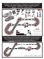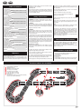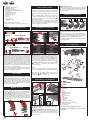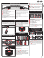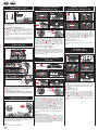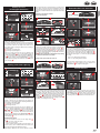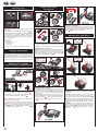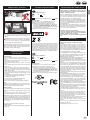
1
23612 Race de luxE Montage- und Betriebsanleitung Assembly and operating instructions Instructions de montage et d’utilisation Instrucciones de uso y montaje Instruções de montagem e modo de utilização Istruzioni per il montaggio e l’uso Montage- en gebruiksaanwijzing Monterings- och bruksanvisning Asennus- ja käyttöohjeet Montajse- og bruksanvisning Ősszeszerelési és használati útmutató Instrukcja obsługi i montażu Návod na montáž a pre prevádzkuo Návod na montáž a pro provoz Ръководство за монтаж и експлоатация Οδηγίες συναρμολόγησης και λειτουργίας Instrucţiuni de montaj şi de utilizare Monterings- og driftsvejledning 安装和使用说明 取扱説明書取扱説明書の内容は予 조립과 작동 방법 Montaj ve işletme kılavuzu Инструкция по монтажу и эксплуатации Verpackungsinhalt · Contents of package · Contenu du carton · Contenido de la caja · Conteúdo da embalagem · Contenuto della confezione · Verpakkingsinhoud · Innehållet i förpackningen Pakkauksen sisältö · Innholdet i pakningen · A csomag tartalma · Zawartość opakowania Obsah balenia · Obsah balení · Съдържание на опаковката · Περιεχόμενα συσκευασίας Conţinutul ambalajului · Emballageindhold · 包装内容 · 梱包内容 · 포장내용물 · Ambalaj içeriği · Содержимое картона 23612 Race de luxE 1x 1x 1x 1x 1x 1x SET 2x 2x 1x 146x C 4x 8x B CHANNEL 1x 11x A D 2x E V A h 3,7 150m 2x 4x 8x O 8x G H 8x K 8x L H I H A C D G L I F K D G H C K G M C C D B E H G C C D I P K D C I G K F M K H N I I C G M M M C C H G H CHANNEL SET F I D K K D I Q C H K L G D 1x 44 cm/17.32 inch 1x 60°/74 cm/29.13 inch 3x O 1x 180°/178 cm/70.08 inch I Produced under license of Ferrari Spa. FERRARI, the PRANCING HORSE device, all associated logos and distinctive designs are property of Ferrari Spa. The body designs of the Ferrari cars are protected as Ferrari property under design, trademark and trade dress regulations. 2x N 3x „Mercedes-Benz“, and the design of the enclosed product are subject to intellectual property protection owned by Daimler AG. They are used by Stadlbauer Marketing + Vertrieb GmbH under license. P 1x 240°/232 cm/91.34 inch 31x Q Ausbauvorschläge · Proposals for extension · Suggestions d‘extension · Propuestas de ampliación Propostas de expansão · Proposte di ampliamento · Uitbreidingsvoorstellen · Monteringsförslag Rakennelmaehdotuksia · Strekningsforslag · Kiépítési javaslatok · Propozycje rozbudowy Návrhy výstavby · Návrhy výstavby · Предложения за демонтаж · Προτάσεις επέκτασης Propuneri de asamblare · Udvidelsesforslag · 多项扩充建议 · 拡張提案 · 기타 조립 예 · Genişletme önerileri · Предложения по расширению CHANNEL SET 23612 + 2x 30353 + 30356 + 20601 2 Table of contents Safety instructions Declaration of Conformity Contents of package Technical advice for assembly Important Information Description Before first use Care of the battery Assembly instructions Guard Rails and Supports Electrical connection Car components Connections Control Unit Connecting the receiver Connecting the charging unit Charging the speed controllers Binding process Control elements Control Unit Encoding/programming of cars to the according speed controllers Preparation of start Points function Light function on/off Encoding/programming of Autonomous Car Encoding/programming Pace Car Display of position Autonomous and Pace Car Setting of the cars´ basic speed Setting of cars´ braking performance Setting fuel tank capacity Extended Pit Lane function Sound ON/OFF Reset function Energy-saving mode Replacement of double sliding contact and guide keel Height adjustment car chassis Changing the light board Maintenance and care Troubleshooting/Driving tips Technical specifications Requirement for FCC Part 15 Warnings 11 11 11 11 12 12 12 12 12 12 12 12 13 13 13 13 13 13 13 14 14 14 14 14 14 14 15 15 15 15 16 16 16 16 16 17 17 17 17 17 terwards. If you have any queries, please do not hesitate to contact our distributor or visit our websites: carrera-toys.com for cleaning, no solvents or chemicals. When it is not in use, store the track in a dry and dust-protected location, preferably in the original cardboard box. Please check the contents for completeness and possible transport damage. The packaging contains important information and should also be retained. We hope you will derive a lot of pleasure from your new Carrera DIGITAL 124 track. • Do not operate race track at face- or eye-level – risk of injury due to cars being catapulted off the track. • The toy is only to be connected to Class II equipment bearing the following symbol. Safety instructions • WARNING! Not suitable for children under 36 months. Danger of suffocation due to small parts which may be swallowed. Caution: risk of pinching caused by function. • WARNING! This toy contains magnets or magnetic components. Magnets attracting each other or a metallic object inside the human body may cause serious or fatal injuries. Seek medical attention immediately if magnets are swallowed or inhaled. • WARNING! Only allow children at least 8 years old to use the battery charger. Sufficient instruction must be given to enable the child to use the battery charger in a safe way and explain that it is not a toy and must not be played with. • The transformer is not a toy! Do not short-circuit the transformer’s connections! Note to parents: Regularly inspect the transformer for damage to the cable, plug or housing! Only operate the toy with recommended transformers! The transformer may no longer be used if it is damaged! Only operate the racetrack with a transformer! If play is interrupted for longer periods, it is recommended to separate the transformer from the power supply. Do not open transformer or speed controller housings! Important note to parents: Transformers and power supply units are not suitable to be used as toys. The use of such products needs to be constantly supervised by the parents. Welcome to the Team Carrera! These operating instructions contain important information regarding the assembly and operation of your Carrera DIGITAL 124 racetrack. Please read them carefully and keep them in a safe place af- • Do not place any metal parts onto the track to avoid short-circuits. Do not place the track in the immediate vicinity of delicate objects, as these could be damaged by cars hurled from the track. • Pull the plug before cleaning the racetrack! Only use a damp cloth • The toy and the charger must only be used with a transformer designed for toys. • If the supply cord is damaged, it must be replaced by the manufacturer, its service agent or similary qualified persons in order to avoid danger. Note: The vehicle may only be operated again in a completely assembled condition. Assembly may only be carried out by an adult. This appliance is not intended for use by persons (including children) with reduced physical, sensory or mental capabilities, or lack of experience and knowledge, unless they have been given supervision or instruction concerning use of the appliance by a person responsible for their safety. Children should be supervised to ensure that they do not play with the appliance. Instruct the child not to try and recharge non-rechargeable batteries because of the danger of explosion. Declaration of Conformity The company Stadlbauer Marketing + Vertrieb GmbH, hereby confirms that the product „2.4 GHz Wireless+“ complies with the fundamental requirements of Guideline 1999/5/EC (R&TTE). The Declaration of Conformity can be called up from the following address: carrera-toys.com • Regularly check the track, cars and charger for damage to cables, plugs and housings! Replace defective parts. • The car racetrack is not suitable for outdoor operation or operation in wet locations! Keep away from liquids. Welcome • Misuse of transformer can cause electrical shock. Contents of package 1 Mercedes-Benz SLS AMG GT3 “HEICO Motorsport, No. 1”, FIA GT3 European Championship 2012 1 Ferrari 599XX 11 Standard straights 1 Control Unit 1 Carrera DIGITAL 124 double lane change section (2 track parts) 1 Carrera DIGITAL 124 lane change section, left (2 track parts) Technical advice for assembly 1 2 3 4 5 6 7 8 Connecting track + Control Unit WIRELESS+ Receiver WIRELESS+ Twin charging station Lane change section left input Lane change section left output Double lane change section input Double lane change section output Infrared sensor: The infrared sensor MUST be located on the switch that functions as the entry rail (dark diode). 6 7 8 5 3 4 8 2 CHANNEL SET 1 11 8 2 1 1 2 1 Curves 1/60° WIRELESS+ Speed controllers WIRELESS+ Receiver WIRELESS+ Twin charging station LiPo rechargeable battery for speed controller Transformer Outside shoulders for curves Inside shoulders for curves Shoulder end sections Supports Guard rails Track section bolts Replacement contacts Accessories Care of the battery To make sure the battery performs well for as long as possible, the following points should be observed regarding its care and storage. InstructionsTrack length: 26.25 ft./ 8,0 m Dimensions when assembled: 11.75 x 6.20 f ft./ 358 x 189 cm • Before first using them, new batteries should always be charged fully. • With a fully-charged battery, continuous play is possible for up to eight hours. When the battery power is falling off, range of the speed controller will diminish. As soon as you notice this, the battery should be fully recharged. • If it is not to be used for an extended period, remove the battery and store the controller at room temperature (16-18 °C) in a dry place. To prevent a deep discharge of the battery, the stored battery should be charged every 2 to 3 months. 1 Carrera DIGITAL 124 Electrical connection 1 Assembly instructions Important Information Exclusiv 4 Supporting steep curves: Slanting supports of the right height are provided to support steep curves. Fix the nonadjustable supports at the beginning and end of the curves. Insert the heads of the supports in the round slots of the underside of the track. 1 Connect the transformer plug with the Control Unit. 4 Note: To avoid short-circuits and electrocution, the toy may not be connected using foreign devices, plugs, cables or other objects foreign to this toy. The Carrera Digital 124 car racetrack only works properly with an original Carrera Digital 124 transformer. The PC interface (PC Unit) may only be operated together with the original Carrera PC Unit. 2 Carrera DIGITAL 124 3 Car components Exclusiv 1 Please note that Exclusiv (analog system) and Carrera Digital 124/132 (digital system) involve two separate and completely independent systems. We hereby expressly indicate that both systems must be kept separate when setting up the track, i.e. no connecting rail from Exclusiv may be used together with the connecting rail and Black Box of the Carrera Digital 124/132, even if only one of the two connecting rails (Exclusiv connecting rail or Carrera Digital 124/132 connecting rail and Black Box) is attached to the current supply. Furthermore, no other Carrera Digital 124/132 components (switches, electronic lap counter, pit stop) may be built into an Exclusiv course, i.e. via analog operation. Non-compliance with the above information may result in damage or destruction of the respective Carrera Digital 124/132 components. In this case no warranty may be claimed. 1 + 2 + 3 Before assembling please insert the connecting clips in the track as shown in figure 1 . Stick tracks together on a flat base. Move the connecting clips according to figure 2 in direction of the arrow until they audibly snap in. The connecting clip may also be inserted later. The connecting clips can be removed into both directions by simply pressing down the clamped nose (see fig. 3 ). 14 3 7 Note: Carpeting is not a suitable foundation on which to build the track because of static charging, formation of fluff and ready inflammability. WIRELESS+ is the latest new cordless racetrack delight for Carrera DIGITAL124 and Carrera DIGITAL 132. The 2.4 GHz radio technology with frequency-hopping is free of interference and offers a range of up to 15 metres. Thanks to powerful lithium polymer rechargeable battery, continuous play for up to eight hours is possible and standby operation for over 80 days. WIRELESS+ offers cordless freedom for up to six drivers at the racetrack. 13 4 1 Guard rails: Guard rail mounts are fitted by tilting them upwards onto the verge of the track. 1 2 + 3 Supporting raised sections: The shank of the ball pivot is 2 3,7V hA 150m 1 12 11 2 3 5 10 Before first use Before first using the speed controller, the rechargeable battery supplied 2 must be inserted in the controller. Unscrew the battery compartment 1 on the underside of the speed controller. Connect the battery plug into the socket in the speed controller and put the battery in place in the compartment. Finally screw down the cover of the battery compartment again. The battery is part-loaded at the factory, but it should be charged completely before being used for the first time. 4 9 12 8 3 Guard Rails and Supports 1 6 3 The Position Tower is suitably connected to the shoulder connecting section F or to the Adapter Unit ; the latter can be positioned at any place within the racetrack. Description 3 2 15 4 Fastening: To fasten the track sections on a board, it is necessary to use the track section fasteners (Item no. 85209, not contained in the package). to be inserted into the square slots provided on the underside of the track. The supports can be made higher by using the extensions. The pedestal of the supports can be screwed to a base if required (screws not included). 1 2 3 4 5 6 7 8 9 10 11 12 13 14 15 Body Engine block Tyres Rear axle Rear axle receptacle including spacer plate Front axle Front axle mounting Board Central magnet Rear magnet Chassis Rocker arm including spring Guide keel with double sliding contact Center magnet retainer Fastening plate Note: vehicle construction depends on the model. The designation of the individual parts may not be used as order numbers. 3 Connections Control Unit To bind the second speed controller, follow the same procedure. Press the “SET” button 2 on the receiver twice, until the figure 2 appears 1 . Then press the binding button 3 on the second speed controller. 4 To display the address set for the speed controller, press once on the binding button 2 on the top of the speed controller. The LED 1 will then flash, according to the address set. 1 2 3 4 5 Connections (from left to right): 1 Connection for Lap Counter 30342 2 Connection for PC-unit or Lap Counter 30355 3 Connector 1 for speed controller, speed controller extension set or wireless+ receiver 4 Connector 2 for Wireless Tower 10108 5 Connector 3 for speed controller 6 Connector 4 for speed controller 7 Connection for DIGITAL 124 / DIGITAL 132 power supply General information on connectors 1-4: When a WIRELESS+ receiver is used, it must be plugged into connector 1. Optionally a Wireless Tower 10108 can be plugged into connector 2. When only the WIRELESS+ receiver is used, connector 2 is to be left empty. 6 Additional wired speed controllers may be plugged into connectors 3 and 4. Please note that these will use address 5 and 6 then. Control elements Control Unit Using the speed controller extension set 30348 it has to be plugged into connector 1. The cars´ addresses will be allocated as follows: • • • • Speed controller extension set = address 1, 3 and 4 connector 2 = address 2 connector 3 = address 5 connector 4 = address 6 Note: a combination of wireless and speed controller extension set is not possible! Connecting the receiver Charging the speed controllers Connect the receiver according to the symbol to either of the two sockets on the control unit which are marked Tower 1 and Tower 2. For operating six WIRELESS+ speed controllers only one 2.4 GHz receiver is required. Before first being used, the WIRELESS+ speed controllers should be fully charged. Place the speed controllers in the charging station and switch on the control unit. While the unit is charging, the LEDs 1 on the speed controllers will flash. When charging is completed, the LEDs 1 will light up continuously. When using a lithium polymer rechargeable battery, it is possible to top up the speed controller at any time. 1 1 2 3 4 5 6 7 8 4 3 5 6 2 7 1 8 On/off switch Switch for fuelling function Button to start the race / acknowledge programming Button for Pace Car / termination of programming Button for setting basic speed Button for setting braking performance Button for setting fuel tank capacity Programming button for cars General operating information Some buttons are assigned with different tasks. In order to set a function you need to use key combinations. Any programming steps can be cancelled with button 4 “ESC/PACE CAR″. You will find further details in the course of this manual. Encoding/programming of cars to the according speed controllers 1 4 CHAN If the speed controller is not actuated, it switches automatically after about 20 seconds into energy-saving mode. The speed controller can be reactivated by pressing the tappet or the lane-change button. 7 3 2 NEL 1 1 2 SET Symbols 5 6 Binding process 1 Connecting the charging unit 2 1 SET SET 2 4 1 CHANNEL SET 2 4 3 CHANNEL CHANNEL 3 Rear view of the control unit 3 1 The charging unit is connected at the rear of the control unit. To site the charging unit at any other place on the track, an adapter unit 30360 will be needed. 1x 8 7 2 3 1 To encode a car place it on the track and swich on the Control Unit. Press “Code” button once 8 , fig. 1 ; the first LED starts to light, fig. 2 . Then push lane-change-button once on the relevant speed controller, fig. 3 . In case the car is equipped with lights they will start to flash and the Control Unit´s LEDs 2-4 will light successively. Once encoding has been carried out the middle LED lights permanently (fig. 4 ) and the car is allocated to the speed controller. Note: This kind of encoding requires to only have the car on the racetrack which shall be encoded. Before the speed controller can be used to control the cars, it must be “bound” to the receiver. To do this, switch on the control unit. 1 The receiver indicates it is ready for operation by a revolving light signal in the segment display 1 . 2 Push the “SET” button 2 once until the figure 1 appears in the segment display 1 . The number shown is then the address of the car. Switch to the next address by further pressing the button. Now press the binding button 3 on the top of the speed controller. The speed controller signals a successful binding process with flashing of the LED, while the receiver indicates it by revolving lights in the segments. The binding process is now complete and the speed controller is ready for use. 13 Encoding/programming of Autonomous Car Preparation of start 1 42 3 5 6 2 1 1 1 2 2x 8 7 Display of position Autonomous and Pace Car Position 3Tower 30357 4 3 4 4 5 This Carrera Digital 124 vehicle ideally matches the Carrera track system scale 1:24. To ensure proper and continuous driving, slightly fan out the ends of the contact brushes 1 and bend them towards the track as per fig. 2 . Only the end of the contact brush should have contact to the track and may be cut off slightly in case of wear. Dust and abrasion should be removed from track material and sliding contacts from time to time. 5 150 100 200 50 0 During operation small car parts as spoilers or mirrors may get off or brake due to being original detailed parts of the car model. To avoid this it is possible to remove them before operation. 250 SPEED + CLICK 5 300 1 Note: This kind of encoding requires having only the car on the track which is to be encoded. The programming of the Autonomous Car will be maintained unless the car is not being recoded. The Autonomous Car is always displayed with address 7 in combination with the Position Tower. 1 3 2 7 3 5 Switch on the Control Unit, place the car to be encoded on the track and press „Code“ 8 twice, fig. 1 . The first two LEDs at the Control Unit start to light, fig. 2 . Now push the lane-change button at the speed controller, fig. 3 ; LEDs 3-5 will light successively. Wait until the middle LED lights again, fig. 4 . Activate the speed controller´s tappet until the car has reached the desired speed. Now push lane-change button again, fig. 5 . Autonomous Car´s encoding is completed now. Points function 2 6 4 1 + 2 Optimally setting up the grinders: 2 6 1 8 2 1 7 8 (only in combination with Position Tower #30357) The position of the Autonomous Car (address 7) and of the Pace 7 8 Tower. This funcCar6 (address 8) can be displayed at the Position tion can be activated at the Control Unit. Therefore switch off the Control Unit and keep the “BRAKE” button 6 pushed, fig. 2 , switch on the racetrack and release the “BRAKE” button again. By pushing the button again the function may be changed: 1 LED lights = no display 2 LEDs light = display at the Position Tower Set the function requested and confirm your choice via “START/ ENTER”. Setting of the cars´ basic speed 1 – 10 1 1 – 10 2 Encoding/programming Pace Car 2 3 3 4 Pit Lane 30356 4 3 2 4 1 1 3 2 5 5 6 3x 8 7 5 3 6 4 7 Light function on/off 3 sec. STOP The car programmed to the speed controller will have to come to a stop for at least 3 seconds before the light can be switched on or off by the push of the lane-change-button. Note: applies only to models fitted with lighting 14 5 150 100 200 50 0 250 6 6 8 4 5 1 Make sure that the car’s guide keel is located inside the track slot and that the double sliding contact is in contact with the current carrying track. Place the cars onto the connecting track. 2 When changing lanes, you must keep the button on the speed controller depressed until the car has passed the point. 5 1 2 SPEED + CLICK 300 (only in combination with Pit Stop Lane #30356) Switch on the Control Unit, place the car to be encoded on the track and press “Code″ 8 three times, fig. 1 . The first three LEDs at the Control Unit start to light, fig. 2 . Now push the lane-change button at the speed controller, fig. 3 ; LEDs 2-5 will light successively. Wait until the middle LED lights again, fig. 4 . Activate the speed controller´s tappet until the car has reached the desired speed. Now push lane-change button again, fig. 5 . The Pace Car´s encoding is completed now and the car enters the Pit Stop Lane. Note: This kind of encoding requires having only the car on the track which is to be encoded. The programming of the Pace Car will be maintained unless the car is not being recoded. The Pace Car is always displayed with address 8 in combination with the Position Tower. Extended Pace Car function After the Pace Car´s encoding has been completed it will automatically enter the Pit Lane during the first laps. In order to start the Pace Car please push the button “Pace Car” 4 once. The LEDs 2 and 3 at the Control Unit will light and the Pace Car will leave the Pit Lane. The Pace Car will now drive as long as the button „Pace Car“ is pushed again. LED 2 stops lighting and the car automatically enters the Pit Lane within the current lap. 3 2 1 The setting of the basic speed can be effected individually for one and/or several cars. The cars which are to be adjusted have to be 6 track. The setting can 7 be carried out on 810 levels positioned on the with the 5 LEDs indicating the different levels by flashing or permanent lighting. 1 1 LED lights = low speed 2 5 LEDs light = high speed Switch on the Control Unit, place the cars to be adjusted on the track and press “SPEED” 5 once. A certain number of LEDs will now light, showing the speed level last used. Push the “SPEED” button 5 as many times until you have reached the speed desired. Confirm by pressing “ENTER/START” 3 . A short running light and the lighting of the middle LED confirms completion of the setting, fig. 6 . drives slowlier and shows a lower braking effect; a car with an empty tank is “lighter”, drives faster and shows a higher braking effect. The current fuel tank capacity and the “fuel consumption” can only be displayed in combination with the Driver Display 30353 and Pit Stop 30356. Setting of cars´ braking performance 1 – 10 1 1 – 10 2 Extended Pit Lane function Refuelling of cars with Pit Lane 30356 and Driver Display 30353 Pit Lane 30356 Pit Lane 30356 Driver Display 30353 1 3 2 3 3 2 4 1 4 2 1 5 6 5 7 7 8 3 5 1 8 4 3 8 3 5 6 4 3 2 9 1 7 (only for cars operated with speed controllers) The setting of the braking performance can be effected individually 6 8 have for one and/or several cars. The cars7which are to be adjusted to be positioned on the track. The setting can be carried out on 10 levels with the 5 LEDs indicating the different levels by flashing or permanent lighting. 1 1 LED lights = low braking effect 2 5 LEDs light = high braking effect Switch on the Control Unit, place the cars to be adjusted on the track and press “BRAKE” 6 once. A certain number of LEDs will now light, showing the brake step last used. Push the “BRAKE” button 6 as many times until you have reached the braking performance desired. Confirm by pressing “ENTER/START” 3 . A short running light and the lighting of the middle LED confirms completion of the setting, fig. 6 . 2 5 6 7 1 – 10 6 4 • LED 1 = lap counting function deactivated • LED 1 + 2 = lap counting function activated Sound ON/OFF 2 12 4 4 1 3 2 6 5 8 3 8 2 1 (only for cars operated with speed controllers) The setting of the fuel tank capacity in combination with the Pit Lane 6 for all cars simultaneously. 7 (30356) is effected The setting8 can be carried out on 10 levels with the 5 LEDs indicating the different levels by flashing or permanent lighting. 1 1 LED lights = low fuel capacity 2 5 LEDs light = full tank 1 2 2 1 4 3 5 6 2 14 6 5 4 6 7 4 7 1 5 5 2 3 4 13 5 7 Select the desired setting and push or drive a car across the Pit Lane Sensor, fig. 5 . The settings will now be adopted. Push “START/ENTER” 3 for leaving the settings again. Driver Display 30353 1 3 2 Setting of tank capacity at the start of the race 11 3 3 (only in combination with Pit Lane 30356) It is possible to activate/deactivate the lap counting function in the 5 Pit Lane 30356 or Pit Stop Lane 30346 with the 6Pit Stop Adapter Unit 30361. Switch off the Control Unit, keep “SPEED” button 5 ) pushed, switch on Control Unit and release “SPEED” button 5 . By pushing the button again, 1 or 2 LEDs will light depending on the setting. 1 – 10 2 6 8 Setting fuel tank capacity 1 5 1 The car´s present tank capacity can be read via the bar display with 5 green and 2 red LEDs at the Driver Display. For refuelling drive your car into the Pit Lane across the refuelling sensor fig. 7 . The bar display now starts to flash, fig. 8 , and the car can be refuelled by keeping the lane-change button pushed. fig. 9 . The number of refuellings are indicated by flashing or lighting of the yellow LEDs, fig. 10 (also see Driver Display). Note: cars with an empty tank are disregarded for lap-counting in combination with Position Tower 30357. Pit Lane 30356 6 3 4 8 10 5 3 6 6 7 5 2 7 6 3 8 3 7 8 2 (only in combination with Pit Lane 30356 and Driver Display 30353) Irrespective of the basic setting of the tank capacity it is possible to individually set the 5 tank capacity for one 6 or several cars at7 the race´s start for the number of laps till the first pit stop. Push “START/ ENTER” once 3 ; the 5 LEDs at the Control Unit will light permanently, fig. 12 , and the Driver Display´s bar display will flash, fig. 13 . Clicking the lane-change button at the corresponding speed controller enables you to change the fill level, fig. 14 . 7 1 The confirmation sound when crossing the sensors and the key sound can be switched off. Switch off the Control Unit and keep the “START/ENTER” button 3 pushed, switch on the racetrack and 8 release “START/ENTER” 3 again. The acknowledgement sound for switching on the Control Unit cannot be switched off however. Switch on the Control Unit, place the cars to be adjusted on the track and activate the fuelling function by means of the slide switch 2 , fig. 3 . Press the “FUEL” button 7 once. A certain number of LEDs will now light, showing the fuel capacity last used. Push the “FUEL” button 7 as many times until you have reached the fuel capacity desired. Confirm by pressing “ENTER/START” 3 . A short running light and the lighting of the middle LED confirms completion of the setting, fig 6 . Extended fuelling function You can choose between 3 modes via the sliding switch 2 , fig. 3 : • OFF = cars don´t consume any “petrol” • ON = cars consume “petrol” • REAL = maximum speed depending on fuel tank capacity / cars consume “petrol”) (only in combination with Pit Lane 30356 or Pit Stop Lane 30346 and Pit Stop Adapter Unit 30361) When driving in “REAL-mode” the car with a full tank is “heavier”, 15 Height adjustment car chassis Reset function 1 2 1 8 2 4 3 5 6 2 2 1 7 8 1 3 7 3 2 1 7 2 To restore the Control Unit to factory settings the Control Unit offers a reset function. Switch off the 8 Control Unit and keep the “ESC/PACE CAR” 4 button pushed; switch on the ractrack and release the button again. All previous settings for speed, braking performance, tank fuel capacity, sound and lap counting will be restored to factory settings. The cars´ settings will remain unaffected by this measure unless they are placed on the racetrack. Factory settings: • speed = 10 • braking performance = 10 • tank capacity = 7 • sound = ON • display of position for Autonomous and Pace Car = OFF Energy-saving mode After 20 minutes of non-usage the Control Unit switches to energysaving mode and all displays such as Position Tower, Driver Displays and Startlight are turned off. To reactivate shortly press any speed controller´s tappet or push lane-change button at the speed controller or control key at the Control Unit. All settings will be kept. 3 4 Adjusting the central magnet If required, the central magnet can also be adjusted. Remove the magnet unit from the chassis in its entirety 1 , turn it horizontally by 180 degrees 2 and return it to the chassis. Then mount the magnet retainer 3 and restore all plug connections. Changing the light board 1 2 3 4 5 6 Before you can begin adjusting the chassis and the magnets it is necessary to detach the car body from the vehicle. Remove the mounting screws on the underside of the car and lift off the car body. Adjusting the height of the front axle 1 Remove the two screws from the front axle mounting and detach the entire front axle including the mounting from the chassis. 2 Detach the mounting from the axle, turn it through 180 degrees 3 and insert the axle back into the mounting 4 . Now you can return the front axle and mounting unit to the chassis. 1 2 Replacement of double contact brushes and guide keel 1 2 3 4 7 5 3 4 In case the car is lifted, the rocker bar folds up slightly (fig. 1 ). For changing the guide keel or the double contact brushes the rocker bar can be folded up widely according to fig. 2 . 3 For changing the guide keel and the double contact brushes the guide keel should be removed first. 4 Afterwards both double contact brushes can be removed and changed. Please take care that in stage one the upper contact brush 4 a is only pulled out partly and in stage two the double contact brush is pulled out completely with the contact brush 4 b For inserting please proceed the same way. 16 Adjusting the height of the rear axle To simplify the procedure, carefully detach the plug connection between the motor and the circuit board 1 . Remove the two screws from the motor block unit and detach the magnet retainer from the chassis. Now remove the two rear screws and detach the entire motor block 2 . Turn the motor block around and remove the two screws from the rear axle mounting. Remove the spacer plates and the rear axle unit including the mounting 3 . To adjust the height, place the spacer plate in the motor block 4 and tighten the screws of the rear axle unit. 5 . 1 ATTENTION! Depending on the model, the light boards might be screwed tight. Front light: To change the light boards unscrew the car’s upper part from the chassis. Unscrew the front axle according to fig. 1 and remove the cables between the front light and the car board (fig. 2 ). Slightly bend down the catch hook (fig. 3 ) and pull up the light board. Insert the light board (fig. 4 ), until the catch hook latches in. Screw in the front axle and fit the cables together according to their colours. Rear light: Remove the cables between the rear light and the car board according to fig. 5 Slightly bend down the catch hook (fig. 6 ) and pull up the light board. Insert the light board until the catch hook latches in (fig. 7 ) and fit the cables together according to their colours. Maintenance and care Technical specifications Requirement for FCC Part 15 Warning: Changes or modifications not expressly approved by the party responsible for compliance could void the user’s authority to operate the equipment. 1 Output voltage: Toy transformer 18 V 54 VA Lithium polymer rechargeable battery: 3,7 150mAh Electricity modes: 1.)Operating mode = cars are operated via speed controllers 2.)Idle mode = speed controllers not activated, no game 3.)Stand-by mode = after approx. 20 minutes idle mode the connecting section switches to stand-by mode. LED flashes at long intervals. CURRENT CONSUMPTION < 0,5 watt / 0,5w By operating the speed controller the stand-by mode is finished, the racetrack returns to idle-mode again. 4.)Off-state = power supply unit disconnected from mains supply 2 To ensure a proper operation of the motor-racing circuit, all racetrack components should be regularly cleaned. Pull the plug prior to cleaning. 1 Racetrack: Keep the track surface and track slots clean with a dry cloth. Do not use any solvents or chemicals for cleaning. When it is not in use, store the racetrack in a clean and dust-protected location, preferably in the original cardboard box. 2 Car check: Clean axle and wheel bearings, pinion gears, gearwheels and bearings and lubricate using a resin- and acid-free grease. You can use a toothpick or similar as aid. Regularly check the condition of sliding contacts and tyres.. Troubleshooting Driving tips Troubleshooting: In case of any malfunctions, please check the following: • Has the connection to the power supply been established correctly? • Have transformer and speed controllers been connected correctly? • Are the track connections faultless? • Are the racetrack and track slots clean and free of any foreign objects? • Are the sliding contacts in order and do they make contact with the track slot? • Are the cars correctly coded to the according speed controller? • The track‘s current feed will be switched off automatically for 5 seconds, if there is an electrical short circuit: this will be notified by audible and visual signals. • Are the cars placed on the track in running direction? In case of non-functioning push the running direction switch which is on the car´s bottom. • Is the adapter unit correctly installed facing the direction of travel? • Is the speed controller battery properly connected? • Is the battery fully charged? • Does the LED on the controller flash while charging? • Is the speed controller bound to the receiver? • Has the speed controller got a duplicate address assignment? Note: During operation small car parts as spoilers or mirrors may get off or brake due to being original detailed parts of the car model. To avoid this it is possible to remove them before operation. Driving technique: • You can drive fast along the straight track but you should brake before the curve and then accelerate again when coming out of the curve. • Do not fasten or block the vehicles when the motor is running: overheating or damage to the motor could result otherwise. Note: When using track systems which are not manufactured by Carrera the existing guide keel has to be replaced by the special guide keel (#85309). While using the Carrera crossing (#20587) or high banked curve 1/30° (#20574) slight driving noise might occur which is due to the full-scale genuineness and does not affect flawless operation. All Carrera spare parts are available in the webshop: carrera-toys.com Delivery exclusively to Germany, Austria, Netherlands, Belgium and Luxembourg. Note: This equipment has been tested and found to comply with the limits for a Class B digital device, pursuant to Part 15 of the FCC Rules. These limits are designed to provide reasonable protection against harmful interference in a residential installation. This equipment generates, uses and can radiate radio frequency energy and, if not installed and used in accordance with the instructions, may cause harmful interference to radio communications. However, there is no guarantee that interference will not occur in a particular installation. If this equipment does cause harmful interference to radio or television reception, which can be determined by turning the equipment off and on, the user is encouraged to try to correct the interference by one or more of the following measures: • Reorient or relocate the receiving antenna. • Increase the separation between the equipment and receiver, • Connect the equipment into an outlet on a circuit different from that to which the receiver is connected. • Consult the dealer or an experienced radio/TV technician for help. Warnings This device is marked by “selective sort throught” symbol related to sort through domestic, electric and electronic, waste. This means the product must be treated by a specialized “sorting/collecting” system in accordance with European directive 2002/96/CE, to reduce the impact upon environment. For more precise information, please contact your local administration. Electronical product which are not going through special collecting, are potentially dangerous for environment and human health, b ecause of dangerous substance. Output voltage: Toy transformer 18 V 54 VA Lithium polymer rechargeable battery: 3,7 150mAh Electricity modes: 1.)Operating mode = cars are operated via speed controllers 2.)Idle mode = speed controllers not activated, no game 3.)Stand-by mode = after approx. 20 minutes idle mode the connecting section switches to stand-by mode. LED flashes at long intervals. CURRENT CONSUMPTION < 0,5 watt / 0,5 w By operating the speed controller the stand-by mode is finished, the racetrack returns to idle-mode again. 4.)Off-state = power supply unit disconnected from mains supply Guidelines and warnings about using the LiPo battery/ batteries: LiPo rechargeable batteries are much more sensitive than the traditional alkaline or NiMh rechargeables. For this reason all instructions and warnings must be scrupulously observed. Incorrect treatment of LiPo rechargeable batteries may cause a fire. In handling, charging and using the LiPo battery/batteries supplied, you take over all responsibility for the risks attached to lithium batteries. • Non-rechargeable batteries must not be recharged! For recharging batteries, only the charging cradle supplied may be used. If this instruction is disregarded, there is a risk of fire which may endanger your health and/or cause damage to property. NEVER use any other charging unit! • Rechargeable batteries may only be recharged under adult supervision. When charging, never leave the battery unattended. When you recharge the battery, you should always be in the vicinity to keep watch on the process so that you can react to any possible problem. • If the battery swells or deforms during either discharge or charging process, stop the process immediately. Remove the battery as fast and as carefully as possible and place it on a safe and open area away from any flammable materials, and keep it under observation for at least 15 minutes. If you continue to charge or discharge a battery which has already started to swell or deform, there is danger of fire! Even at the slightest sign of swelling or deforming, the battery must be taken out of service. • The battery supplied must be charged in a safe place away from flammable materials. • Store the battery at room temperature (16 - 18 °C) in a dry place. Do not expose the battery to direct sunlight or any other sources of heat. Temperatures over 50 °C are generally to be avoided. • Always recharge the battery after use to avoid the possibility of its becoming deep discharged. When it is not in use, recharge the battery from time to time, say every 2-3 months. Failure to observe the methods of handling described above may lead to defects. • When changing batteries do not use any sharp or pointed objects or tools. Avoid damaging the protective foil around the battery at all costs. • When replacing defective batteries, only the recommended battery types may be used. Damaged or unusable batteries are hazardous waste, and must be disposed of accordingly. • Never throw batteries, rechargeable or otherwise, on the fire or expose them to high temperatures. This may cause a fire or an explosion. • The electrolyte and electrolyte vapour in the LiPo batteries are hazardous to health. Always avoid direct contact with electrolyte. If electrolyte makes contact with skin, eyes or other parts of the body, it must immediately be washed out or off with plenty of fresh water and a doctor must be consulted. • Rechargeable batteries are not toys and must not fall into the hands of children. Keep batteries inaccessible to children. • The connector clips / battery connections must never be shortcircuited! • The toy is only to be operated with a transformer or power pack designed for use with toys! • The transformer / the power pack is not a toy! 17 carrera-toys.com 7.23.12.15.00 · 08/2013 Stadlbauer Marketing + Vertrieb GmbH · Rennbahn Allee 1 · 5412 Puch / Salzburg · Austria