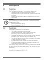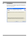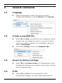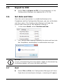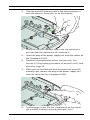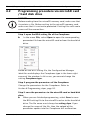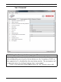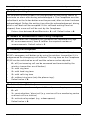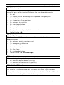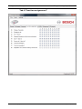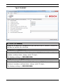
1
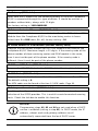
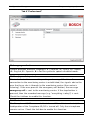
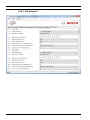
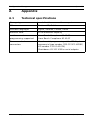
Configuration Manager 970.129b | V2 | 2014.05 en User Manual Configuration Manager Table of Contents | en 3 Table of Contents 1 Description 4 1.1 Features 4 1.2 Functions 4 2 Installation 5 3 General commands 6 3.1 Language 6 3.2 Create a new BPA file 6 3.3 Revert to factory settings 6 3.4 Print 6 3.5 Export to CSV 7 3.6 Set date and time 7 3.7 Exit 7 4 Programming via microSD card / hard disk drive 8 4.1 Installing the microSD memory card 8 4.2 Programming procedure via microSD card / hard disk drive 10 5 Programming via serial connection 11 5.1 Serial connection 11 5.2 Getting started 11 5.3 Programming procedure via serial connection 12 5.4 Firmware reflash 12 5.5 Manual firmware reflash 14 5.6 How to do with older Carephones 15 6 Programming steps 16 A Appendix 33 A.1 Technical specifications 33 A.2 APN codes 34 Bosch Security Systems User Manual 970.129b | V2 | 2014.05 4 en | Description 1 Description 1.1 Features Configuration Manager The Configuration Manager is a standalone software for – reading/writing the device parameters of Bosch Carephones 6X via serial connection, microSD card or hard disk drive – updating the firmware of Bosch Carephones 6X via serial connection. NOTICE! The programming via serial connection is supported at Bosch Carephones 6X from: 1.2 – Bosch Carephone 61 A2.02 – Bosch Carephone 62 A0.07 Functions The following information can be edited: – Call targets, protocols and media type – General configuration, such as radio transmission monitoring, activity monitor parameters, etc. – Extended configuration, such as waiting time for repeated emergency calls, activation of service button, etc. – Function assignment, which allows assigning a call number to each individual call trigger. – IP/GSM configuration, related to IP and GSM features – RF detector programming data, allowing assigning a call trigger to the wireless detectors. The settings can be saved into a CSV file, facilitating the upload of these settings into other applications. The settings can also be printed. microSD is a trademark of SD-3C, LLC. 970.129b | V2 | 2014.05 User Manual Bosch Security Systems Configuration Manager 2 Installation | en 5 Installation Download the MSI file package from www.boschsecurity.com. Store the file on your computer, double-click it and follow the steps of the setup wizard. Bosch Security Systems User Manual 970.129b | V2 | 2014.05 6 en | General commands Configuration Manager 3 General commands 3.1 Language Select the language in which you wish to see the Configuration Manager: click on Settings then Language. 3.2 Create a new BPA file Select File and New, a new BPA file for Carephones will be created. You can temporarily name it as you wish, but as soon as you want to upload it to a Carephone, you must name it settings.bpa. 3.3 In the menu Settings, Select the Carephone type. Revert to factory settings Select File and Factory settings, all the parameters in the Configuration Manager are reverted to the factory settings of the Carephone type. 3.4 Print Select File and Print, all the parameters in the Configuration Manager are sent to your default printer. 970.129b | V2 | 2014.05 User Manual Bosch Security Systems Configuration Manager 3.5 General commands | en 7 Export to CSV Select File and Export to CSV, all the parameters in the Configuration Manager are exported to a CSV file. 3.6 Set date and time Once the serial connection is established between the Carephone and the Configuration Manager, you can set the date and time values. The Configuration Manager will take the current date and time of the computer running it. 1. In the menu Serial, select Set date and time. 2. The Configuration Manager updates the date and time into the Carephone, and displays a confirmation message: NOTICE! A reset, disconnecting the main power supply or disconnecting the battery power, will erase the date and time. 3.7 Exit Select File and Exit, the Configuration Manager will close. If you have not saved your changes, a warning will appear. Bosch Security Systems User Manual 970.129b | V2 | 2014.05 8 en | Programming via microSD card / hard disk drive 4 Configuration Manager Programming via microSD card / hard disk drive NOTICE! Before you program the Carephone 61/62, you must be familiar with all of the unit's functions. Programming is specifically intended for trained users. Correct programming of the Carephone 61/62 is important for the full function of the unit. Make sure to always read the existing configuration before changing the values of the programming steps. 4.1 Installing the microSD memory card The Carephone 61/62 can be equipped with a microSD memory card to perform a fast and easy programming. NOTICE! Use a microSD memory card of 32 GB capacity or lower. 1. Remove the plug of the power supply unit from the socket 2. Open the top cover of the unit to access to the connection on the Carephone 61/62. compartment. The location of the microSD port is indicated in the following diagram: 970.129b | V2 | 2014.05 User Manual Bosch Security Systems Configuration Manager 3. Programming via microSD card / hard disk drive | en 9 Take the microSD memory card in the hand and place it with the contacts facing you, as on the drawing. 4. Insert the microSD memory card in the slot and push it until you feel the mechanism has clutched it. 5. Insert the plug of the power supply unit from the socket on the Carephone 61/62. 6. Perform the programming action that you wish. See Section 4.2 Programming procedure via microSD card / hard disk drive, page 10. 7. When you are finished and wish to remove the microSD memory card, remove the plug of the power supply unit from the socket on the Carephone 61/62. 8. To disengage it from the slot, simply push on the end of the microSD memory card and gently pull it out. Bosch Security Systems User Manual 970.129b | V2 | 2014.05 10 en | Programming via microSD card / hard disk drive 4.2 Configuration Manager Programming procedure via microSD card / hard disk drive NOTICE! Before reading from the microSD memory card, make sure that it contains a file. Before writing to the microSD memory card, make sure that it is not write-protected. Existing files with same names will be overwritten. Step 1: open the BPA setting file of the Carephone In the menu File, select Open to open the corresponding parameter file from the microSD card or from the hard disk drive. Based on the BPA setting file, the Configuration Manager identifies and displays the Carephone type in the lower right corner of the window. In this case, you cannot change the setting Carephone type. Step 2: program the parameters of the Carephone Change the parameters for the Carephone. Refer to Section 6 Programming steps, page 16. Step 3: save the parameters to the microSD card or hard disk drive When you are finished programming, select Save to save the BPA setting file to the microSD card or to the hard disk drive. The file name must always be settings.bpa. If you change the name of the file, then the upload of the parameter update into the Carephone will malfunction. 970.129b | V2 | 2014.05 User Manual Bosch Security Systems Configuration Manager Programming via serial connection | en 5 Programming via serial connection 5.1 Serial connection 11 The programming via serial connection is supported at Bosch Carephones 6X from: – Bosch Carephone 61 A2.02 – Bosch Carephone 62 A0.07 For Bosch Carephones 6X that do not support programming via serial connection, the commands Read Parameters and Write Parameters are disabled. You will also get an error message inviting you to update the Carephone. See Section 5.6 How to do with older Carephones, page 15. 5.2 Getting started Establish the serial connection In the menu Settings, select the COM Port to be used. Connect the Carephone 6X to its power supply. Connect the Carephone 6X to the computer running the Configuration Manager. – Use the Bosch serial programming cable APD 9 poles (commercial type number CRS-CP-SPC-APD9P, SAP number F.01U.140.074). If needed, the USB to serial adapter Brainboxes model US-101 can be recommended. The Configuration Manager now detects the Carephone and displays the information related: version and build, as well as the Carephone type in the lower right corner of the window. In this case, you cannot change the setting Carephone type. Bosch Security Systems User Manual 970.129b | V2 | 2014.05 12 en | Programming via serial connection 5.3 Configuration Manager Programming procedure via serial connection Once the Carephone is connected to its power supply and to the computer running the Configuration Manager via the serial cable, you can start programming directly the Carephone. Step 1: read the parameters from the Carephone In the menu Serial, click on Read Parameters. The Configuration Manager reads all the parameters from the Carephone and displays them in the different tabs. Step 2: program the parameters of the Carephone Change the parameters for the Carephone. Refer to Section 6 Programming steps, page 16. Step 3: write the parameters to the Carephone When you are finished programming, click on Write Parameters. The parameters are now sent to the Carephone via serial connection. 5.4 Firmware reflash The Configuration Manager must first detect the Carephone and display the version and build. See Section 5.2 Getting started, page 11. Step 1: launch the firmware reflash interface In the menu Serial, select Firmware reflash. 970.129b | V2 | 2014.05 User Manual Bosch Security Systems Configuration Manager Programming via serial connection | en 13 The Carephone 6X Reflash interface opens: Step 2: select the firmware file Click on the browse button and select the Motorola S19 firmware file. Make sure that the firmware file corresponds to the type of Carephone 6X that you are about to reflash. You have the possibility to keep the user audio announcement message. If so, tick the check-box. Step 3: start the firmware reflash Click on Reflash on the Carephone 6X Reflash interface. The firmware is sent to the Carephone: Bosch Security Systems User Manual 970.129b | V2 | 2014.05 14 en | Programming via serial connection Configuration Manager CAUTION! Do not disconnect the Carephone until the firmware update is finished! 5.5 Manual firmware reflash If the firmware reflash was interrupted, you must proceed with a manual firmware reflash. Step 1: launch the manual firmware reflash interface In the menu Serial, select Manual firmware reflash. The Manual Firmware Reflash interface opens: CAUTION! Make sure that the Carephone is connected to its power supply and to the computer running the Configuration Manager via the serial cable. Do not disconnect it until the manual firmware reflash is finished! 970.129b | V2 | 2014.05 User Manual Bosch Security Systems Configuration Manager Programming via serial connection | en 15 Step 2: bridge the Carephone 6X Open the Carephone 6X that needs a manual firmware reflash, as when replacing the battery. Refer to the user manual of the Carephone 6X. Connect the bridge, using a small slotted screwdriver: Step 3: start the manual firmware reflash Click on Connect on the Manual Carephone 6X Reflash interface. The Carephone is now reconnected to the Configuration Manager. The Carephone 6X Reflash interface opens. To finish reflashing the firmware, proceed as in Section Step 2: select the firmware file, page 13. 5.6 How to do with older Carephones Firmware update Before starting to program a Carephone that does not support programming via serial connection, you must first make a firmware update to get: – for a Bosch Carephone 61: version A2.02 or newer – for a Bosch Carephone 62: version A0.07 or newer Proceed as in Section 5.4 Firmware reflash, page 12. Bosch Security Systems User Manual 970.129b | V2 | 2014.05 16 6 en | Programming steps Configuration Manager Programming steps Programming a Carephone 61/62 with the Configuration Manager consists of entering values for the individual steps, numbered 01 to 129. NOTICE! According to the Carephone type, programming steps may not be visible and their values may change. Tab 1 "General" 970.129b | V2 | 2014.05 User Manual Bosch Security Systems Configuration Manager Programming steps | en 17 03. Radio jamming The Carephone 61/62 sends a technical message to the monitoring centre when a radio signal from another device disturbs it. Check the tick-box to enable this function. 25. Radio transmission monitoring The Carephone 61/62 can monitor the wireless transmitters that are assigned. The wireless transmitters send a signal to the Carephone 61/62 at regular intervals. A failure message is sent to the monitoring centre if the Carephone 61/62 does not receive this signal at least once a week. Check the tick-box to enable this function. 28. Call forwarding It is possible for the monitoring centre, if it supports this functionality, to command the Carephone 61/62 to forward the current call to a new destination using a specified protocol. You can allow the Carephone 61/62 to use the specified protocol or force it to use telephone protocol. This function is only possible with protocols RB2000E (target 0), CPC (target 3) and RBIP (target 9). Choose between: – 0 = forwarding to another number, 1 = forwarding to a telephone. 30. Device number When an emergency call is made, this number is sent to the monitoring centre. The number can be up to 12 digits long. Numbers 0000, 9998, 9999 and 999999 may not be used. Default value is 1248. 31. Sign in / sign out To specify whether the sign in or sign out of the activity monitor will initiate a call to a call recipient. Check the tick-box to enable this function. 32. Call progress tones audible You can choose to hear the call progress tones when the Carephone makes a call. Check the tick-box to enable this function. Bosch Security Systems User Manual 970.129b | V2 | 2014.05 18 en | Programming steps Configuration Manager 33. Speak / Listen command audible You can choose to hear the commands when the Carephone switches between speak and listen in half-duplex mode. Check the tick-box to enable this function. 40. Activity monitor hours and minutes The time for the activity monitor can be set between 15 minutes and 31 hours in steps of 15 minutes. – Enter the number of hours (example: 24 for 24 hours) in the first field. – Enter the number of minutes: 0 for 0 min, 1 for 15 min, 2 for 30 min and 3 for 45 min. It is also possible to program an automatic activation of the sign-out status. To activate the special feature for passive alarms, enter 4 for 0 min, 5 for 15 min, 6 for 30 min and 7 for 45 min. In this case, any intrusion alarm will be silent. Programming 0 - off and 0 (0 hours and 0 minutes) deactivates the activity monitor. Programming 99 means the time frame is set by the monitoring centre or through an SD card. This can only be used if the unit gets regularly real-time clock updates from a monitoring center. 100. Scheduler for the activity monitor You set up a scheduler for the activity monitor, with 2 time slots during which the activity monitor is active. Select, in 15 minutes intervals: start time 1, end time 1, start time 2 and end time 2. 62. Loudspeaker volume (Default, Max, Min) This step is used to program the default volume as well as the maximum and minimum settings. The default volume is the volume at which the monitoring centre communicates via the Carephone 61/62. Maximum setting is high volume. Minimum setting is low volume. Choose a value between 1 to 8 to program these three volumes. Default values are 4, 6 and 2 are shown first. 70. Automatic test call interval You can program the interval between automatic test calls from the Carephone 61/62 to the monitoring centre in days. In addition, there is a test call after power up or leaving programming mode, as well as a test call per randomization. Select from 1 to 28 days, 0 = off 970.129b | V2 | 2014.05 User Manual Bosch Security Systems Configuration Manager Programming steps | en 19 Tab 2 "Call Targets" Bosch Security Systems User Manual 970.129b | V2 | 2014.05 20 en | Programming steps Configuration Manager 11- 19 & 10 Destination number of the emergency call recipient You can enter here the destination number of the emergency call recipient, either a telephone number, or an IP address. 1) Enter the destination number of the emergency call recipient. In the case of a telephone number, register the call number as follows: You can add the following criteria in a telephone call number: B = Dial pause, D = Dial tone detection. In the case of an IP address, the call number should be written in numbers without dots, always 12 digits. Example: 192168010001. 2) After entering the call number, you must enter the protocol: – 0 = monitoring centre (protocols RB2000, RB2000E, ANT) – 1 = monitoring centre (TTnew+ protocol) – 3 = monitoring centre (CPC protocol) – 4 = to phone with acknowledgement – 5 = to phone without acknowledgement (only for direct call) – 7 = monitoring centre (BS8521 protocol) – 9 = monitoring centre (RBIP protocol) Settings 0 to 7 are designed to be used with the media PSTN. Setting 9 is designed to be used with the IP Module or GSM Module. 3) After entering the protocol, you can enter the media: – 0 = PSTN, related to the analogue interface of the Carephone. This also applies with a GSM Gateway or a DSL/cable modem. – 1 = LAN, related to the IP Module – 2 = GSM, related to the GSM Module The Carephone goes automatically to the next programming step and you can enter the next call number. When an emergency call is sent and if the call to the first call number is not successful, the Carephone will try the next numbers in the sequence 11 to 10. If the last number has been dialed unsuccessfully, the unit starts with the first number again and continues until it sends an emergency call successfully. A single programmed telephone number will be tried 12 times. The maximum number of dial attempts can be set. By default, it is set to 15 attempts. 970.129b | V2 | 2014.05 User Manual Bosch Security Systems Configuration Manager Programming steps | en 21 Tab 3 "Extended" 23. Waiting time for repeated emergency call An emergency call is repeated to check the arrival of staff until it is acknowledged by pressing the Action button on the Carephone 61/62, or the repeated call is disabled by the monitoring centre. The emergency call is repeated when the defined waiting time is exceeded. – Enter a time between 0 and 99 minutes. 0 = off. Default value is 0. Bosch Security Systems User Manual 970.129b | V2 | 2014.05 22 en | Programming steps Configuration Manager 26. Callback waiting time The callback function enables the help provider or monitoring centre to terminate an alarm after having acknowledged it. The Carephone must be called back, or the Action button must be pressed, after an alarm has been acknowledged. Define the waiting time after the acknowledgement, during which a call back will be accepted. If this call back waiting time has elapsed, then a new call will be sent by the Carephone. – Enter a time between 0 and 9 minutes. 0 = off. Default value is 0. 60. Number of announcements when calling a telephone Specify how often the Carephone will announce the recorded message. – 0 = no announcement, from 1 to 9 for the required number of announcements. Default value is 2. 61. Incoming call recognition Incoming phone calls can be accepted and terminated by the Carephone 61/62’s emergency call button or by using the wireless transmitter if it is programmed for emergency call initiation. The ring tone on the Carephone 61/62 can be switched on or off and the volume can be adjusted. – 0 = off (no incoming call can be answered and terminated by the wireless transmitter or call button) – 1 = with ring tone – 2 = with loud ring tone – 3 = with soft ring tone – 4 = without ring tone (only the phone rings) – Default value is 0. 71. Action button (S button) The Action button can be configured differently according to your needs: – 0 = off – 1 = service button / direct call (e.g. service call to a monitoring centre or direct call to a relative) – 3 = activate relay output (e.g. a door opener) – Default value is 0. 970.129b | V2 | 2014.05 User Manual Bosch Security Systems Configuration Manager Programming steps | en 23 72. Activate output The Carephone 61/62 provides a potential-free relay output with a normally open switch contact. Program the way the output reacts: – 0 = off – 1 = speak / listen connection and repeated emergency call – 3 = outgoing emergency call – 4 = incoming call recognition – 5 = wireless transmitter – 6 = remote activation – 7 = speak / listen connection – 8 = pre-alarm – 9 = pre-alarm and speak / listen connection – Default value is 0. 73. Assign input The Carephone 61/62 provides external inputs. The function assigned can be programmed: – 0 = external activity monitor reset – 1 = emergency call button – 2 = service call – 3 = external input – 9 = fire alarm – B = motion detection – Default value is 3 - External input. 73. Input is After assigning the input, the input can be chosen as a: – 0 = normally open contact (closing) – 1 = normally closed contact (opening) 75. Individual PIN code The Carephone 61/62 is delivered with the factory setting 246810 for the PIN code. It is recommended not to change this code. If you need to change this code, take care to write it down to find it easily. The PIN code is reset when resetting the unit to its factory settings. Bosch Security Systems User Manual 970.129b | V2 | 2014.05 24 en | Programming steps Configuration Manager 63. Acoustical feedback for technical failures The Carephone 61/62 can be set to announce technical failures through the LED lamps and the loudspeaker, or through the LED lamps only. – 0 = loudspeaker off – 1 = loudspeaker on. This is the default value. – 2 = loudspeaker on from 7:00 to 21:00 – 3 = an acoustical failure indication (message or beep) is repeated with a pause of 10 seconds until the Action button is pressed. – 4 = an acoustical failure indication (message or beep) is repeated during day time (from 7:00 to 21:00) with a pause of 10 seconds until the Action button is pressed. Settings 2 and 4 are only available if the time and date are set. This can be done through keyboard programming, Configuration Manager with serial serial connection or via a remote date/time update from a receiver. 77. Pre-alarm time The pre-alarm time of the Carephone 61/62 can be programmed. This is the time frame in which an emergency call can still be stopped. – Select a setting, in steps of 10 seconds, between 0 and 6. – 0 = off, 1 = 10 s, 2 = 20 s, etc. Default value is 1. 24. Confirmation with call When the repeated emergency call has been locally acknowledged, you can speak directly to the monitoring centre. 27. Presence marking - Service done The presence marking function allows staff members to mark their presence or signal that the service is done by pressing the daily button. This is handled without a speak/listen connection and does not require an answer by the operator. When the presence marking is activated, the destination numbers to be called are set in the call sequence of step 58 of the tab Function assignment. This function resets the activity monitor, which must be set. See step 40 of the tab General. 02. CPC Adaptation You can set the Carephone 61/62 to use a specific CPC adaptation when the CPC protocol is used. Check the tick-box to enable this function. 970.129b | V2 | 2014.05 User Manual Bosch Security Systems Configuration Manager Programming steps | en 25 Tab 4 "Function assignement" Bosch Security Systems User Manual 970.129b | V2 | 2014.05 26 en | Programming steps Configuration Manager Function assignment It is possible to link an alarm type to specific call numbers. Each programming step refers to a certain alarm type. – 50. Wireless Transmitter (emergency call with a wireless transmitter) – 51. Emergency call (with the Carephone 61/62) – 52. Fire / intrusion – 53. Repeated emergency call and local confirmation – 54. Sign in / sign out – 55. Service call / direct call. The direct call can only made to a telephone without acknowledgement. A single attempt will be made. – 56. Technical messages 1 (power failure, power restored, unit battery failure, unit battery low, line failure, line restored) – 57. Technical messages 2 (automatic test call, radio jamming, radio transmission monitoring, transmitter battery low) Choose which destination numbers 1 to 10 are associated with each alarm type (call sequence). If no destination number is entered, then all programmed call numbers will be called. It is not possible to have the same destination number twice. – 58. Registration call / presence marking - service done Registration call: after an emergency call, the destination number entered in setting 58 will be called for registration purposes. The call destination must be a monitoring centre. Presence marking - service done: see step 27. Choose which call numbers 1 to 10 are associated with this alarm type (call sequence). If no destination number is entered, then no call is made. It is not possible to have the same destination number twice. 970.129b | V2 | 2014.05 User Manual Bosch Security Systems Configuration Manager Programming steps | en 27 Tab 5 "IP/GSM" 41. DHCP (IP Module) Enable or disable the Carephone 61/62 to use a DHCP service. Check the tick-box to enable this function. 42. IP Address (IP Module) Enter here the IP address of the Carephone 61/62. It should be written in numbers without dots, always with 12 digits. The factory setting is: 192168001100. 43. IP subnet mask (IP Module) Enter here the IP subnet mask of the Carephone 61/62. It should be written in numbers without dots, always with 12 digits. The factory setting is: 255255255000. Bosch Security Systems User Manual 970.129b | V2 | 2014.05 28 en | Programming steps Configuration Manager 44. Gateway (IP Module) Enter here the IP address of the network gateway in case the Carephone 61/62 is connected through this type of device. It should be written in numbers without dots, always with 12 digits. The factory setting is: 192168001001. 45 Automatic test call hours (IP/GSM Module) Program the interval between automatic test calls of the IP Module or GSM Module from the Carephone 62/61 to the monitoring centre in hours. Select from 1 to 999 hours, 0 = off, factory setting = 10 49 Phone number of GSM Module (without country code) Program the own phone number for the GSM Module to be used for the Carephone 62/61. Maximum length is 22 digits. If the country code of the phone number of alarm receiving center and GSM module is the same, then it must not be part of the phone number. If the country code is different, then it must be part of the phone number. 47 SIM card PIN Code (GSM Module) Program the SIM PIN Code for the GSM Module. Max. length is 8 digits. 48 APN Code (GSM Module) Program the code for the Access Point Name (APN) between 0 and 99. The default setting is 0. The APN codes can be found at Section A.2 APN codes, Page 34. 48 Auto provider selection (GSM Module) Use this option if you wish to activate or deactivate the automatic selection of the GPRS provider. This is useful to avoid unwanted roaming costs. Check the tick-box to enable this function. NOTICE! Programming steps 42, 43 and 44 are not used when a DHCP service is enabled (setting in step 41). In DHCP mode, the IP address, subnet mask and gateway address are all automatically requested from the local DHCP server. 970.129b | V2 | 2014.05 User Manual Bosch Security Systems Configuration Manager Programming steps | en 29 Tab 6 "Professional" 01. Language selection Choose between different languages: 1 = German, 2 = Dutch, 3 = French, 4 = English, 5 = Spanish, 0 is for the synthetic speech disabled mode. 29. Hear/speech impaired This is dedicated to users with speaking or hearing difficulties. Once a connection to the monitoring centre is established, the signals advise the user that he or she is through to the monitoring centre (the centre is listening). If the user presses the emergency call button, the message emergency call is sent to the monitoring centre. If the stop button is pressed, then the recorded message (e.g. "everything is okay") is sent. Check the tick-box to enable this function. 74. Silent alarm The Carephone 61/62 can send silent alarms. When this is activated, the loudspeaker of the Carephone 61/62 is turned off. Only the microphone remains active. Check the tick-box to enable this function. Bosch Security Systems User Manual 970.129b | V2 | 2014.05 30 en | Programming steps Configuration Manager Tab 7 "RF detector" 970.129b | V2 | 2014.05 User Manual Bosch Security Systems Configuration Manager Programming steps | en 31 RF detector registering and assigning: Enter the code number for each transmitter (91, 92, etc.) Assign a function to each wireless transmitter (81, 82, etc): – 0 - emergency call with a wireless transmitter – 1 - emergency call with the Carephone 61/62 – 2 - activity monitor reset with unit feedback – 3 - sign in / sign out – 4 - action button – 5 - external input – 6 - activity monitor reset without unit feedback – 7 - connection to an individual phone number value, then assign the call numbers 1 to 10 to be associated with this alarm function. – 8 - output assigned – 9 - fire alarm – B - motion detection – D - extended programming If you have selected D in steps 81, 82, etc, you can choose the extended transmitter type (111, 112, etc): – Panic alarm – Bogus call alarm – Stove alarm – Fall detector – Bed alarm – Gas alarm – CO alarm – Contact detector alarm – Temperature alarm – Flood detector alarm – Pull switch alarm – Use the custom alarm type and event handler. See steps 201, 202, etc. CAUTION! The setting use the custom alarm type and event handler and steps 201, 202, etc. must only be used in case of a transmitter in BS8521 protocol! Otherwise, alarms will not be transmitted! Bosch Security Systems User Manual 970.129b | V2 | 2014.05 32 en | Programming steps Configuration Manager You have also access to extended programming features: In steps 121, 122, etc, select the activation start and end time for each RF detector, in steps of 15 minutes. In steps 201, 202, etc, select the custom alarm type for each RF detector. It must be a 3-digit value from 0 to 999. Select also the custom event handler: – emergency event (personal). Choose this setting in the case of a person triggering the alarm. Notice: this resets the activity monitor. – emergency event (environmental) Choose this setting in the case of a non-personal event triggering the alarm, such as a detector. – silent event, with the listen-in function. The alarm receiving centre has the ability to control the speak/listen connection. CAUTION! Steps 201, 202, etc. must only be used in case of a transmitter in BS8521 protocol! Otherwise, alarms will not be transmitted! In steps 251, 252, etc, select the location code for each RF detector. Choose a number between 0 and 99 corresponding to a location code as described in the BS8521 protocol. CAUTION! The location code (steps 251, 252) must only be used in the case of a transmitter in BS8521 protocol! Otherwise, alarms will not be transmitted! 970.129b | V2 | 2014.05 User Manual Bosch Security Systems Configuration Manager | en A Appendix A.1 Technical specifications 33 Storage type free definable name on the computer OS Windows XP, 7 & 8 Available languages English, German, French, Dutch microSD card 32 GB maximum capacity serial connection - from Bosch Carephone 61 A2.02 programming supported - from Bosch Carephone 62 A0.07 Recommended - Bosch serial programming cable APD 9 poles connectors (commercial type number CRS-CP-SPC-APD9P, SAP number F.01U.140.074) - Brainboxes US-101 USB to serial adapter Bosch Security Systems User Manual 970.129b | V2 | 2014.05 34 en | A.2 Configuration Manager APN codes Country Operator Access Point Name (APN) APN User Name APN Password DE DE DE DE DE DE DE DE DE DE DE DE DE AT AT AT AT AT AT CH CH CH CH UK UK UK UK UK UK UK UK UK IE IE IE NL NL NL NL NL NL NL NL BE BE BE BE BE LU LU JE 1&1 E-plus E-plus O2 Postpaid-Kunden O2 (Vertrag) O2 Loop (prepaid) Simyo T-Mobile T-Mobile t-zones T-Mobile t-zones Vodafone Services (mit Laufzeittarif) Vodafone Vodafone Services (callYa-customers) A1 A1 Drei Hutchison One Telering T-Mobile Orange CH Orange (prima) Sunrise Swisscom 3 UK (Three) EE Internet O2 UK (contract) O2 UK (prepaid) Orange UK T-Mobile (One2One) Virgin Vodafone UK Vodafone (prepaid) O2 (prepaid) Vodafone Three Hi KPN Mobile Simpel T-Mobile Tele2 Telfort Vodafone (normal) Vodafone (private) Base (Orange) Mobistar Mobistar Proximus Telenet LUXGSM Tango Jersey web.vodafone.de internet.eplus.de internet.eplus.de surfo2 Internet internet pinternet.interkom.de internet.eplus.de internet.t-mobile internet.t-d1.de internet.t-d1.de web.vodafone.de volume.d2gprs.de event.vodafone.de A1.net a1.net drei.at web.one.at Web gprsinternet internet click internet gprs.swisscom.ch three.co.uk everywhere mobile.o2.co.uk payandgo.o2.co.uk everywhere everywhere goto.virginmobile.uk Internet pp.vodafone.co.uk internet isp.vodafone.ie 3ireland.ie fastinternet portalmmm.nl internet.access.nl internet internet.tele2.nl internet web.vodafone.nl live.vodafone.com gprs.base.be web.pro.be mworld.be internet.proximus.be mobile.internet.be web.pt.lu internet pepper (empty) eplus eplus (empty) (empty) (empty) simyo t-mobile t-mobile internet (empty) (empty) tbd [email protected] [email protected] (empty) (empty) [email protected] GPRS (empty) (empty) (empty) (empty) (empty) eesecure o2web payandgo eesecure eesecure user web Username (empty) vodafone (empty) (empty) (empty) (empty) (empty) (empty) (empty) vodafone vodafone (empty) (empty) (empty) (empty) (empty) (empty) tango (empty) vodafone gprs internet (empty) (empty) (empty) simyo tm wap t-d1 (empty) (empty) tbd (empty) ppp (empty) (empty) web (empty) (empty) (empty) (empty) (empty) (empty) secure password password secure secure (empty) web one2one (empty) vodafone (empty) (empty) (empty) (empty) (empty) (empty) (empty) vodafone vodafone (empty) (empty) (empty) (empty) (empty) (empty) tango (empty) 970.129b | V2 | 2014.05 User Manual APN code 19 17 24 16 00 20 18 13 21 22 14 15 23 25 26 30 27 28 29 00 02 00 01 03 06 04 05 06 06 10 08 09 00 11 12 35 44 34 00 33 00 31 32 37 38 39 36 40 41 42 43 Bosch Security Systems Bosch Security Systems Robert-Bosch-Ring 5 85630 Grasbrunn Germany www.boschsecurity.com © Bosch Security Systems, 2014