1
LED TV
Installation manual
imagine the possibilities
Thank you for purchasing this Samsung product.
To receive more complete service, please register
your product at
www.samsung.com/register
Model
[HC890V_ZA]Install_Guide_00ENG.indd 1
Serial No.
2014-07-10
3:31:40
Figures and illustrations in this User Manual are provided for reference only and may differ from actual product appearance.
Product design and specifications may be changed without notice.
Introduction
This TV B2B (Business to Business) model is designed for hotels or the other hospitality businesses, supports a variety of special functions, and lets you
limit some user (guest) controls.
Operational Modes
This TV has two modes : Interactive and Stand-alone mode.
• Interactive mode : In this mode, the TV communicates with and is fully or partially controlled by a connected Set Back Box (SBB) or Set Top Box
(STB) provided by a hospitality SI (System Integration) vendor. When the TV is initially plugged in, it sends a command that attempts to identify the
SSB or STB connected to it. If the TV identifies the SBB or STB and the SBB or STB identifies the TV, the TV gives full control to the SBB or STB.
• Stand-alone mode : In this mode, this TV works alone without an external SBB or the STB.
The TV has a Hotel (Hospitality) Menu that lets you easily set its various hospitality functions. Please see pages 25 to 29.
The Menu also lets you activate or de-activate some TV and hospitality functions so you can create your optimal hospitality configuration.
Still image warning
Avoid displaying still images (such as jpeg picture files) or still image elements (such as TV channel logos, panorama or 4:3 format images, stock or news
bars or crawls) on the screen. Displaying still pictures continually can cause uneven screen wear, which will affect image quality. To reduce the chance that
this effect will occur, please follow the recommendations below:
• Avoid displaying the same TV channel for long periods.
• Always try to display a full screen image.
• Reduce brightness and contrast to help prevent the occurrence of after-images.
• Use all TV features designed to reduce image retention and screen burn-in. Refer to the proper user manual section for details.
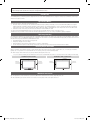
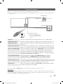
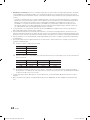
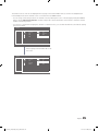
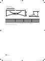
Ensuring Proper Ventilation
When you install the TV, maintain the distances shown below between the TV and other objects (walls, cabintet sides, etc.) to ensure proper ventilation.
Failing to do so may result in a fire or problems with the TV caused by an increase in its internal temperature.
✎✎ When using a stand or wall-mount, use parts provided by Samsung Electronics only.
xx If you use parts provided by another manufacturer, it may cause a problem with the product or cause the product to fall, leading to serioius injury.
Installation with a stand.
Installation with a wall-mount.
4 inches
4 inches
4 inches
4 inches
4 inches
4 inches
4 inches
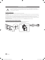
Additional Information
✎✎ The appearance of the TV and its accessories may differ from the illustrations in this manual, depending on the TV.
✎✎ Be careful when you touch the TV if it is on or has been on for a period of time. Some parts can be hot.
[HC890V_ZA]Install_Guide_00ENG.indd 2
2014-07-10
3:31:41
Contents
Introduction............................................................................................................................................................... 2
Operational Modes.................................................................................................................................................... 2
Still image warning..................................................................................................................................................... 2
Ensuring Proper Ventilation ....................................................................................................................................... 2
Additional Information................................................................................................................................................ 2
Accessories............................................................................................................................................................... 4
Installing the LED TV Stand........................................................................................................................................ 5
Using the TV's Controller........................................................................................................................................... 7
The Connection Panel................................................................................................................................................ 8
The Remote Control................................................................................................................................................. 10
Using the Samsung Smart Control........................................................................................................................... 12
Connecting to the Network...................................................................................................................................... 17
Connecting the TV to an SBB or STB...................................................................................................................... 19
Connecting the Bathroom Speakers........................................................................................................................ 22
Connecting the RJP (Remote Jack Pack)................................................................................................................. 23
Setting the Hotel Option Data.................................................................................................................................. 25
Installing the Wall Mount.......................................................................................................................................... 46
Securing the TV to the Wall...................................................................................................................................... 48
Specifications.......................................................................................................................................................... 49
Display Resolution................................................................................................................................................... 50
Dimensions.............................................................................................................................................................. 51
ENGLISH
yy
yy
yy
yy
yy
yy
yy
yy
yy
yy
yy
yy
yy
yy
yy
yy
yy
yy
yy
yy
yy
Symbols Used in this Manual
t
TOOLS
Indicates that you can press the
TOOLS button on the remote control
to use this function.
Note
One-Touch Button
English
[HC890V_ZA]Install_Guide_00ENG.indd 3
3
2014-07-10
3:31:41
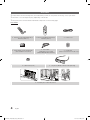
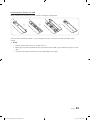
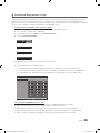
Accessories
✎✎Please make sure the following items are included with your LED TV. If any items are missing, contact your dealer.
✎✎The items’ color and shape may vary, depending on the model.
✎✎The parts for the stand are listed under Stand Components on the following page.
List of Parts
MIC
TV
SEARCH
VOL
RETURN
EXIT
KEYPAD
VOICE
SMART HUB
SOURCE
CH
GUIDE
CH.LIST
yy Remote Control (AA59-00817A) &
Batteries (AAA x 2)
yy Smart Control(BN59-01181N) &
Batteries (AA x 2)
yy Safety Guide / Quick Setup Guide
(Not available in all locations)
yy Data Cable
(depending on the model)
(BN39-00865B, BN39-01011C)
yy Cable Holder (1 EA)
yy Power Cord
yy Holder Ring
(4EA, in more than 65" models only)
yy 3D glasses (BN96-31824A, Sold separately)
yy Assembling the Holder Wire Stand
4
English
[HC890V_ZA]Install_Guide_00ENG.indd 4
2014-07-10
3:31:42
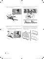
Installing the LED TV Stand
A
B
C
Stand
Guide Stand
x8 (M4 X L12)
Screws
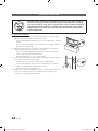
[[Warning
Do not remove the packing material on the front of TV screen.
1 Locate the Base, Stand Mount, and Screws in the box
and set them aside.
2 With another person, hold the TV by its edges, and then
remove it completely from the box.
✎✎Remove the top portion of the box to locate the
stand parts.
x8
3 Lay the TV on a soft surface, screen side down. Use the
Styrofoam to protect the screen.
4 Fit the Base and Stand Mount together, making sure the
notch on the Stand Mount aligns with the Base.
English
[HC890V_ZA]Install_Guide_00ENG.indd 5
5
2014-07-10
3:31:44
5 Insert 4 screws, and then use a screwdriver to secure
the Base to the Stand Mount.
6 Holding the stand parallel to the screen, slide the Stand
Mount into the notches on the back of the TV.
6-1
6-2
6-3
x4 (M4 X L12)
7 Insert 4 screws, and then use a screwdriver to secure
the stand to the TV.
✎✎To assemble the wall mount, use the styrofoam that
came with the TV’s packaging to protect it. Lay the
TV down and attach the screws.
8 After attaching the stand, set the TV upright, and then
remove the Styrofoam from the front of the TV. Do not
place the TV at the edge of any piece of furniture (table,
entertainment center, etc.). It could fall and break or
cause personal injury.
x4 (M4 X L12)
6
English
[HC890V_ZA]Install_Guide_00ENG.indd 6
2014-07-10
3:31:46
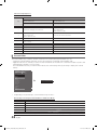
Using the TV's Controller
✎✎The color and shape of the TV Controller may vary depending on the model.
✎✎The TV's Controller, a small joy stick like button on the bottom right side of the TV, lets you control the TV without the
remote control.
Open Smart Hub.
Open the menu.
m
R
Select a source.
P
Turn off the TV.
TV Controller
The control stick is located on the lowerleft corner of the back of the TV
Remote control sensor
When you use the Samsung Smart
Control, the standby LED does not
respond, except when you press the
P button.
Power on
Turn the TV on by pressing the Controller when the TV is in standby mode.
Adjusting the volume
Adjust the volume by moving the Controller from side to side when the power is on.
Selecting a channel
Select a channel by moving the Controller backwards and forwards when the
power is on.
Using the Function menu
To view and use the Function menu, press and release the Controller when the
power is on. To close the Function menu, press and release the Controller again.
Selecting the MENU (m)
With the Function menu visible, select the MENU (m) by moving the Controller
to the left. The OSD (On Screen Display) Menu appears. Select an option by
moving the Controller to the right. Move the Controller to the right or left, or
backwards and forwards to make additional selections. To change a parameter,
select the it, and then press the Controller.
Selecting SMART HUB (™) With the Function menu visible, select SMART HUB (™) by moving the
Controller upwards. The SMART HUB main screen appears. Select an
application by moving the Controller, and then pressing the Controller.
Selecting a Source (s)
With the Function menu visible, open the Source screen (s) by pushing the Controller
to the right. The Source screen appears. To select a source, move the Controller back
and forth. When the source you want is highlighted, press the Controller.
Power Off (P)
With the Function menu visible, select Power Off (P) by pulling the Controller
forwards, and then press the Controller.
✎✎To close the Menu, SMART HUB, or Source, press the Controller for more than 1 second.
Standby mode
Your TV enters Standby mode when you turn it off, and continues to consume a small amount of electric power. To be safe
and to decrease power consumption, do not leave your TV in standby mode for long periods of time (when you are away on
vacation, for example). It is best to unplug the power cord.
English
[HC890V_ZA]Install_Guide_00ENG.indd 7
7
2014-07-10
3:31:47
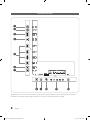
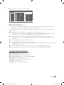
The Connection Panel
1
2
3
4
5
6
7
8 9 0
!
@
✎✎Whenever you connect an external device to your TV, make sure that power on the TV and the device is turned off.
✎✎When connecting an external device, match the color of the connection terminal to the cable.
8
English
[HC890V_ZA]Install_Guide_00ENG.indd 8
2014-07-10
3:31:47
1 V
ARIABLE AUDIO OUT: Used for the audio output to the Bathroom speaker. Connect the Bathroom Wall Box and the Variable port.
2 V
OL-CTRL: Used to control the volume of the Bathroom speaker. Connect the Bathroom Wall Box and the VOLCTRL port.
3 U
SB (HDD/1.0A) / CLONING
–– Connector for software upgrades and Media Play, etc.
–– Service connection.
4 D
IGITAL AUDIO OUT (OPTICAL): Connects to a Digital Audio component.
5 H
DMI IN 1(DVI), 2(ARC), 3, 4: Connects to the HDMI jack of a device with an HDMI output.
✎✎ No separate sound connection is needed for an HDMI to HDMI connection. HDMI connections carry both audio
and video.
✎✎ Use the HDMI IN 1(DVI) jack for a DVI connection to an external device. Use a DVI to HDMI cable or DVI-HDMI
adapter (DVI to HDMI) for the video connection and the PC/DVI AUDIO IN jacks for audio. Some DVI or HDMI
devices may not or should not need a DVI AUDIO IN connection for audio.
✎✎ It is recommended that the external device of the HDMI 1.3 or 1.4 version will be used with this TV. If you meet the
compatible problem like no sound or the abnormal screen or etc with the device of the HDMI 1.2 version, contact
to the Samsung customer care center. Refer to page 54 for the information of the Samsung customer care center.
6 DVI AUDIO IN: Connects to the audio out jack of an external DVI device using a 1/8th inch stereo phone jack cable.
Some DVI devices may not or should not need this connection audio.
7 AUDIO OUT: Connects to the audio input jacks on an Amplifier/Home Theater.
8 E
X-LINK: Connect this jack to the jack on the optional RJP (Remote Jack Pack). This will allow you to connect external
devices (Camcoder, PC, DVD players etc.) easily.
9 DATA
–– Used to support data communication between the TV and the SBB or STB.
–– Connects using RJ-12 TV type plugs.
0 ANT IN (AIR/CABLE)
–– To view television channels correctly, the TV must receive a signal from one of the following sources:
–– An outdoor antenna / A cable television system / A satellite receiver
! COMPONENT IN / AV IN 1
–– Use to connect to Component video / audio devices such as DVD players and AV (Composite) devices such as VCRs.
–– Connect audio cables to "R-AUDIO-L" on your TV and the other ends to corresponding audio out jacks on A/V or
Component devices.
–– The COMPONENT IN jack is also used as the VIDEO jack.
–– Connect component video cables (not supplied) to the component jacks ("PR", "PB", "Y") on the rear of your TV and the
other ends to corresponding component video out jacks on a DVD player. Match the colors on the jacks and cables.
–– If you want to connect both a Set-Top Box and a DVD player, you should connect the Set-Top Box to the DVD and
connect the DVD to the component jacks ("PR", "PB", "Y") on your TV.
–– The PR, PB and Y jacks on your component devices (DVD) are sometimes labeled Y, B-Y and R-Y or Y, Cb and Cr.
–– For AV devices, connect RCA audio cables (not supplied) to "R - AUDIO - L" on the rear of the TV set and the other
ends to corresponding audio out jacks on an external device.
–– When your are connecting a composite (AV) device to AV IN1 [Y/Video], connect the video cable (Yellow) to the
AV IN1 [Y/VIDEO] jack (Green/Yellow) .
@ L
AN: Connect to a wired LAN using CAT 7 cable.
English
[HC890V_ZA]Install_Guide_00ENG.indd 9
9
2014-07-10
3:31:47
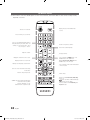
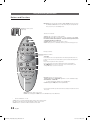
The Remote Control
✎✎This remote control has Braille points on the Power, Channel, and Volume buttons and can be used by visually
impaired customers.
Display and select the available video
sources.
Turns the TV on and off.
Press to directly access channels.
Press to select additional digital channels
being broadcast by the same station. For
example, to select channel ‘54-3’, press
‘54’, then press '-' and ‘3’.
Adjust the volume.
Return to the previous channel.
Cut off the sound temporarily.
VOL
CH
Display the channel list on the screen.
HOME
Display the main on-screen menu.
CONTENT
Quickly select frequently used functions.
Change channels.
Press to display the HOME menu or the
REACH menu or the SINC menu
Displays My Contents, Watch TV and
Source icons on the TV screen.
Press to display channel and TV information
on the TV screen.
Select on-screen menu items and change
menu values.
Return to the previous menu.
Exit the menu.
ALARM
SLEEP: Set when TV will automatically be
turned off for the sleep timer.
X: Turns the 3D image on or off.
CC: Controls the caption decoder.
10
SLEEP
CC
Buttons used in Channel list, Media Play
menu, etc.
button: Set when TV will automatically
is turned on for the alarm
Use these buttons in the Media Play and
Anynet+ modes.
English
[HC890V_ZA]Install_Guide_00ENG.indd 10
2014-07-10
3:31:48
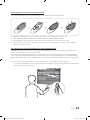
Installing batteries (Battery size: AAA)
Match the polarity of the batteries to the symbols in the battery compartment.
X
Y
Z
After you have installed the batteries, use a screwdriver to screw in the screw that holds the battery cover
closed.
✎✎ NOTE
•• Use the remote control within 23~33 feet of the TV.
•• Bright light may affect the performance of the remote control. Avoid using near fluorescent lights or neon
signs.
•• The color and shape of the remote may vary depending on the model.
English
[HC890V_ZA]Install_Guide_00ENG.indd 11
11
2014-07-10
3:31:48
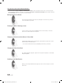
Using the Samsung Smart Control
Buttons and Functions
MIC
Microphone: Use the microphone with the Voice Control and Voice functions.
‐‐ The Voice Control function can be affected by unclear pronunciation, voice level, or surrounding noise.
TV
KEYPAD
SEARCH
MUTE: Cuts off the sound
temporarily.
SOURCE
VOICE
P
SEARCH: Run search function. ( Not available )
KEYPAD: Displays the On-Screen Remote. See the e-Manual chapter, Using
the Remote Control and Peripherals > Using the Samsung Smart Control
> Displaying the On-Screen Remote.
SOURCE: Displays and lets you select video sources.
VOICE: Takes your voice commands and lets you enter text using your voice.
MIC
TV
SEARCH
RETURN
KEYPAD
SOURCE
EXIT
VOL
Turns the TV on and off.
SMART HUB
GUIDE
CH.LIST
CH
VOICE
REC
TTX
MENU
Changes channels.
Adjusts the volume.
M.SCREEN
RETURN
EXIT
SMART HUB
3D
SLEEP
MENU
CC
HOME
GUIDE
CH.LIST
Touch pad
Place a finger on the touch pad and move the Samsung Smart Control. The
pointer on the screen moves in the direction you moved the Samsung Smart
Control.
Press the touch pad to run the focused item.
Press and hold the touch pad to display the Context-Sensitive Menus.
< > ¡ £: Moves the cursor, selects the on-screen menu items, and
changes the values seen on the TV's menu.
ALARM
RETURN: Returns to the previous menu.
SMART HUB: Brings up Smart Hub applications. See the e-Manual chapter,
Smart Features > Smart Hub.
‐‐ To exit an application quickly, press the ™ button.
GUIDE: Displays the EPG (Electronic Program Guide).
Use these buttons with a specific feature and according to the directions on the
TV's screen.
MENU: Displays the menu on the screen.
HOME: Press to display the HOME menu or the REACH menu or the SINC menu.
3D: Turns the 3D function on or off.
SLEEP: Press to set when TV will be turned off after a preset period of time.
CC: Controls the caption decoder and displays captions on the screen.
ALARM: Press to set when TV will be turned on for the alarm.
12
English
[HC890V_ZA]Install_Guide_00ENG.indd 12
2014-07-10
3:31:49
Installing Batteries into the Samsung Smart Control
To use the Samsung Smart Control, insert the batteries into the device referring to the figure below.
1. Gently pull on the battery cover's notch and then remove the cover completely once it comes loose.
2. Insert 2 AA alkaline batteries, making sure to align the positive and negative polarities correctly.
3. Place the battery cover on the remote control and insert the top part of the cover into the remote control.
4. Press the catches on both sides of the battery cover in the order shown by the figure so that the cover is completely
attached to the remote control.
Using the Samsung Smart Control Motion Function to Operate the TV
The Samsung Smart Control has a motion sensor (gyro sensor) that lets you control the TV easily by moving the Samsung
Smart Control and using it much like a cordless mouse.
Place a finger on the Samsung Smart Control's touch pad, and then move the Samsung Smart Control. A pointer appears
on the screen. Move the Samsung Smart Control, and pointer moves on the screen in the direction you moved the Samsung
Smart Control and the same distance. Highlight an item on the screen with the pointer, and then press the touch pad to select
it.
You can also move the Samsung Smart Control in the same fashion to scroll scrollable screens up and down.
–– If you stop using the Motion Function, even momentarily, put your finger on the touch pad, and then move the Samsung
Smart Control to re-start the function.
English
[HC890V_ZA]Install_Guide_00ENG.indd 13
13
2014-07-10
3:31:50
Using the Touch Pad and the Directional Buttons
–– In the TV's menu, navigate to Support > Smart Control Tutorial to view a tutorial that shows how to use the touch pad.
–– If the touch pad's sensitivity is too high or low, navigate to the System > Smart Control Settings menu, and then select the
Touch Sensitivity option to change the touch pad sensitivity.
Moving the Focus or Pointer
Press the directional buttons (up, down, left, and right) to move the focus, pointer, or
cursor in the direction you want.
Entering the Menu / Selecting an Item
To enter a menu or select an item, highlight the item or the menu title, or move the
pointer over it, and then press the touch pad.
Displaying a Context-sensitive Menus in Smart Hub
In Smart Hub, highlight an item, and then press and hold the touch pad. The contextsensitive menu for the item pops up.
–– The context-sensitive menu may vary depending on the item you selected.
Changing the Smart Hub Panel
On a Smart Hub panel, drag left or right on the touch pad. The previous or next Smart
Hub panel appears.
Scrolling on the Web Browser
When you are using the web browser, drag up or down on the touch pad to scroll the
web screen.
14
English
[HC890V_ZA]Install_Guide_00ENG.indd 14
2014-07-10
3:31:51
Reconnecting the Samsung Smart Control to the TV
If the Samsung Smart Control stops operating or works abnormally, try replacing the batteries. If the problem persists, pair the
Samsung Smart Control and TV again.
1. Move to within a foot of the TV, and then aim the Samsung Smart Control at the TV's remote control receiver.
Remote Control Sensor
2. Press the RETURN button and GUIDE button simultaneously for 3 seconds.
3. The connection icon appears on the screen. A few moments later, the connected icon appears. The Samsung Smart
Control is paired to the TV.
The Low Battery Alarm Window
If the Samsung Smart Control's batteries become low, the Low Battery Alarm appears on the screen. When the Alarm
appears, replace the batteries. We recommend using alkaline batteries for longer operating life.
<Low battery Alarm Icon>
English
[HC890V_ZA]Install_Guide_00ENG.indd 15
15
2014-07-10
3:31:52
Displaying and Using the On-Screen Remote
Press the KEYPAD button on the Samsung Smart Control to display the On-Screen Remote on the TV's screen. Use the
On-Screen Remote to enter numbers, control content playback, and use the features and functions of the TV, just like a real
remote. Use the directional buttons on the Samsung Smart Control to move the cursor on the On-Screen Remote. Press the
touch pad on the Samsung Smart Control to select.
–– The On-Screen Remote buttons may vary depending on the TV features or functions you are using.
Button
Description
Lets you switch channels by entering channel numbers directly. Select Pre-CH to return to the
previous channel.
Controls the playback of video, photo, or music files from all sources, and the playback of
media content on external devices (for example, a Blu-ray player).
a, b, {, }
Use these colored buttons to access additional options specific to the feature in use.
TOOLS
Press to display the Tools menu while you are watching TV. The Tools menu gives you easy
access to frequently used functions. The functions listed are context-sensitive and vary
depending on how you are currently using the TV.
INFO
Shows information about the current digital broadcast program or content.
MENU
Displays the TV's menu on the screen.
3D
Lets the 3D source displayed.
PIP
Lets you display video from an external device or computer on the main screen and a TV
broadcast in a picture-in-picture window.
CC
Select to turn subtitles on or off.
P.Size
Changes the picture size.
SLEEP
This function automatically shuts off the TV after a preset period of time.
P.Mode
Lets you select the Picture Mode.
Web Browser
Launches the Web Browser.
ALARM
Set the alarm time when TV will automatically be turned on.
Move To The Right / Move To The Left: Moves the Onscreen Remote on the screen.
Large Size / Normal Size: Resizes the Onscreen Remote on the screen. Alternatively, navigate
to the System > Smart Control Settings menu and select and set the Onscreen Remote
Size option.
Touch Sensitivity: Lets you change the touch pad sensitivity.
Alternatively, navigate to the System > Smart Control Settings menu and select and set the
Touch Sensitivity option.
Cancel: Select to close a pop up menu.
16
English
[HC890V_ZA]Install_Guide_00ENG.indd 16
2014-07-10
3:31:52
Connecting to the Network
You can set up your TV so that it can access the SMART TV applications through your local area network (LAN) using a wired
or wireless connection.
✎✎After you have “physically” connected your TV to your network, you must configure the network connection to complete
the process. You can configure the connection after the Initial Setup process, through the TV’s menu.
Network Connection - Wireless
Connect the TV to the Internet using a standard wireless router or modem.
Wireless IP Router or Modem
that has a DHCP Server
The LAN Port on the Wall
LAN Cable (Not Supplied)
Network Connection - Wireless
yy This Smart TV supports the IEEE 802.11a/b/g /n communication protocols. Samsung recommends using IEEE 802.11n.
Otherwise, when you play video over a network connection, the video may not play smoothly.
yy To use a wireless network, the TV must be connected to a wireless router or modem. If the wireless router supports DHCP,
the TV can use a DHCP or static IP address to connect to the wireless network.
yy Select a channel that is not currently in use for the wireless router. If the channel set for the wireless router is currently
being used by another device, the result is usually interference and/or a communications failure.
yy Most wireless networks have an optional security system. To enable a wireless network's security system, you need to
create a security key using characters and numbers, and then enter that key into the router through its menu. You then
must enter this security key into any other devices you want to connect to the wireless network.
Network Security Protocols
The TV only supports the following wireless network security protocols:
yy Authentication Modes: WEP, WPAPSK, WPA2PSK
yy Encryption Types: WEP, TKIP, AES
In compliance with the newest Wi-Fi certification specifications, Samsung TVs do not support WEP or TKIP security encryption
in networks running in the 802.11n mode.
If the wireless router supports WPS (Wi-Fi Protected Setup), you can connect the TV to your network using PBC (Push Button
Configuration) or a PIN (Personal Identification Number). WPS automatically configures the SSID and WPA key settings.
Your Smart TV cannot connect to uncertified wireless routers.
English
[HC890V_ZA]Install_Guide_00ENG.indd 17
17
2014-07-10
3:31:53
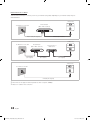
Network Connection - Wired
There are three main ways to connect your TV to your network using cable, depending on your network setup. They are
illustrated below:
TV Rear Panel
External Modem
(ADSL / VDSL / Cable TV)
The Modem Port on the Wall
Modem Cable (Not Supplied)
LAN Cable (Not Supplied)
TV Rear Panel
The Modem Port on the Wall
External Modem
(ADSL / VDSL / Cable TV)
Modem Cable
(Not Supplied)
IP Router that has a
DHCP Server
LAN Cable
(Not Supplied)
LAN Cable
(Not Supplied)
TV Rear Panel
The LAN Port on the Wall
LAN Cable (Not Supplied)
✎✎The TV does not support network speeds less than or equal to 10Mbps.
✎✎Use Cat 7 cable for the connection.
18
English
[HC890V_ZA]Install_Guide_00ENG.indd 18
2014-07-10
3:31:53
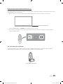
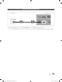
Connecting the TV to an SBB or STB
Data Cable
TV Rear Panel
ETH MODEM
1.Connect the DATA jack of the TV to the ETH MODEM jack of the STB (SBB) with the Data cable.
✎✎ The "ETH MODEM" jack name that you connect the Data Cable to may differ depending on the SBB or STB type.
English
[HC890V_ZA]Install_Guide_00ENG.indd 19
19
2014-07-10
3:31:53
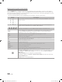
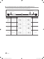
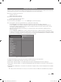
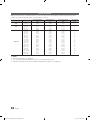
¦¦ List of Hospitality SI Vendors and Compatible Data Cables Supplied with the TV
yy Confirm you are using the correct data cable for your SI vendor. Refer to the code label on the data cables.
yy Contact your nearest dealer or your SI Vendor to buy the data cable not included in the TV.
Confirm the code on the
Code Label
Note the labeled end.
Note the labeled end.
20
SI Vendor
Cable code
Samsung
OCC
Enseo
Guest-Tek
BN39-00865B
NXTV
BN39-01011B
nStreams
BN39-01110A
Sonifi
BN39-01011E
Pin assign
Remark
Provided
Provided
English
[HC890V_ZA]Install_Guide_00ENG.indd 20
2014-07-10
3:31:54
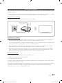
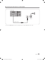
¦¦ Connecting the Audio Output to an Audio Amplifier
TV Rear Panel
AUDIO IN
Audio
Amplifier
1 Stereo cable
1.Connect the AUDIO OUT port of the TV to the Audio In port of an audio amplifier with a stereo cable.
English
[HC890V_ZA]Install_Guide_00ENG.indd 21
21
2014-07-10
3:31:54
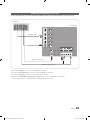
Connecting the Bathroom Speakers
You can connect the Bathroom Speakers in the following manner.
¦¦ Connecting through the Variable Output (available without an external amplifier)
TV Rear Panel
1
Speaker
2
Volume Control Box
VOL+
VOL-
1.Connect the VARIABLE AUDIO OUT port of the TV to the Bathroom Wall Speakers of the hotel.
Speaker +
Speaker -
N/C
✎✎ The VARIABLE AUDIO OUT port supports MONO sound out only.
✎✎ Speaker Wire: Use speaker cable no more than 82 feet (25m) in length.
✎✎ The maximum speaker output is 4W, 8Ω.
2.Connect the VOL-CTRL jack of the TV to the Volume Control Box Switch port on the Bathroom Wall of the hotel.
Volume Control Box
VOL +
1
3
2
VOL -
VOL - UP
GND
VOL - DOWN
( White 1 ) ( Black /Red 2 ) ( Shield Wire 3 )
yy Installing the Volume Control
–– If you configure the Volume Control Box as shown in the figure above, you can control the volume of the bathroom
speakers.
–– The jack that connects the Volume Control Box to the TV is a 3.5mm normal Phone jack.
–– Volume Control Box switch is a Tact switch.
3.Set the Sub AMP Mode
–– 0: Deactivates the sub amplifier that outputs the voice signal of VARIABLE AUDIO OUT. No voice signal is output from
VARIABLE AUDIO OUT.
–– 1: Adjusts the voice output of VARIABLE AUDIO OUT according to the volume level of the TV speaker. And all settings
for the Hotel mode menus of Power On Volume Num, Min Volume, and Max Volume apply to the TV, speakers, and
VARIABLE AUDIO OUT.
–– 2: Determines the volume according to the bathroom control panel setting.
22
English
[HC890V_ZA]Install_Guide_00ENG.indd 22
2014-07-10
3:31:54
Connecting the RJP (Remote Jack Pack)
Connect the input jacks on the TV to the RJP. The RJP lets guests connect audio and video sources to the TV.
RJP Rear
USB
HDMI
S-VIDEO RCA
AUDIO/PC
RS/232
TV Rear Panel
1 HDMI cable
2 DVI Audio cable
3 RS-232 Data Cable
4 Video / Audio Cable
1.Connect the [HDMI] port of the TV to the HDMI port of the RJP.
2.Connect the DVI AUDIO IN port of the TV to the PC/AUDIO port of the RJP.
3.Connect the EX-LINK port of the TV to the RS/232 port of the RJP.
4.Connect the COMPONENT IN [VIDEO] / [R-AUDIO-L] port of the TV to the RCA port of the RJP.
✎✎This Samsung TV is compatible with the TeleAdapt TA-7610 RJP only.
English
[HC890V_ZA]Install_Guide_00ENG.indd 23
23
2014-07-10
3:31:55
yy RJP (Remote Jack Pack): The RJP is a hardware module that has various Audio and Video inputs (A/V Video, A/V Audio,
PC and HDMI) and corresponding outputs. The corresponding outputs are connected from the RJP to the TV. The RJP
communicates with the TV via RS232. The RJP communicates with the TV by sending messages regarding Active/Inactive
sources.
–– A group of hotel menu items let you assign numbered priorities to the jacks of the RJP. (See page 26). 1 is the highest
priority and 3 is the lowest. When a guest connects external sources to the RJP jacks, the TV will automatically switch
between sources based on the priority you have assigned them in the Menu. For example, lets say AV is set to 1
and HDMI to 2. If a guest has attached a device to the HDMI jack, and then plugs a device into the AV jack, the TV
automatically switches to the device plugged into the AV jack (the jack with the higher priority). Note that a guest can
also switch between devices manually by pushing a button on the RJP.
yy To reset the RJP to its factory default state, press the AV and HDMI buttons simultaneously for 10 seconds. When all
button LEDs blink 5 times, the RJP reset is complete.
yy The RJP will automatically turn off any LEDs after 5 minutes to avoid unnecessary light pollution in the hotel room. The
LEDs that were turned off will turn on again if the guest touches any of the buttons and the 5 minute timer will restart. If the
guest then touches another source button, the TV will change to the selected source and the corresponding LED will be lit.
yy After an RJP Reset or a TV Power OFF/ON, it takes approximately 10 seconds to establish communications between the
TV and the RJP.
yy The following table shows the approximate time in seconds it takes to switch from the TV to an input source, based on
assigned or default priorities.
✎✎ Scenario 1 : When no inputs are connected.
Source
To Connect
AV
PC
HDMI
2 Sec
0.7 Sec
3.9 Sec
✎✎ Scenario 2: When two or more inputs are connected to the RJP and one of the input sources is disconnected and
then reconnected.
Source
Disconnect
To Connect
Total
AV
PC
HDMI
4.5 Sec
0.7 Sec
3.9 Sec
2 Sec
0.7 Sec
3.9 Sec
6.5 Sec
1.4 Sec
7.8 Sec
✎✎ An example: If the RJP has all its live sources (AV, PC, and HDMI) connected, AV has been assigned the highest
priority, the RJP is in HDMI mode, and a guest removes and reconnects the AV source, the minimum time required
to switch to the AV source is 6.5 seconds.
yy To play audio devices (Ipods, MP3 devices, etc.) through the RJP, you must turn Music Mode AV in the menu on. (See
page 26)
yy Music mode in the TA-7610 RJP is supported by the AV jack only. HDMI Music mode is available for the Guestlink RJP
only.
24
English
[HC890V_ZA]Install_Guide_00ENG.indd 24
2014-07-10
3:31:55
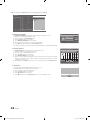
Setting the Hotel Option Data
To let you control how the TV functions when in Hotel mode, the TV has two Hotel mode menus, the Stand-alone mode menu
and the Interactive mode menu. The menu items that differ between the modes are listed below.
Menu items in the Stand-alone mode only:
–– SI Vendor : Smoovie
–– REACH Server and its submenus.
Menu items in the Interactive mode only:
–– SI Vendor: Samsung and other vendors.
All other items appear in both modes.
To access the menus, press MUTE → 1 → 1 → 9 → ENTERE on your Samsung remote.
After a menu appears, follow these general directions to navigate and change values:
–– Use the Up and Down arrow buttons on the Samsung remote to move from menu item to menu item.
–– Press the ENTER or Left or Right arrow buttons to select a menu item. The screen displays that menu item only.
–– Press the Left or Right arrow button to change a value. The Right arrow button increases numerical values. The Left
arrow button decreases numerical values.
–– When the screen is displaying one menu item, you can press the Up or Down arrow button to display the next or
previous menu item.
–– Press the RETURN or MENU button to exit the current menu item and go to a higher menu level or the Main menu.
–– To exit a Hotel mode menu, turn off the TV, and then turn it on again. Any changes you made are saved except changes
to SI Vendor. For changes to SI Vendor, you must turn the TV off, wait until the Standby light glows steadily, then unplug
the TV, wait for the Standby LED to go off, and then plug the TV in again.
Hospitality Mode
Standalone
SI Vendor
OFF
Power On
Widget Soulution
DRM
Service
Channel
Menu OSD
Clock
Music Mode
Remote Jack Pack
External Source
Bathroom Speaker
Eco Solution
Logo/Message
Cloning
REACH Solution
Network
Above: The Hotel mode menu
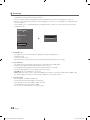
To change menus between the interactive mode and the standalone mode, follow the steps below :
1.Highlight the Hospitality Mode menu item in the top left corner of the menu.
2.Press the left or right arrow button on the Samsung remote. Only the Hospitality Mode menu item is displayed.
3.Press the left or right arrow button to change the Hospitality Mode item from Standalone to Interactive or from Interactive to
Standalone.
4.Press the Return or Menu button on the remote. The entire menu re-appears with your selection displayed in the Hospitality
Mode field.
✎✎ After you have set the values in one TV, you can clone those values to multiple TVs. See USB Cloning on page 32.
English
[HC890V_ZA]Install_Guide_00ENG.indd 25
25
2014-07-10
3:31:55
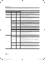
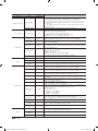
¦¦ Menu Items
To Enter this menu: Press the MUTE → 1 → 1 → 9 → ENTER buttons in order.
To exit from this menu : Power Off (or Power Off and unplug if you have changed SI Vendor), and then turn on again. Any
changes you made are saved.
Hotel TV Function
Category
Item
initial value
Hospitality Mode
Hospitality Mode
Standalone
SI Vendor
SI Vendor
OFF
Select Hospitality mode.
• Interactive mode : TV works with an SI STB or SBB.
• Standalone mode : TV works alone, without an SI STB or SBB.
• Interactive mode : Samsung / OCC / MTI / Nstreams / NXTV / Enseo / Cardinal / Guestek / Seachange / EBL
• Standalone mode : OFF / Smoovie
Set the default values that will be applied when the TV is turned.
• User Defined : Lets you set Power On Channel and Channel Type manually.
See Power On Channel and Channel Type below.
• Last Saved : If you select this item, when the TV is turned on, it displays the
channel it was displaying when it was turned off.
Power On Channel
Last Saved
Power On Channel
Num
…
When the TV is turned on, it switches automatically to this channel.
Power On Channel
Type
…
• Select channel band : AIR (analog air band), DTV (digital air band), CATV
(analog cable band), CDTV (digital cable band).
Power On Volume
Last Saved
Power On Volume
Num
…
The TV turns on with this Volume Level in Stand Alone Hospitality mode.
The minimum Volume Level the user can set in Stand Alone Hospitality mode.
Power On
• User Defined : Lets you set the Power On Volume manually. See Power On
Volume below.
• Last Saved : When the TV is turned on, it returns to the volume that had been
set when the power had been turned off.
Min Volume
0
Max Volume
100
The maximum Volume Level the user in Stand Alone Hospitality mode.
Power On Source
TV
Select the input source the TV displays when turns on.
Determines the TV's state when power returns after a power failure or after you
have unplugged the TV and then plugged it in again.
• LAST OPT : Returns to its last Power state. If it was in Stand-by, it returns to
Standby. If it was on, it turns on.
• Power On : When the power returns, the TV turns on.
• Standby : When the power returns, the TV enters the Standby mode.
Power On Option
Last Option
Channel Setup
…
Gives you direct, immediate access to some of the Channel menu functions on
the user Channel menu such as Auto Program, Antenna selection, etc.
…
The Channel Editor lets you edit the channels stored in the TV's memory. Using
Channel Editor you can:
• Change the channel numbers and names, and sort the channels in your
desired channel number order.
• Apply the video mute to channels you select. The video mute blanks out
the video from a channel and outputs only the sound while displaying a
speaker icon on the screen.
The Channel Editor also lets you view information about each channel easily,
without your having to display each channel directly.
Channel Editor
Channel
26
Description
Channel Bank
Editor
If you set Hospitality Mode to Standalone and SI Vendor to Smoovie, this item is
displayed. Lets you edit the channel bank that works with the Smoovie Remote.
Refer to page 40.
Dynamic SI
• On : Check the DTV Program channel number. (If Dynamic SI is On, it is
not availale to edit DTV channels in Channel Editor.)
• Off : Does not check the DTV Program channel number. (If Dynamic SI
is Off, it is available to edit DTV channels in Channel Editor,but additional
DTV channel program number update is not supported.)
OFF
English
[HC890V_ZA]Install_Guide_00ENG.indd 26
2014-07-10
3:31:55
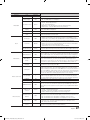
Hotel TV Function
Category
initial value
Picture Menu Lock
OFF
Enable or disable the Picture Menu.
ON
• On : The Main Menu is displayed.
• Off : The Main Menu is not displayed.
Menu Display
Unlock
Home Menu
Display
ON
OFF:The Home Menu is not displayed.
ON:The Home Menu is displayed.
Home Menu Editor
…
Edit Home Menu .
Home Menu Auto
Start
…
ON:The Home Menu is Auto Start.
OFF:The Home Menu is not Auto Start.
Clock Type
OFF
• OFF : The feature of SW Clock becomes not available.
• SW Clock : If this item is selected and a user presses the INFO key of the
remote twice consecutively in the standby mode of TV, the clok information is
displayed in the screen of TV and then TV is turned off automatically.
Local Time
Manual
Select the way to update the clock data
• Manual : The clock is set automatically from the DTV channel or manually by
the user when the TV is in stand-alone mode.
• Time Channel : The clock is set from the selected channel.
Time Channel Type
CDTV
Select channel band of the channel to get the time information : AIR (analog air
band), DTV (digital air band), CATV (analog cable band), CDTV (digital cable band).
Time Channel Num
1
Music Mode AV
OFF
Allows music output from an mp3/audio player connected to an AV Input Source
on the TV. When on, you can hear sound from the player through the TV whether
there is a video signal or not. Also mutes the video so the TV does not display a
picture when a guest is playing music. The TV's backlight, however, remains on.
Music Mode
Comp
OFF
Allows music output from an mp3/audio player connected to an Component Input
Source on the TV. When on, you can hear sound from the player through the TV
whether there is a video signal or not. Also mutes the video so the TV does not display
a picture when a guest is playing music. The TV's backlight, however, remains on.
Music Mode
Backlight
OFF
When set to Off, the TV's backlight is turned off entirely when a guest uses the
Music mode. To save energy, set to Off.
Clock
Music Mode
External Source
Turning the front panel (local key) operations on/off.
• Unlock : Unlocks all panel keys.
• Lock : Locks all panel keys.
• OnlyPower : Locks all panel keys except the Power panel key.
• Menu/Source : Locks the Menu and Source panel keys.
Panel Button Lock
Menu OSD
Remote Jack Pack
Description
Item
Select the number of the channel to get the time information.
Priority AV
1
Lets you set the priority of the 7610 RJP AV jack. You can choose 1, 2, or 3, with 1 being
the highest and 3 the lowest. The TV automatically displays the source with the higher
priority. For example, lets say AV is set to 1 and HDMI is set to 2. If a guest has attached a
device to the HDMI jack, and then plugs a device into the AV jack, the TV will automatically
switch to the device plugged into the AV jack (the jack with the higher priority). Note that a
guest can also switch devices manually by pushing a button on the 7610 RJP.
Priority HDMI
2
Lets you set the priority of the 7610 RJP HDMI jack. You can choose 1, 2, or
3, with 1 being the highest and 3 the lowest. The TV automatically displays
the source with the higher priority. See above for a more detailed explanation.
Select which AV source of the TV is connected to the RJP jack.
AV Option
AV
HDMI Option
HDMI 1
Select which HDMI source of the TV is connected to the RJP jack. (HDMI1/HDMI2/HDMI3)
HDMI Music Mode
OFF
Allows music output from an mp3/audio player connected to an HDMI Input Source.
When on, you can hear sound from the player through an HDMI input of the RJP
whether there is a video signal or not. (This option is only compatible with the Guest
link RJP.)
USB Pop-up
Screen
Default
External Source
Banner
ON
If set to On, the TV displays the External Source Banner (information) when you
change the TV source to another external input, press the Info key, or turn the TV on.
• On : The External Source information is displayed on the TV screen.
• Off : The External Source information is not displayed on the TV screen.
Auto Source
OFF
• On : When an external input source is connected to the TV, the TV identifies
the input source, and then automatically switches to that input source.
• Off : Auto Source function is Off.
Anynet+ Return
Source
Power On Src
Select the return TV source after stopping an Anynet+(HDMI-CEC) connection.
(This fuction is especially useful for the Guestlink RJP.)
When USB is connected to the TV :
• Default : a popup window appears.
• Automatic : This enters the USB content menu automatically.
• Disable : Neither the popup window nor the menu appears.
English
[HC890V_ZA]Install_Guide_00ENG.indd 27
27
2014-07-10
3:31:56
Hotel TV Function
Category
Bathroom Speaker
Eco Solution
Item
initial value
Sub Amp Mode
2
Determines the Bathroom Speaker sound AMP operation mode.
• 0: Turns the Bathroom Speaker sound AMP function off (PWM off).
• 1 : The Bathroom Speaker sound volume follows the TV speaker sound volume
identically. The Bathroom Speaker sound volume is controlled by the TV remote
or panel keys.
• 2: The Bathroom Speaker sound volume is controlled by the Batroom Speaker
volume controller.
Sub Amp Volume
6
The initial Bathroom Speaker sound volume after TV is turned on.
Energy Saving
Off
Adjusts the brightness of the TV to reduce power consumption.
• Off: Turns off the energy saving function.
• Low: Sets the TV to low energy saving mode.
• Medium: Sets the TV to medium energy saving mode.
• High: Sets the TV to high energy saving mode.
Welcome
Message
OFF
Displays a the Welcome Message for 5 seconds when the TV turns On.
Edit Welcome
Message
Hospitality Logo
Edits the Welcome Message.
OFF
Logo/Message
Hospitality Logo
DL
…
Logo Display Time
…
Clone TV to USB
Cloning
Clone USB to TV
Downloads the Hospitality logo.
Hospitality logo file requirements:
• BMP or AVI files only.
• Max file size : BMP - 960 X 540. AVI - 30MB.
• The file can only be named samsung.bmp or samsung.avi.
Hospitality Logo Display Time (3/5/7 seconds).
Clone the saved TV options on a USB memory device to the TV.
Setting Auto
Intialize
OFF
If you set Setting Auto Initialize to On, and the TV's power is turned off and on, TV
menu items are restored again to their values cloned initially. See page 36.
REACH 3.0
OFF
• ON : The feature of REACH 3.0 in this TV becomes available.
• OFF : The feature of REACH 3.0 in this TV becomes not available.
REACH 2.0
OFF
• ON : The feature of REACH 2.0 in this TV becomes available.
• OFF : The feature of REACH 2.0 in this TV becomes not available.
REACH Channel
…
Assign a DTV channel number to carry the update REACH data. This channel
number must be the same as the number set on the Reach server.
Group ID
All
Select the group ID of the REACH server. (Refer to the REACH server manual for
more details)
IPG Room Type
Default
TICKER
OFF
REACH Update
Time
1hour
REACH Update
Immediate
OFF
Room Number
Selects the IPG room type of the REACH server. (Refer to the REACH server
manual for the more information.)
• On : The TICKER content is displayed.
• Off : The TICKER content is not displayed.
Lets you set when data such as updated SW, cloning files, and S-LYNC REACH
contents is downloaded from the REACH server to the TV :
• 1hour : Every hour
• 2hour : Every 2 hours
• 12:00 am : every 12:00 a.m.
• 12:00 pm : every 12:00 p.m.
• 2:00 pm : every 2:00 p.m.
• On : Whenever the TV enters standby mode (the power cord is plugged in
and the power is off), the REACH data is updated on the TV.
• Off : The REACH data is only updated on the TV at the REACH server update time.
…
set the room number
REACH 2.0 TV
Sound
ON
• ON : Soud set in the REACH 2.0 menu is outputted.
• OFF : Soud set in the REACH 2.0 menu is mute.
REACH 2.0 Server
Version
…
The version of REACH 2.0 is displayed.
Network Setup
28
Turns the Hospitality logo feature On or Off, If On, when the TV is turned on, the
Logo is displayed, before the signal from the initial source, for the amount of time
set in "Logo Display Time".
Clone the current TV options to a USB memory device.
REACH Server
Network
Description
if this item is entered into, network setup menu is displayed. The network setup
menu is used for setting network like access internet.
SmartHub Model
Setting
Set SmartHub Model.
SmartHub Setting
Set up SmartHub.
English
[HC890V_ZA]Install_Guide_00ENG.indd 28
2014-07-10
3:31:56
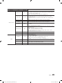
Hotel TV Function
Category
Item
initial value
Widget Mode
ON
Solution Type
Widget Solution
Description
• ON : The TV mode is changed to the Widget mode that TV accesses to the
hospitality server through IP connection and the guest uses various services
and features through Widget of TV
• OFF : The TV mode becomes normal the hospitality mode.
Select the the type of the solution server installed in your site for the widget service.
• Vendor Server : in the case of that the special SI vendor of the server is
installed in your site.
Vendor Server
• SINC Server : in the case of that the Samsung SINC server is installed in your
site.
Server URL Setting
if this item is entered into, URL of the solution server can be inputted.
License Server IP
Setting
if this item is entered into, URL of the license server can be inputted.
ON
• ON : The IPTV mode that watches the broadcasting through the IP network
is enable.
• OFF : The IPTV mode is not disable
Virtual Standby
OFF
TV can supply the main feature in the standby mode if The TV mode is set to the
Virtual Stanby mode.
• ON : The Virtual Standby mode is enable.
• OFF : The Virtual Standby mode is disable.
When Virtual Standby is On, TV power consumption will be 9.5W to 17.4W
(Depending on ithe size of the TV screen).
Instant On
OFF
The fast TV booting mode On/Off.
IPTV Mode
Room Num Setting
set the room number
DRM Mode
Pro:idiom
PI AES Data
0xD27B
PI AES Log
OFF
View PI AES Log
…
DRM
Configures DRM support.
OFF : Turns off DRM support.
LYNK DRM : Select to turn on S-LYNK DRM CAS support only.
Pro:idiom : Select to turn on Pro:Idim CAS support only.
LYNK DRM,PI : Select to have the TV support S-LYNK DRM CAS and Pro:Idiom CAS.
Displays the current state of Pro:Idion AES
• ON : Output of Pro:Idiom AES log is enable.
• OFF : Output of Pro:Idiom AES log is disable.
if this item is entered into, the Pro:Idiom AES log is displayed.
English
[HC890V_ZA]Install_Guide_00ENG.indd 29
29
2014-07-10
3:31:56
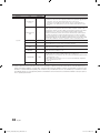
Hotel TV Function
Category
Item
Self Diagnosis
for TV
Self Diagnosis for
HTV
initial value
Description
…
• Enter Self Diagnosis Menu.
Picture Test: Use to check for picture problems. If the problem appears in the
test picture, select Yes and follow the directions on the screen.
• Sound Test: Use the built-in melody sound to check for sound problems. If
the problem occurs during the test, select Yes and follow the directions on the
screen.
…
Lets you check the state of Pro:Idiom and its communication with the SI STB
or SBB. If you have any problems with the Pro:idiom encryption channel or the
communications with the SI STB or SBB, use this diagnosis function. If Pro:Idiom
DTV Channel Key Loss appears to have failed and the Pro:Idim encryption
channel has failed to play content, first check the broadcasting systems related
to Pro:Idiom encryption. If your broadcasting system does not have a problem,
contact Samsung Service. If STB SI Vendor Setting appears to have failed and
communication with the SI STB or SBB has failed, first check your SI STB or SBB.
If your SI STB or SBB does not have a problem, contact to Samsung Service.
SW Update
…
Service Pattern
OFF
Lets you check the state of the TV picture by displaying picture test patterns.
Press the Menu button to turn off the test patterns and exit.
ATV Cable AGC
Gain
Default
Lets you control the AGC gain of the analog cable channels. Don't change the
default value unless problems occur.
DTV Open Cable
AGC Gain
Default
Lets you control the AGC gain of the digital cable channels. Don't change the
default value unless problems occur.
System
Sound Bar Out
TV reset
OFF
Lets you upgrade the TV SW with a USB memory stick. See Page 37.
If the Samsung Sound Bar device is connected to this TV, this item lets you to
select where the TV sound is outputted when the TV is turned on.
• ON : When the TV is turned on, the TV sound is automatically outputted in the
Sound Bar device only.
• OFF : When the TV is turned on, the TV sound is automatically outputted in
the TV speaker device only.
See page 39.
Returns all settings on the TV to their factory defaults.
✎✎REACH (Remote Enhanced Active Control for Hospitality) is a professional, interactive remote controller that lets you
deliver TV firmware updates, cloning data, channel maping changes, REACH contents, and TICKER contents through
RF DTV to several hundred hospitality TVs simultaneously. The REACH functions are avalible only in standalone mode.
The REACH Server is sold separately. Refer to the REACH server manual enclosed with the REACH server product for
more operating information.
30
English
[HC890V_ZA]Install_Guide_00ENG.indd 30
2014-07-10
3:31:56
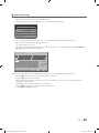
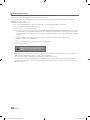
¦¦ Welcome Message
The Welcome Message feature displays a custom message on the TV every time it is turned on.
–– Welcome message settings are in the Hotel Option Menu.
–– Set Welcome Message to ON to display the message when the TV is powered on.
Welcome Message
OFF
Edit Welcome Message
Hospitality Logo
OFF
Hospitality Logo DL
...
Logo Display Time
...
–– You can make the Welcome Message up to 25 characters long and edit it in the Hotel Service menu.
–– Welcome Message supports the following characters:
✎✎ Capital Letters from A to Z.
–– You can edit the Welcome Message by using the remote's navigation, color, and Enter buttons in the “Edit Welcome
Message” OSD (See the illustration below.)
Edit Welcome Message
W
E
R
L
C
H
O
O
M
T
E
E
T
L
O
O
U
_
A BC D E FG
a Move to Left
H IJKLMN
b Move to Right
O PQ R S TU
{ Leave Black
} Done
V WX Y Z
Move Enter
Return
Below are the general directions for navigating and changing letters on the Edit Welcome Message screen:
–– Press the a button on the remote to move to the left in the message.
–– Press the b button to move to the right.
–– After you have selected a position in the message, use the arrow buttons on your remote to select a letter in the
alphabet below the message.
–– Press Enter to place a letter into the position you selected.
–– Press the { button to erase a letter in a position or enter a blank.
–– Press Return or the } button to exit.
English
[HC890V_ZA]Install_Guide_00ENG.indd 31
31
2014-07-10
3:31:56
¦¦ Hotel Logo
The Hospitality Logo function displays the Hotel's picture image when the TV is powered on.
–– Hospitality Logo settings are the Hotel mode menus.
–– The Logo Download and Logo Display Menu items are enabled when you turn the Hospitality Logo option on.
–– If there is a logo image stored in memory and the Hospitality Logo option is on, the Hospitality logo is displayed when
the TV is turned on.
–– The Hospitality logo is not displayed when the Hospitality found Logo option is off, even if the logo image has been
loaded into the TV.
Hospitality Mode
Standalone
SI Vendor
Power On
OFF
Widget Solution
DRM
Service
Channel
MyChannel
Welcome Message
Menu OSD
Music Mode
Remote Jack Pack
External Source
ON
Edit Welcome Message
Clock
Hospitality Logo
r
ON
Hospitality Logo DL
...
Logo Display Time
...
Bathroom Speaker
Eco Solution
Logo/Message
Cioning
REACH Solution
Network
yy Hospitality Logo
–– This option lets you choose whether the Hospitality Logo image is displayed or not.
–– Initial value is OFF.
–– Can be set to OFF or ON.
–– When set to ON, the Logo Download and Logo Time Display menu items become accessible.
yy Logo Download
–– This option lets you download the logo image to the TV’s memory from a USB device.
–– A wait message appears while the image is being copied to the TV.
–– A "completed" message appears when the copy operation finishes successfully.
–– The word "failed" appears if the copy operation was unsuccessful.
–– No USB appears if no USB device is connected.
–– No File appears if there is no file to copy on the USB device or the file is in the wrong format (must be a BMP or AVI
file). If No File appears and there is a logo file on the USB device, check the file format.
yy Logo File Format
–– The TV supports only BMP and AVI format.
–– The file name must be samsung.bmp or samsung.avi.
–– The maximum resolution of the BMP format is 960 x 540.
–– The maximum file size for AVI format is 30MB.
–– The TV does not change the size or scale of the image.
32
English
[HC890V_ZA]Install_Guide_00ENG.indd 32
2014-07-10
3:31:57
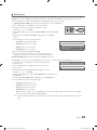
¦¦ USB Cloning
The USB Cloning function lets you download user-configured settings (Picture, Sound, Input, Channel, Setup, and Hotel
Setup) from one TV to a USB device, and then upload these settings from the USB device to other TV sets. This lets you
create a standard file of settings and distribute that standard file to all the TVs in your facility.
yy Cloning from TV to USB: Copies stored menu settings from a TV to a USB device.
1.Insert a USB drive into the USB port on the rear of the TV.
2.Enter the hotel option menu by pressing buttons in order.
MUTE → 1 → 1 → 9 → ENTER
3.Press the ▲ or ▼ button to select Clone:TV to USB, and press the ENTER
button.
4.When the message Clone: TV to USB is displayed. Press the ENTER
button.
5.The TV displays one of the following messages:
▪▪ In Progress: Copying data to USB.
▪▪ Completed: Copy was successful.
▪▪ Failed: Copy was not successful.
▪▪ No USB: USB is not connected.
The clone folder will be labeled T-MST14AKUCB.
Clone TV to USB
Clone USB to TV
Setting Auto Initialize
OFF
✎✎The cloned values include the values on the Guest side menu
(brightness, picture size, contrast, etc.) and the Hotel side menu.
Cloning from USB to TV: Copies menu settings in a USB device to a TV.
✎✎Shortcut: Turn the TV off, insert the USB device, turn the TV on, and then press the ENTER button for 5 seconds.
To clone data to the TV using the Hotel menu, follow these steps:
1.Turn the TV off.
Clone TV to USB
2.Insert the USB drive into the USB port on the rear of the TV.
Clone USB to TV
3.Turn the TV on.
Setting Auto Initialize
OFF
4.Enter the Interactive menu by pressing these buttons in order.
MUTE → 1 → 1 → 9 → ENTER
5.Press the ▲ or ▼ button to select “Clone: USB to TV”, and then press the
ENTER button.
6.The message Clone: USB to TV is displayed. Press the ENTER button.
7.The TV displays one of the following messages:
▪▪ In Progress: Copying data to TV.
▪▪ Completed: Copy was successful.
▪▪ Failed: Copy was not successful.
▪▪ No USB: USB is not connected
▪▪ No File: There is no file to copy on the USB device. If you get a No File message, check the folder on your USB
device. The folder name should be T-MST14AKUCB.
✎✎ Tables that list lthe settings that are cloned in the Interactive and Standalone Hotel Menus begin on the next
page.
English
[HC890V_ZA]Install_Guide_00ENG.indd 33
33
2014-07-10
3:31:57
yy Settings Cloned in the Hotel Menu
Menu Item
Cloning Support
Hospitality Mode
Yes
SI Vendor
Yes
Power On Channel
Yes
Power On Channel Num
Yes
Power On Channel Type
Yes
Power On Volume
Yes
Power On Volume Num
Yes
Min Volume
Yes
Max Volume
Yes
Power On Source
Yes
Power On Option
Yes
Channel Setup
N/A
Channel Editor
N/A
Dynamic SI
Yes
Picture Menu Lock
Yes
Menu Display
Yes
Panel Button Lock
Yes
Home Menu Display
Yes
Home Menu Editor
Yes
Home Menu Auto Start
Yes
Clock Type
Yes
Local Time
Yes
Music Mode AV
Yes
Music Mode Comp
Yes
Music Mode Backlight
Yes
Priority AV
Yes
Priority HDMI
Yes
AV Option
Yes
HDMI Option
Yes
HDMI Music Mode
Yes
USB Pop-up Screen
Yes
External Source Banner
Yes
Auto source
Yes
Anynet+Return Source
Yes
Sub Amp Mode
Yes
Sub Amp Volume
Yes
Energy saving
Yes
Welcome Message
Yes
Edit Welcome Message
N/A
Hospitality Logo
Yes
Hospitality Logo DL
N/A
34
English
[HC890V_ZA]Install_Guide_00ENG.indd 34
2014-07-10
3:31:57
Menu Item
Cloning Support
Logo Display Time
Yes
Clone TV to USB
N/A
Clone USB to TV
N/A
Setting Auto Intialize
Yes
REACH 3.0
Yes
REACH 2.0
Yes
REACH Channel
Yes
Group ID
No
IPG Room Type
No
TICKER
Yes
REACH Update Time
Yes
REACH Update Immediate
Yes
Room Number
Yes
REACH 2.0 TV Sound
Yes
REACH 2.0 Server Version
N/A
Network Setup
N/A
SmartHub Model Setting
Yes
SmartHub Setting
N/A
Widget Mode
Yes
Solution Type
Yes
Server URL Setting
Yes
License Server IP Setting
Yes
IPTV Mode
Yes
Virtual Standby
Yes
Instant On
Yes
Room Num Setting
N/A
DRM Mode
Yes
PI AES Data
N/A
PI AES Log
Yes
View PI AES Log
N/A
Self Diagnosis for TV
N/A
Self Diagnosis for HTV
N/A
SW Update
N/A
Service Pattern
Yes
ATV Cable AGC Gain
Yes
DTV Open Cable AGC Gain
Yes
Sound Bar Out
Yes
TV reset
N/A
English
[HC890V_ZA]Install_Guide_00ENG.indd 35
35
2014-07-10
3:31:57
¦¦ Multi Code Remocon
A Multi Code Remocon is a special remote which is designed to control multiple TVs.
This function is useful where there is more than one TV in a location.
You can control up to 10 TVs with a different ID code of each remote with no conflicts between the TVs. ID numbers are
displayed on each TV's OSD.
The Initial ID code for each TV is “0”.
–– You can set and reset the ID code in Analog TV mode or PC mode. (Not available in DTV mode.)
–– You can set the ID code to any digit from 0 to 9.
–– To set a TV's ID code, follow these steps:
1. Aim the remote at the TV, and then press the MUTE button and the RETURN button simultaneously for more than
7 seconds. When you stop pressing the buttons, the TV displays the current ID in the middle of the screen and the
words, "Remote control code is set to x. If you want to change the Remote control code, enter the digit you want to
change."
2. Press the number on the remote you want to assign to the TV. The TV displays the following words:
"Remote control code is changed to x."
✎✎ The TV will display the OSD until you press the Exit button.
See the example below.
Remote control code is set to 0. If you want to change
Remote control code, enter the digit you want to
change.
Example: After you see the message above, if you press 1, the TV and Remote will be set to ID code 1. The TV then
displays the following message: “Remote control code is changed to 1”
The TV can then only be controlled by a remote which has the same ID code (1).
–– To reset the ID code, press the MUTE button and the EXIT button simultaneously for more than 7 seconds. When
you stop pressing the buttons, the ID codes of the TV and Remote are reset to “0”. “Remote control code is set to 0.”
appears on the TV
36
English
[HC890V_ZA]Install_Guide_00ENG.indd 36
2014-07-10
3:31:57
¦¦ Setting Auto Initialize
When you clone settings from one TV to another, you clone both the guest side menu and hotel side menu settings: Picture,
Sound, Input, Channel, Setup, and Hotel Setup. This lets you set nearly all of the menu values on your hospitality TVs to
the same, standard settings. If you allow guests access to the guest side menus, for example the Picture menu, they can
change the settings in those menus so they are no longer standard. If you set the Setting Auto Initialize function to on the TV
automatically restores (initializes) any guest-side menu values to the cloned, standard values when the TV is turned off and then
turned on again. Note that Setting Auto Initialize works on cloned guest side menu values only. Settings which have not been
cloned are ignored.
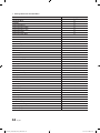
The table below lists the settings that are restored to their cloned values when you set the Setting Auto Initialize function to On.
Menu
Picture
Sound
Menu Item
Picture Mode
Back light
Contrast
Brightness
Sharpness
Colour
Tint (G/R)
Apply Picture Mode
Picture Size
Picture Size
Position
PIP
Advanced Settings
Dynamic Contrast
Black Tone
Flesh Tone
RGB Only Mode
Colour Space
White Balance
10p White Balance
Gamma
Expert Pattern
Motion Lighting
Picture Options
Colour Tone
Digital Clean View
MPEG Noise Filter
HDMI Black Level
Film Mode
Auto Motion Plus
Picture Off
Reset Picture
Sound Mode
Sound Effect
Virtual Surround
Dialog Clarity
Equaliser
Speaker Settings
Additional Settings
Audio Format
Audio Delay
Auto Volume
Reset Sound
Menu
System
Menu Item
Accessibility
Voice Guide
Visual Impaired
Caption
Menu Transparency
High Contrast
Menu Language
Smart Touch Control Settings
Touch Sensitivity
Onscreen Remote Size
Voice Control
Language
TV Voice
Voice Gender
Notifications
Device Manager
Keybord Settings
Mouse Settings
Time
Clock
Sleep Timer
Eco Solution
Energy Saving
Eco Sensor
No Signal Power Off
Auto Power Off
Smart Security
Auto Protection Time
Change PIN
General
Game Mode
BD Wise
Sound Feedback
Boot Logo
Instant On
Anynet+ (HDMI-CEC)
Anynet+ (HDMI-CEC)
Auto Turn Off
DivX® Video On Demand
English
[HC890V_ZA]Install_Guide_00ENG.indd 37
37
2014-07-10
3:31:58
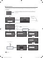
¦¦ Hotel Plug & Play
The Hotel Plug & Play function, which automatically performs the Hotel mode selection, Country Setup, Clock Setup, and
Picture Mode Setup, runs once, when power is first turned ON. Setup also runs automatically after you have executed a
Service Reset.
yy UI Scenario
If you select Factory Reset, the TV resets all values to their factory defaults and
then displays the Hospital Plug & Play menu. Go to the first Hospital Plug & Play
screen below.
Self Diagnosis for TV
Self Diagnosis for HTV
SW Update
Service Pattern
OFF
ATV Cabel AGC Gain
Default
DTV OpenCable AGC Gain
Default
Sound Bar Out
OFF
Contact Samsung
TV Reset
E+P
Local Set
Local Set
If you select
Change
Change
LocatSet
Setif ifLocated
Locatedinin North
North America,
Europe.
Change
Locat
America,Latin
LatinAmerica
Americaand
and
Europe.
otherregions,
regions,Please
Pleasepress
press SKIP button
step.
In In
other
buttonmove
movetotothe
thenext
next
step.
Warning! TV might not function if local set is not correctly configured.
When Local set is changed, TV Will restart automatically to apply it.
E
Skip
Skip
If you select
Skip
E
US
Current Localset
Localset :: US
Current
US
Change
Change
If you change the
country of the Current
Location
The TV is automatically turned
off and on.
Countries List
USA
If you don't change the country of
the Current Location
E
Start
Easy Set Up
If you select
Standalone Only
Interactive
Set-Back Box will control TV functions.
Standalone Plug & Play
After Plug & Play is completed, TV will be set to Standlone mode.
Sets TV to Standalone mode and exit Plug & Play immediately after.
If you select
Standalone
Plug&Play
TV will enter the RF mode.
E
Standalone Only
If you select
Interactive Only
E
Interactive
Hospitality Option Menu
appears.
E
Welcome to Samsung TV
Configure your TV
Select your language to start the on
screen setup.
Select your information in the categories below.
Picture Mode
English
Standard
Español
Français
Press the ▲▼◄► buttons
to move the highlight.
Press the enter button
to select.
Press Power OFF to exit.
E
Auto Program
Choose a picture
mode that best
suits your viewing
environment.
E
To receive channels, configure the options
below then select Scan.
Antenna
E
Select the connected
antenna.
Cable
Digital Cable System
STD
Analog Cable System
STD
Scan
Select your language
Select Picture mode
Select the channel band to
use for Auto Program
E
Auto Tuning
Auto Program is finding channels for you...
Cable 4
40%
Digital Cable
Analogue
0
0
Press Power OFF to exit.
Stop
After Searching
channels.
E
Clock
TV Setup Complete!
You can adjust your time to set DST, Time Zone
and clock mode
Your TV is now ready to use
Standalone Hospitality
Option Menu appears.
Clock Mode
Date
E
E
OK
E
Time
DST
Time Zone
Set current date and time
Auto
-- / -- / ----- : -- -Off
Eastern
-- : -- --
Select Clock Mode, DST, and your Time Zone
38
English
[HC890V_ZA]Install_Guide_00ENG.indd 38
2014-07-10
3:31:58
yy Hotel Plug & Play OSD
–– Initially highlighted: Interactive
–– If you select the Standalone Only button, the Standalone hotel mode is set by default and the “Standalone mode is set”
OSD appears for 3 seconds.
TV enters RF mode automatically after displaying the “Standalone mode is set” OSD for 3 seconds.
–– If you select the Interactive mode, the Interactive Setup Menu is displayed. Press the power off key to exit from the
Interactive menu.
–– If you select the Standalone Plug & Play mode, the “Select Menu Language” OSD appears.
yy LocalSet
–– Initially highlighted: US
–– If you press the Enter key after selecting Change, you can change the country.
–– If the country is changed, the TV automatically turns off and on.
–– If you select the Interactive mode, the Interactive Setup Menu is displayed. Press the power off key to exit from the
Interactive menu.
–– If you select the incorrect country, execute TV Reset again after entering the System section of the Hotel Menu.
yy Select Menu Language OSD
–– If you select Standalone from the “Select Hotel TV Mode” OSD, the “Select Menu Language” OSD appears.
–– Initially highlighted: English
–– Display time: OSD time out and operation are the same as Samsung's consumer TV models.
–– If you press the Enter key, the “Picture Mode” OSD appears
yy Picture Mode OSD
–– Initially highlighted: Standard.
–– The TV displays the Picture Mode OSD where you can choose the Dynamic or a Standard Picture mode.
yy Auto Search Mode OSD
–– If you press the Enter key, the TV automatically searches for channels.
–– The OSD Display time, which starts when the Auto Store operation is completed and continues until the Auto Sort
function starts, is 30 seconds.
yy Set Clock Mode, DST(Daylight saving time), and Time Zone OSD
–– Initially highlighted:
Clock Mode : Auto, DST : Off, Time Zone : Eastern
–– If the TV will be tuned to digital broadcast channels, and these channels transmit date and time information, set the
Clock Mode to Auto. The TV will set the date and time automatically.
–– If the TV will not be tuned to digital broadcast channels, set the Clock Mode to Manual, and then set the date and time
on the TV manually.
–– Set DST On or Off to apply or not apply daylight saving time to the TV.
–– Select your time zone on the map that appears.
English
[HC890V_ZA]Install_Guide_00ENG.indd 39
39
2014-07-10
3:31:58
¦¦ USB Software Upgrade Method
Samsung may offer upgrades to the TV’s SW in the future. Please contact the Samsung Hospitality Hot line at 1-866-8940524 to receive information about downloading upgrades and using a USB drive to update the SW by connecting the USB
drive containing the upgrade to the USB port located on the TV.
When the software is upgraded, video and audio settings you have made will return to their default (factory) settings. We
recommend you clone the hospital settings so that you can easily reset them after the upgrade.
To upgrade the TV's software, follow these steps:
1.Insert a USB drive containing the SW upgrade into the USB port on the side of the
TV.
2.Press the MENU button to display the menu.
Press the ▲ or ▼ button to select Support, and then press the ENTERE button.
3.Press the ▲ or ▼ button to select SW Upgrade, and then press the ENTERE
button.
The message "Scanning for USB. This may take more than 1min." is displayed.
4.The message "Upgrade version XXXX to version XXXX? The system will be reset
after upgrade." is displayed.
Press the ◄ or ► to select OK, and then press the ENTERE button.
Please be careful to not disconnect the power or remove the USB drive while upgrades are being applied. The TV will turn off
and turn on automatically after completing the SW upgrade. Please check the SW version after the upgrades are complete.
¦¦ Soundbar(AirTrack)
yy Samsung Soundbar(AirTrack) and Hospitality TVs in 2014
–– Samsung Soundbar(AirTrack) and hospitality TVs support the HDMI ARC feature If you connect a compatible Samsung
Soundbar(AirTrack) to a compatible Samsung hospitality TV using a single HDMI cable, guests can listen to the TV's
sound through the Soundbar(AirTrack).
–– The item of Soundbar(AirTrack) Out in Hospitality Option Menu makes you control to where the TV sound is outputted
when the TV is turned on.
If Sound bar Out is On, the TV sound is automatically outputted in the Soundbar(AirTrack) device only whenever TV is
turned on.
If Sound bar Out is Off, the TV sound is automatically outputted in the TV speaker only whenever TV is turned on.
–– Samsung Soundbar(AirTrack) products compatible with Samsung Hospitality TV through the HDMI ARC function are
more than 4 series models having been launched from 2012.
yy Setting the Soundbar(AirTrack) to Hotel Mode.
1. Set the following Hotel menu options:
––
––
––
––
Hotel option > External Device > Sound Bar Out = On.
Hotel option > Power On > Power On Volume = User Defined.
Hotel option > Power On > Power On Volume Num > Set greater than 0.
Hotel option > Power On > Max Volume > Set greater than 0.
2. Connect an HDMI cable from the HDMI OUT jack on the back of the Soundbar(AirTrack) to the HDMI2 port (supporting
ARC) on the hospitality TV.
3. After the Soundbar(AirTrack) is connected to the hospitality TV, when the TV turns on, the Soundbar(AirTrack)
automatically detects the TV, and then automatically switches to Hotel Mode.
Soundbar(AirTrack) Hotel mode functional characteristics:
yy
yy
yy
yy
yy
40
Power On/Off is synchronized with the TV
HDMI_CEC defaults set to On
Functions through the “HDMI OUT” port only
Disables the "Input mode" key on the VFD to prevent unexpected audio-source changes.
Acquires adjustable Power On and Max Volume settings from the TV’s Hotel option menu. Soundbar's Power
On Volume and Max Volume values, however, are ½ of Power On Volume and Max Volume settings in the TV's
Hotel option menu. Example: If the TV's Power On Volume=20 and Max Volume=90, then Soundbar's Power On
Volume=10 and Max Volume=45.
English
[HC890V_ZA]Install_Guide_00ENG.indd 40
2014-07-10
3:31:59
¦¦ Channel Bank Editor (Smoovie TV Only)
The Channel Bank Editor in conjunction with the SMOOVIE remote lets you control the channels guests have access to. The
Channel Bank Editor provides three Banks of channels and lets you select which channels will be available from each bank.
SMOOVIE remotes have instalable Bank Cards which correspond to the channel banks in the Channel Bank Editor. The
remotes only allow access to channels in the channel bank that correspond to the installed card. Consequently, the channels a
guest can access depend on the Bank Card installed in their SMOOVIE remote.
Setting the Channel Bank Editor under Stand-alone Mode
1. Press MUTE+1+1+9+EnterE on the remote to enter the Hotel Standalone menu.
2. Go to SI vendor, and then select : “Smoovie”
3. Find the new menu option, "Channel" → "Channel Bank Editor".
4. Enter the “Channel Bank Editor”.
Hospitality Mode
SI Vendor
Standalone
OFF
Widget Solution
DRM
d
SI Vendor
Smoovie
d
SI Vendor
Smoovie
d
SI Vendor
Smoovie
▪▪ <Depending on model and region, some menu items may not exist.>
5. Edit the Channel Bank. An example is below.
a. Bank1 (Free channel): Select the channels that will be accessible when a remote doesn’t have a card.
b. Bank2 (Family Card - Green): Select the channels that will be accessible when a remote has a GREEN CARD.
c. Bank3 (Adult Card - Red): Select the channels that will be accessible when a remote has a RED CARD.
Channel Bank Editor
Bank1 (4)
Bank2 (6)
Bank3 (36)
All
1 ABC
2 CBS
3 FOX
4 NBC
5 CNN
6 CW
7 HBO
8 TNT
Move
Select/Deselect
Return
Information About SMOOVIE Remote Controls
yy
yy
yy
yy
yy
If you select SMOOVIE as the SI vendor, you should also use SMOOVIE remotes in your facility.
Guests with remotes that do not have a card can only view channels from Bank 1.
Guests using the Numeric keys on the remote to change channels can only view channels from Bank 1.
Guests with remotes that have Green or Red cards must use the channel up/down keys to change channels.
Guests can only see channels from the Bank1 channel list In the Channel Guide or the Channel List.
English
[HC890V_ZA]Install_Guide_00ENG.indd 41
41
2014-07-10
3:31:59
Smoovie Set Up Sequence
Smoovie TV Setup (Air/ Cable )
Only Air or Cable used
Only Air or Cable used
If the TV starts with Hotel Plug&Play
If Hotel Plug&Play already done
1
Do a complete P&P (including Air or Cable auto tune)
Enter the Hotel menu
2
After P&P, the TV displays the Hotel menu
Select the channel type
- ATV or ADTV for Air
- CATV or CDTV for cable
3
Select the channel type
- ATV or ADTV for Air
- CATV or CDTV for cable
Select Smoovie TV in the Hotel menu
4
Select Smoovie TV in the Hotel menu
Select Channel Setup
5
Select Channel Setup
(Can be skipped)
Select "Air" or "Cable" to auto tune
6
Select "Air" or "Cable" to auto tune. (Can be skipped,)
Set up channels in the CH Bank Editor
7
Set up channels in the CH Bank Editor
After power off & on, guests can use the TV
8
After power off & on, guests can use the TV
Step
9
10
¦¦ Channel Editor
The Channel Editor lets you edit the channels stored in the TV's memory. Using Channel Editor you can:
–– Change the channel numbers and names, and sort the channels in your desired channel number order.
–– Apply the video mute to channels you select. The vido mute blanks out the video from a channel and outputs only the sound
while displaying a speaker icon on the screen.
The Channel Editor also lets you view information about each channel easily, without your having to display each channel
directly.
Hospitality Mode
SI Vendor
Standalone
OFF
Power On
Widget Solution
DRM
Service
Channel
MyChannel
Menu OSD
Clock
Music Mode
r
Remote Jack Pack
External Source
Channel Editor
Bathroom Speaker
Eco Solution
Logo/Message
Cioning
REACH Solution
Network
▪▪ <Depending on model and region, some menu items may not exist.>
General Steps for Using the Channel Editor in Stand-alone Mode
42
Step
Broad Outline
1
2
3
4
5
Run ‘Channel Auto Store’ in the Hotel Option Menu.
Enter ‘Channel Editor’ in the Hotel Option Menu.
On a piece of paper, compile a list of channels you want to have, arranged in the order you want.
Rearrange channels and edit channel names with the TOOLS Button based on the list you compiled.
Press the EXIT or RETURN Button to exit.
<For a detailed explanation of how Channel Editer works, see pages 41 through 44.>
English
[HC890V_ZA]Install_Guide_00ENG.indd 42
2014-07-10
3:31:59
The picture below shows a sample Channel Editor screen.
Channel
All
a Delete
b Select All
a2
----- (Cable)
a 10
a3
----- (Cable)
Air 10-1
CW
CW DTV
a4
----- (Cable)
a 11
HBO
a5
----- (Cable)
Air 11-1
HBO DTV
a6
----- (Cable)
a 12
NBC
a7
ABC
Air 12-1
NBC DTV
Air 7-1
ABC
a 13
----- (Cable)
CNN
a8
FOX
a 14
Air 8-1
FOX DTV
Air 15
----- (Cable)
a9
----- (Cable)
a 16
TNT
} Video Mute On
` Information
U Page
E Select
T Tools
R Return
yy a Indicates an analog channel.
yy Channels without an a are digital channels.
✎✎ If Dynamic SI in the Hospitality Option Menu is On, Channel Editor will display no digital channels. You must set
Dynamic SI to Off before you can edit digital channels in Channel Editor.
yy The guide at the bottom of the Channel Editor menu displays the remote buttons you need to press to apply Channel
Editor functions.
1 Using the remote's up or down arrow key, highlight the channel that you want to edit.
–– To edit more than one channel, move the highlight to a channel, and then press the ENTERE key. A check will
appear in the check box next to the channel. Repeat for each channel you want to edit.
2 To delete the channel or channels you selected from the channel list, press the red button on the remote.
–– To delete two or more channels simultaneously, select multiple channels in Step 1, and then press the red button
on the remote.
3 Press the green button on the remote to select all channels.
4 To apply the video mute, press the yellow button on the remote.
–– To apply the video mute to two or more channels simultaneously, select multiple channels in Step 1, and then press
the yellow button on the remote.
5 To view information about a channel, including video mute set up, press the INFO button on the remote.
6 Press the TOOLS button on the remote to rename a channel or change the channel number. See page 43.
Channel Editor Functions and Remote Button
a Red (Delete): Deletes a channel from the channel list.
b Green (Select All): Selects all channels at once.
{ Yellow (Deselect All): Deselects all channels at once.
} Blue (Video Mute On/Off): You can set the Video Mute On/Off.
U (Page): Moves to next or previous page.
` (Information): Display details of the selected channel.
T (Tools): Displays the option menu.
R (Return): Returns to the previous step or exits.
English
[HC890V_ZA]Install_Guide_00ENG.indd 43
43
2014-07-10
3:31:59
When you press the TOOLS button, the following menu is available.
Channel
TOOLS
All
a Delete
b Select All
a2
----- (Cable)
a 10 Number CW
Edit Channel
a3
----- (Cable)
a4
----- (Cable)
a5
----- (Cable)
AirChannel
10-1
Rename
a 11
Information
Air 11-1
a6
----- (Cable)
a 12
CW DTV
HBO
HBO DTV
NBC
a7
ABC
Air 12-1
NBC DTV
Air 7-1
ABC
a 13
----- (Cable)
CNN
a8
FOX
a 14
Air 8-1
FOX DTV
Air 15
----- (Cable)
a9
----- (Cable)
a 16
TNT
} Video Mute On
` Information
U Page
E Select
T Tools
R Return
R Return
yy Edit Channel Number
Edit Channel Number
Use Edit Channel Number to change the channel number of a channel you select.
To change a channel number, follow these steps:
1. Select a channel on the Channel Edit screen.
2. Press the TOOLS button on your remote.
3. Select Edit Channel Number in the Tools menu.
4. Use the up or down arrow keys to change the channel number.
5. Select OK when done, and then press the ENTERE button.
✎✎ When you change the channel number, the channel information is not updated automatically.
4
Cancel
U Adjust
yy Rename Channel
Use Rename Channel to change the name of a channel you select.
To change the name of a channel, follow these steps:
1. Select a channel on the Channel Edit screen.
2. Press the TOOLS button on your remote.
3. Select Rename Channel in the Tools menu.
4. Use the on-screen keyboard that appears to enter the new name for the channel. Use the arrow
buttons on your remote to select a letter or number, and then press Enter. Repeat for each letter
or number you want to select.
5. When finished, select Done on the bottom of the screen, and then press the ENTERE button.
Ok
ABC HD_
E Space
Rename Channel
Enter new name for CH 4 (Max Length = 24)
ABC HD_
a
b
c
d
e
f
1
2
3
g
h
i
j
k
l
4
5
6
m
n
o
p
q
r
7
8
9
s
t
u
v
w
x
y
z
0
◄
►
A/a
Space
Done
Cancel
a Delete
yy Information
Use Information to view information about a channel you select.
To view information about a channel, follow these steps:
1. Select a channel on the Channel Edit screen.
2. Press the TOOLS button on your remote.
3. Select Information in the Tools menu.
4. Select OK, and then press the ENTERE button to close the Information screen.
44
R Return
{ Space
R Return
Information
OK
English
[HC890V_ZA]Install_Guide_00ENG.indd 44
2014-07-10
3:32:00
The external sources of this TV are displayed in the last page of the Channel Editor menu as shown in the example below.
In the example, there are two external sources connected to the TV, HDMI2 and AV.
–– You can assign a new analog channel to an external source by selecting the source on the last page, pressing the TOOLS
button, selecting Edit Channel Number, and then using the up or down arrow button on the remote to select the channel
number of the analog channel.
–– If you tune to a channel after assigning the channel to an external source, you can enter the external source without opening
the TV source menu.
Channel
All
a 628
MLS Soccer
a 629
CNN NEWS
a 812
American Idol
a 840
90210
a 841
LOST
a 998
Euro Football
a
HDMI1
a
HDMI2
a
HDMI3
a
AV
b Select All
U Page
E Select
T Tools
R Return
After assigning channel number 997 to the
AV source.
Channel
All
a 628
MLS Soccer
a 629
CNN NEWS
a 812
American Idol
a 840
90210
a 841
LOST
a 997
AV
a
Euro Football
a
HDMI1
a
HDMI2/DVI
a
HDMI3
a Delete
b Select All
U Page
E Select
T Tools
R Return
English
[HC890V_ZA]Install_Guide_00ENG.indd 45
45
2014-07-10
3:32:00
Installing the Wall Mount
If you mount this product on a wall, it should be mounted only as recommended by the manufacturer.
Unless it is correctly mounted, the product may slide or fall, causing serious injury to a child or adult, and
serious damage to the product.
Installing the Wall Mount Kit
The wall mount kit (sold separately) lets you mount the TV on the wall.
To assemble the wall mount, use the styrofoam that came with the TV's packaging to protect it. Lay the TV down and attach
the screws.
For detailed information about installing the wall mount, see the instructions provided with the wall mount kit. We recommend
you contact a technician for assistance when installing the wall mount bracket. We do not advise you to do it yourself.
Samsung Electronics is not responsible for any damage to the product or injury to yourself or others if you select to install the
wall mount on your own.
To order the wall mount kit, contact Samsung Customer Care at 1-800-SAMSUNG (1-800-726-7864).
Installing a Wall Mount Using the Wall Mount Adapter
Before installing any wall mount kit, install the wall mount adapters provided with the TV.
–– Refer to the Installation Manual included with the Samsung wall mount kit.
Wall mount
Bracket
TV
Wall mount
Adapter
C
46
English
[HC890V_ZA]Install_Guide_00ENG.indd 46
2014-07-10
3:32:01
VESA Wall Mount Kit Notes and Specifications
Install your wall mount on a solid wall perpendicular to the floor. Before attaching the wall mount to surfaces other than plaster
board, please contact your nearest dealer for additional information. If you install the TV on a ceiling or slanted wall, it may fall
and result in severe personal injury.
When using a third-party wall mount, note that the assembling screw length(C) is shown below.
Product
Family
LED-TV
[Curved]
TV size in
inches
VESA screw hole
specs
(A * B) in millimeters
55
C (mm)
Quantity
M8
4
21.7 ~ 26.7
400 X 400
65
Standard
Screw
21.5 ~ 26.5
Do not install your Wall Mount Kit while your TV is turned on. It may result in personal injury from electric shock.
–– Standard dimensions for wall mount kits are shown in the table.
–– Samsung wall mount kits contain a detailed installation manual, and all parts necessary for assembly are provided.
–– Do not use screws that do not comply with VESA standard screw specifications.
–– Do not use screws that are longer than the standard length or do not comply with VESA standard screw specifications.
Screws that are too long may cause damage to the inside of the TV set.
–– For wall mounts that do not comply with the VESA standard screw specifications, the length of the screws may differ
depending on the wall mount specifications.
–– Do not fasten the screws too firmly. This may damage the product or cause the product to fall, leading to personal injury.
Samsung is not liable for these kinds of accidents.
–– Samsung is not liable for product damage or personal injury when a non-VESA or non-specified wall mount is used or the
consumer fails to follow the product installation instructions.
–– Do not mount the TV at more than a 15 degree tilt.
–– Always have two people mount the TV on to a wall.
English
[HC890V_ZA]Install_Guide_00ENG.indd 47
47
2014-07-10
3:32:01
Securing the TV to the Wall
Caution: Pulling, pushing, or climbing on the TV may cause the TV to fall. In
particular, ensure your children do not hang on or destabilize the TV. Doing
so may cause the TV to tip over, causing serious injuries or death. Follow all
safety precautions provided in the Safety Flyer included with your TV. For
added stability and safety, you can purchase and install the anti-fall device
as described below.
Installing the TV-Holder Kit:
1. Put the screws into the clamps and firmly fasten them into the wall. Confirm
that the screws have been firmly installed into the wall.
-- You may need additional material such as anchors depending on the type
of wall.
-- Since the necessary clamps, screws, and string are not supplied, please
purchase these additionally.
2. Remove the screws from the centre back of the TV, put the screws into the
clamps, and then fasten the screws into the TV again.
-- Screws may not be supplied with the product. In this case, please purchase screws of the following specifications.
-- Screw Specifications : For a 55 ~ 65 inches: M8
3. Connect the clamps fixed into the TV and the clamps fixed onto the wall with a
strong cable and then tie the string tightly.
-- Install the TV close to the wall so that it does not fall backwards.
-- It is safe connecting the string so that the clamps fixed onto the wall are
equal to or lower than the clamps fixed on the TV.
-- Untie the string before moving the TV.
4. Verify that all connections are properly secured. Periodically check connections
for any sign of damage. If you have any doubt about the security of your
connections, contact a professional installer.
48
English
[HC890V_ZA]Install_Guide_00ENG.indd 48
2014-07-10
3:32:01
Specifications
Environmental Considerations
Operating Temperature
Operating Humidity
Storage Temperature
Storage Humidity
Model Name
50°F to 104°F (10°C to 40°C)
10% to 80%, non-condensing
-4°F to 113°F (-20°C to 45°C)
5% to 95%, non-condensing
HG55NC890V
HG65NC890V
Display Resolution
Screen Size
(Diagonal)
Sound (Output)
Dimensions (WxHxD)
Body
With stand
Weight
Without Stand
With Stand
1920 X 1080
55" Class
(54.6 measured diagonally)
65" Class
(64.5 measured diagonally)
40W (Left:10W, Right:10W, Woofer:20W)
48.5 x 28.0 x 3.5 inches
(1232.8 x 713.3 x 89.8 mm)
48.5 x 29.8 x 9.3 inches
(1232.8 x 759.4 x 236.8 mm)
57.1 x 33.0 x 4.2 inches
(1451.0 x 838.4 x 107.3 mm)
57.1 x 35.1 x 12.1 inches
(1451.0 x 893.7 x 307.8 mm)
38.3 lbs (17.4 kg)
41.6 lbs (18.9 kg)
52.9 lbs (24.0 kg)
59.9 lbs (27.2 kg)
✎✎Design and specifications are subject to change without prior notice.
✎✎This device is a Class B digital apparatus.
✎✎For power supply and power consumption information, refer to the label attached to the product.
English
[HC890V_ZA]Install_Guide_00ENG.indd 49
49
2014-07-10
3:32:02
Display Resolution
When you use your TV as a computer monitor, you can also select one of the standard resolutions listed in the Resolution
column. The TV will automatically adjust to the resolution you choose.
Mode
Resolution
Horizontal Frequency
(KHz)
Vertical Frequency
(Hz)
Pixel Clock Frequency
(MHz)
Sync Polarity
(H / V)
IBM
640 x 350
720 x 400
31.469
31.469
70.086
70.087
25.175
28.322
+/-/+
MAC
640 x 480
832 x 624
1152 x 870
35.000
49.726
68.681
66.667
74.551
75.062
30.240
57.284
100.000
-/-/-/-
VESA DMT
640 x 480
640 x 480
640 x 480
800 x 600
800 x 600
800 x 600
1024 x 768
1024 x 768
1024 x 768
1152 x 864
1280 x 720
1280 x 800
1280 x 1024
1280 x 1024
1366 x 768
1440 x 900
1600 x 900RB
1680 x 1050
1920 x 1080
31.469
37.861
37.500
37.879
48.077
46.875
48.363
56.476
60.023
67.500
45.000
49.702
63.981
79.976
47.712
55.935
60.000
65.290
67.500
59.940
72.809
75.000
60.317
72.188
75.000
60.004
70.069
75.029
75.000
60.000
59.810
60.020
75.025
59.790
59.887
60.000
59.954
60.000
25.175
31.500
31.500
40.000
50.000
49.500
65.000
75.000
78.750
108.000
74.250
83.500
108.000
135.000
85.500
106.500
108.000
146.250
148.500
-/-/-/+/+
+/+
+/+
-/-/+/+
+/+
+/+
-/+
+/+
+/+
+/+
-/+
+/+
-/+
+/+
✎✎NOTE
yy The interlaced mode is not supported.
yy The set might operate abnormally if you select a non-standard video format.
yy Separate and Composite modes are supported. SOG (Sync On Green) is not supported.
50
English
[HC890V_ZA]Install_Guide_00ENG.indd 50
2014-07-10
3:32:02
Dimensions
▪▪ Front view / Side view
HG55NC890 / HG65NC890
6
1
2
3
4 5
7
(Unit: inches)
HG55NC890
1
48.5
2
47.5
3
26.8
4
28.0
5
29.8
6
3.5
7
9.3
HG65NC890
57.1
55.9
31.6
33.0
35.1
4.2
12.1
▪▪ Jack panel detail / Rear view
HG55NC890 / HG65NC890
3
2
1
4
6
5
(Unit: inches)
HG55NC890
1
15.7
2
15.7
3
16.2
4
14.6
5
9.3
6
11.4
HG65NC890
15.7
15.7
20.5
14.5
10.3
11.2
English
[HC890V_ZA]Install_Guide_00ENG.indd 51
51
2014-07-10
3:32:02
▪▪ Base Stand detail
HG55NC890 / HG65NC890
1
3
2
(Unit: inches)
HG55NC890
1
34.0
2
9.3
3
6.2
HG65NC890
38.9
12.1
8.1
NOTE: All drawings are not necessarily to scale. Some dimensions are subject to change without prior notice. Refer to the
dimensions prior to performing installation of your TV. Not responsible for typographical or printed errors.
© 2014 Samsung Electronics America, Inc
52
English
[HC890V_ZA]Install_Guide_00ENG.indd 52
2014-07-10
3:32:02
¦¦ Important Warranty Information Regarding Television Format Viewing
✎✎ See the warranty card for more information on warranty terms.
Wide screen format LED Displays (16:9, the aspect ratio of the screen width to height) are primarily designed to view wide screen format full-motion video.
The images displayed on them should primarily be in the wide screen 16:9 ratio format, or expanded to fill the screen if your model offers this feature and
the images are constantly moving. Displaying stationary graphics and images on screen, such as the dark sidebars on nonexpanded standard format
television video and programming, should be limited to no more than 5% of the total television viewing per week.
Additionally, viewing other stationary images and text such as stock market reports, video game displays, station logos, web sites or computer graphics
and patterns, should be limited as described above for all televisions. Displaying stationary images that exceed the above guidelines can cause uneven
aging of LED Displays that leave subtle, but permanent burned-in ghost images in the LED picture. To avoid this, vary the programming and images, and
primarily display full screen moving images, not stationary patterns or dark bars. On LED models that offer picture sizing features, use these controls to
view different formats as a full screen picture.
Be careful in the selection and duration of television formats used for viewing. Uneven LED aging as a result of format selection and use, as well as burnedin images, are not covered by your Samsung limited warranty.
• SAMSUNG ELECTRONICS NORTH AMERICAN LIMITED WARRANTY STATEMENT
Subject to the requirements, conditions, exclusions and limitations of the original Limited Warranty supplied with Samsung Electronics (SAMSUNG)
products, and the requirements, conditions, exclusions and limitations contained herein, SAMSUNG will additionally provide Warranty Repair Service
in the United States on SAMSUNG products purchased in Canada, and in Canada on SAMSUNG products purchased in the United States, for the
warranty period originally specified, and to the Original Purchaser only.
The above described warranty repairs must be performed by a SAMSUNG Authorized Service Center. Along with this Statement, the Original Limited
Warranty Statement and a dated Bill of Sale as Proof of Purchase must be presented to the Service Center. Transportation to and from the Service
Center is the responsibility of the purchaser. Conditions covered are limited only to manufacturing defects in material or workmanship, and only those
encountered in normal use of the product.
Excluded, but not limited to, are any originally specified provisions for, in-home or on-site services, minimum or maximum repair times, exchanges or
replacements, accessories, options, upgrades, or consumables.
For the location of a SAMSUNG Authorized Service Center, please call toll-free:
– In the United States : 1-866-894-0524
– In Canada : 1-800-213-8513
¦¦ License
The terms HDMI and HDMI High-Definition Multimedia Interface, and the HDMI Logo are trademarks or registered trademarks
of HDMI Licensing LLC in the United States and other countries.
English
[HC890V_ZA]Install_Guide_00ENG.indd 53
53
2014-07-10
3:32:03
This page is intentionally
left blank.
[HC890V_ZA]Install_Guide_00ENG.indd 54
2014-07-10
3:32:03
Contact SAMSUNG WORLD WIDE
If you have any questions or comments relating to Samsung products, please contact the SAMSUNG customer care center.
Samsung Hospitality Hotline : 1-866-894-0524 (US)
1-800-726-7864 (CANADA)
1-800-726-7864 (MEXICO)
Web site : http://www.samsung.com/us/business
[HC890V_ZA]Install_Guide_00ENG.indd 55
2014-07-10
3:32:03