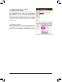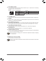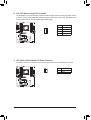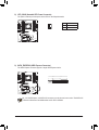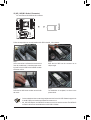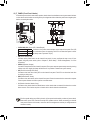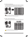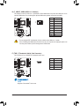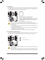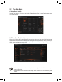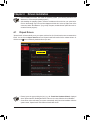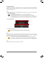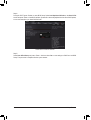
1
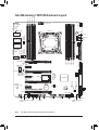
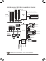
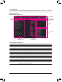
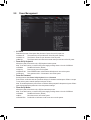
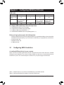
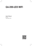
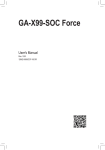
GA-X99-Gaming 7 WIFI User's Manual Rev. 1001 12ME-X99G7WF-1001R Motherboard GA-X99-Gaming 7 WIFI Motherboard GA-X99-Gaming 7 WIFI Aug. 15, 2014 Aug. 15, 2014 Wireless Module Country Approvals: See the latest safety and regulatory documents at GIGABYTE's website. Copyright © 2014 GIGA-BYTE TECHNOLOGY CO., LTD. All rights reserved. The trademarks mentioned in this manual are legally registered to their respective owners. Disclaimer Information in this manual is protected by copyright laws and is the property of GIGABYTE. Changes to the specifications and features in this manual may be made by GIGABYTE without prior notice. No part of this manual may be reproduced, copied, translated, transmitted, or published in any form or by any means without GIGABYTE's prior written permission. Documentation Classifications In order to assist in the use of this product, GIGABYTE provides the following types of documentations: For quick set-up of the product, read the Quick Installation Guide included with the product. For detailed product information, carefully read the User's Manual. For product-related information, check on our website at: http://www.gigabyte.com Identifying Your Motherboard Revision The revision number on your motherboard looks like this: "REV: X.X." For example, "REV: 1.0" means the revision of the motherboard is 1.0. Check your motherboard revision before updating motherboard BIOS, drivers, or when looking for technical information. Example: Table of Contents Box Contents....................................................................................................................6 Optional Items..................................................................................................................6 GA-X99-Gaming 7 WIFI Motherboard Layout.................................................................7 GA-X99-Gaming 7 WIFI Motherboard Block Diagram.....................................................8 Chapter 1 Hardware Installation......................................................................................9 1-1 1-2 1-3 Installation Precautions.................................................................................... 9 Product Specifications.................................................................................... 10 Installing the CPU and CPU Cooler............................................................... 13 1-3-1 Installing the CPU...................................................................................................13 1-3-2 Installing the CPU Cooler.......................................................................................15 1-4 Installing the Memory..................................................................................... 16 1-4-1 4 Channel Memory Configuration..........................................................................16 1-4-2 Installing a Memory.................................................................................................17 1-5 1-6 1-7 1-8 1-9 1-10 1-11 Installing an Expansion Card.......................................................................... 18 Setting up AMD CrossFire™/NVIDIA® SLI™ Configuration.............................. 19 Back Panel Connectors.................................................................................. 21 Installing the I/O Shield................................................................................... 23 Onboard Buttons, Switches, and LEDs.......................................................... 24 Changing the Operational Amplifier............................................................... 26 Internal Connectors........................................................................................ 27 Chapter 2 BIOS Setup...................................................................................................39 2-1 Startup Screen................................................................................................ 40 2-2 The Main Menu............................................................................................... 41 2-3M.I.T................................................................................................................ 44 2-4 System Information......................................................................................... 56 2-5 BIOS Features................................................................................................ 57 2-6Peripherals...................................................................................................... 60 2-7Chipset............................................................................................................ 62 2-8 Power Management........................................................................................ 65 2-9 Save & Exit..................................................................................................... 67 Chapter 3 Configuring SATA Hard Drive(s)...................................................................69 3-1 3-2 Configuring SATA Controllers......................................................................... 69 Installing the SATA RAID/AHCI Driver and Operating System...................... 81 -4- Chapter 4 Drivers Installation........................................................................................85 4-1 Chipset Drivers............................................................................................... 85 4-2 Application Software....................................................................................... 86 4-3Information...................................................................................................... 86 Chapter 5 Unique Features...........................................................................................87 5-1 BIOS Update Utilities...................................................................................... 87 5-1-1 5-1-2 5-1-3 5-2 Updating the BIOS with the Q-Flash Utility............................................................87 Updating the BIOS with the @BIOS Utility............................................................ 90 Using Q-Flash Plus.................................................................................................91 APP Center..................................................................................................... 92 5-2-1EasyTune.................................................................................................................93 5-2-2 System Information Viewer.................................................................................... 94 5-2-3 EZ Setup................................................................................................................ 95 5-2-4 Fast Boot................................................................................................................ 98 5-2-5 Smart TimeLock..................................................................................................... 99 5-2-6 Smart Recovery 2................................................................................................ 100 5-2-7 USB Blocker..........................................................................................................102 5-2-8 Ambient LED.........................................................................................................103 5-2-9V-Tuner..................................................................................................................104 5-2-10 Smart Switch.........................................................................................................105 5-2-11 Cloud Station Server........................................................................................... 106 5-2-12 Game Controller....................................................................................................112 Chapter 6 Appendix..................................................................................................... 113 6-1Qualcomm® Atheros Killer Network Manager...............................................113 6-2 Configuring Audio Input and Output..............................................................114 6-2-1 6-2-2 6-2-3 6-2-4 6-2-5 Configuring 2/5.1-Channel Audio.........................................................................114 Creative Software Suite........................................................................................114 Configuring S/PDIF Out........................................................................................118 Configuring Audio Recording...............................................................................119 Using the Sound Recorder...................................................................................121 6-3Troubleshooting............................................................................................ 122 6-3-1 Frequently Asked Questions ...............................................................................122 6-3-2 Troubleshooting Procedure..................................................................................123 6-4 Debug LED Codes........................................................................................ 125 Regulatory Statements............................................................................................ 129 Contact Us............................................................................................................... 135 -5- Box Contents 55 55 55 55 55 55 55 55 55 55 55 55 55 GA-X99-Gaming 7 WIFI motherboard Motherboard driver disk Wireless module driver disk User's Manual Quick Installation Guide Six SATA cables One 1 to 3 power cable (2x4 ATX 12V) I/O Shield One 2-Way SLI bridge connector Two 3-Way SLI bridge connectors (GC-3SLI-X99 and GC-3SLI) One 4-Way SLI bridge connector One 2-Way CrossFire bridge connector One antenna The box contents above are for reference only and the actual items shall depend on the product package you obtain. The box contents are subject to change without notice. Optional Items 2-port USB 2.0 bracket (Part No. 12CR1-1UB030-6*R) eSATA bracket (Part No. 12CF1-3SATPW-4*R) 3.5" Front Panel with 2 USB 3.0/2.0 ports (Part No. 12CR1-FPX582-2*R) -6- DDR4_4_2B DDR4_3_1B KB_MS_USB DDR4_2_2A DDR4_1_1A GA-X99-Gaming 7 WIFI Motherboard Layout ATX_12V_2X4 CPU_FAN HS LGA2011-3 Renesas® uPD720210 DTB CMOS_SW CPU_OPT ATX LED_CON1 Renesas® uPD720210 USB30_LAN1 ATX4P DDR4_5_1C DDR4_6_2C PCIE_1 TI Burr Brown® PCIE_5 OPA2134 DDR4_7_1D Intel® GbE LAN DDR4_8_2D ANTENNA_BRACKET LED_CON2 BAT GA-X99-Gaming 7 WIFI iTE® Super I/O PCIE_3 F_AUDIO F_USB1 SYS_FAN1 SYS_FAN2 System Temperature THB_C F_USB2 Sensor 2 CLR_CMOS F_USB30_2 (Note) For debug code information, please refer to Chapter 6. -7- F_USB30_1 F_PANEL sSATA3 3 1 2 0 B_BIOS PCIE_7 BBIOS_LED Creative® Sound Core 3D SATA_EXPRESS 3 2 1 SATA3 5 4 0 Intel® X99 PCIE_2 M_BIOS Wi-Fi Module M2_10G Qualcomm® Atheros Killer PCIE_6 E2201 LAN M2_WIFI PCIE_4 CAP_SW MBIOS_LED AUDIO RST_SW Debug LED (Note) USB30_LAN2 BIOS_SW PW_SW SB FBIOS_LED R_USB30 SYS_FAN3 System Temperature Sensor 1 GA-X99-Gaming 7 WIFI Motherboard Block Diagram 2 PCI Express x8 1 PCI Express x16 1 PCI 1 PCI Express x16 Express x8 CPU CLK+/- (100 MHz) or PCIe CLK (100 MHz) LGA2011-3 CPU x16 x16 Switch x8 4 Channel Memory DMI 2.0 x16 DDR4 2133/1866/1600/1333 MHz PCI Express Bus Dual BIOS x1 PCI Express Bus PCIe CLK (100 MHz) x1 x1 x1 x1 Qualcomm Atheros Killer E2201 LAN ® RJ45 LAN1 2 SATA 6Gb/s 4 SATA 6Gb/s M.2 Wi-Fi x1 SATA Express or 3 PCI Express x1 Wi-Fi Module M.2 or Switch Intel® X99 4 SATA 6Gb/s Renesas uPD720210 Hub 4 USB 3.0/2.0 Renesas uPD720210 Hub 4 USB 3.0/2.0 ® ® Intel GbE LAN ® 4 USB 3.0/2.0 RJ45 6 USB 2.0/1.1 LAN2 LPC iTE® Bus Super I/O PS/2 KB/Mouse S/PDIF Out Line Out MIC/Line In Rear Speaker Out Center/Subwoofer Speaker Out Headphone/Speaker Out Creative® Sound Core 3D For detailed product information/limitation(s), refer to "1-2 Product Specifications." -8- Chapter 1 Hardware Installation 1-1 Installation Precautions The motherboard contains numerous delicate electronic circuits and components which can become damaged as a result of electrostatic discharge (ESD). Prior to installation, carefully read the user's manual and follow these procedures: •• Prior to installation, make sure the chassis is suitable for the motherboard. •• Prior to installation, do not remove or break motherboard S/N (Serial Number) sticker or warranty sticker provided by your dealer. These stickers are required for warranty validation. •• Always remove the AC power by unplugging the power cord from the power outlet before installing or removing the motherboard or other hardware components. •• When connecting hardware components to the internal connectors on the motherboard, make sure they are connected tightly and securely. •• When handling the motherboard, avoid touching any metal leads or connectors. •• It is best to wear an electrostatic discharge (ESD) wrist strap when handling electronic components such as a motherboard, CPU or memory. If you do not have an ESD wrist strap, keep your hands dry and first touch a metal object to eliminate static electricity. •• Prior to installing the motherboard, please have it on top of an antistatic pad or within an electrostatic shielding container. •• Before unplugging the power supply cable from the motherboard, make sure the power supply has been turned off. •• Before turning on the power, make sure the power supply voltage has been set according to the local voltage standard. •• Before using the product, please verify that all cables and power connectors of your hardware components are connected. •• To prevent damage to the motherboard, do not allow screws to come in contact with the motherboard circuit or its components. •• Make sure there are no leftover screws or metal components placed on the motherboard or within the computer casing. •• Do not place the computer system on an uneven surface. •• Do not place the computer system in a high-temperature environment. •• Turning on the computer power during the installation process can lead to damage to system components as well as physical harm to the user. •• If you are uncertain about any installation steps or have a problem related to the use of the product, please consult a certified computer technician. -9- Hardware Installation 1-2 Product Specifications CPU Support for Intel® Core™ i7 processors in the LGA2011-3 package (Go to GIGABYTE's website for the latest CPU support list.) L3 cache varies with CPU Chipset Intel® X99 Express Chipset Memory 8 x DDR4 DIMM sockets supporting up to 64 GB of system memory Audio LAN Wireless Communication Module * Due to a Windows 32-bit operating system limitation, when more than 4 GB of physical memory is installed, the actual memory size displayed will be less than the size of the physical memory installed. 4 channel memory architecture Support for DDR4 2133/1866/1600/1333 MHz memory modules Support for non-ECC memory modules Support for Extreme Memory Profile (XMP) memory modules Support for RDIMM 1Rx8 memory modules (operate in non-ECC mode) (Go to GIGABYTE's website for the latest supported memory speeds and memory modules.) Creative® Sound Core 3D chip Support for Sound Blaster Recon3Di TI Burr Brown® OPA2134 operational amplifier High Definition Audio 2/5.1-channel Support for S/PDIF Out 1 x Qualcomm® Atheros Killer E2201 chip (10/100/1000 Mbit) (LAN1) 1 x Intel® GbE LAN phy (10/100/1000 Mbit) (LAN2) Wi-Fi 802.11 a/b/g/n/ac, supporting 2.4/5 GHz Dual-Band Bluetooth 4.0, 3.0+HS, 2.1+EDR Support for 11ac wireless standard and up to 867 Mbps data rate * Actual data rate may vary depending on environment and equipment. Expansion Slots 2 x PCI Express x16 slots, running at x16 (PCIE_1, PCIE_2) * For optimum performance, if only one PCI Express graphics card is to be installed, be sure to install it in the PCIE_1 slot; if you are installing two PCI Express graphics cards, it is recommended that you install them in the PCIE_1 and PCIE_2 slots. 2 x PCI Express x16 slots, running at x8 (PCIE_3, PCIE_4) * The PCIE_4 slot shares bandwidth with the PCIE_1 slot. When the PCIE_4 slot is populated, the PCIE_1 slot will operate at up to x8 mode. * When an i7-5820K CPU is installed, the PCIE_2 slot operates at up to x8 mode and the PCIE_3 operates at up to x4 mode. Multi-Graphics Technology (All PCI Express x16 slots conform to PCI Express 3.0 standard.) 3 x PCI Express x1 slots (The PCI Express x1 slots conform to PCI Express 2.0 standard.) 1 x M.2 Socket 1 connector for the wireless communication module (M2_WIFI) Support for 4-Way/3-Way/2-Way AMD CrossFire™/NVIDIA® SLI™ technology * The 4-Way NVIDIA® SLI™ configuration is not supported when an i7-5820K CPU is installed. To set up a 3-Way SLI configuration, refer to "1-6 Setting up AMD CrossFire™/ NVIDIA® SLI™ Configuration." Storage Interface Chipset: - 1 x M.2 Socket 3 connector (M2_10G) - 1 x SATA Express connector - 6 x SATA 6Gb/s connectors (SATA3 0~5) Hardware Installation - 10 - Storage Interface - USB Internal Connectors Back Panel Connectors Support for RAID 0, RAID 1, RAID 5, and RAID 10 * Only AHCI mode is supported when an M.2 PCIe SSD or a SATA Express device is installed. (M2_10G, SATA Express, and SATA3 4/5 connectors can only be used one at a time. The SATA3 4/5 connectors will become unavailable when an M.2 SSD is installed in the M2_10G connector.) Chipset: - 4 x SATA 6Gb/s connectors (sSATA3 0~3), supporting IDE and AHCI modes only (An operating system installed on the SATA3 0~5 ports cannot be used on the sSATA3 0~3 ports.) Chipset: - 4 x USB 3.0/2.0 ports (available through the internal USB headers) - 6 x USB 2.0/1.1 ports (2 ports on the back panel, 4 ports available through the internal USB headers) Chipset + 2 Renesas® uPD720210 USB 3.0 Hubs: -8 x USB 3.0/2.0 ports on the back panel 1 x 24-pin ATX main power connector 1 x 8-pin ATX 12V power connector 1 x PCIe power connector 1 x I/O shield audio LED power connector 1 x heatsink LED power connector 1 x SATA Express connector 10 x SATA 6Gb/s connectors 1 x M.2 Socket 3 connector 1 x CPU fan header 1 x water cooling fan header (CPU_OPT) 3 x system fan headers 1 x front panel header 1 x front panel audio header 2 x USB 3.0/2.0 headers 2 x USB 2.0/1.1 headers 1 x Thunderbolt add-in card connector 1 x Clear CMOS jumper 1 x power button 1 x reset button 1 x Clear CMOS button 1 x Direct to BIOS button 1 x audio gain control switch Voltage Measurement Points 2 x BIOS switches 1 x PS/2 keyboard/mouse port 1 x CPU overclocking button 1 x Fast Boot button 1 x Clear CMOS button 8 x USB 3.0/2.0 ports 2 x USB 2.0/1.1 ports 2 x RJ-45 ports 1 x optical S/PDIF Out connector - 11 - Hardware Installation Back Panel Connectors 5 x audio jacks (Center/Subwoofer Speaker Out, Rear Speaker Out, Line In/Mic In, Line Out, Headphone) 2 x SMA antenna connectors (2T2R) I/O Controller iTE® I/O Controller Chip Hardware Monitor BIOS Unique Features Bundled Software Operating System Form Factor System voltage detection CPU/System/Chipset temperature detection CPU/CPU OPT/System fan speed detection CPU/System/Chipset overheating warning CPU/CPU OPT/System fan fail warning CPU/CPU OPT/System fan speed control * Whether the fan speed control function is supported will depend on the cooler you install. 2 x 128 Mbit flash Use of licensed AMI UEFI BIOS Support for DualBIOS™ Support for Q-Flash Plus PnP 1.0a, DMI 2.7, WfM 2.0, SM BIOS 2.7, ACPI 5.0 Support for APP Center * A vailable applications in APP Center may differ by motherboard model. Supported functions of each application may also differ depending on motherboard specifications. -@BIOS - Ambient LED -EasyTune - EZ Setup - Fast Boot - Game Controller - Cloud Station - ON/OFF Charge - Smart TimeLock - Smart Recovery 2 - System Information Viewer - USB Blocker -V-Tuner Support for Q-Flash Support for Smart Switch Support for Xpress Install Norton® Internet Security (OEM version) Intel® Smart Response Technology Support for Windows 8.1/8/7 E-ATX Form Factor; 30.5cm x 25.9cm * GIGABYTE reserves the right to make any changes to the product specifications and product-related information without prior notice. * Please visit the Support & Downloads\Utility page on GIGABYTE's website to check the supported operating system(s) for the software listed in the "Unique Features" and "Bundled Software" columns. Hardware Installation - 12 - 1-3 Installing the CPU and CPU Cooler Read the following guidelines before you begin to install the CPU: •• Make sure that the motherboard supports the CPU. (Go to GIGABYTE's website for the latest CPU support list.) •• Always turn off the computer and unplug the power cord from the power outlet before installing the CPU to prevent hardware damage. •• Locate the pin one of the CPU. The CPU cannot be inserted if oriented incorrectly. (Or you may locate the notches on both sides of the CPU and alignment keys on the CPU socket.) •• Apply an even and thin layer of thermal grease on the surface of the CPU. •• Do not turn on the computer if the CPU cooler is not installed, otherwise overheating and damage of the CPU may occur. •• Set the CPU host frequency in accordance with the CPU specifications. It is not recommended that the system bus frequency be set beyond hardware specifications since it does not meet the standard requirements for the peripherals. If you wish to set the frequency beyond the standard specifications, please do so according to your hardware specifications including the CPU, graphics card, memory, hard drive, etc. 1-3-1 Installing the CPU A. Locate the alignment keys on the motherboard CPU socket and the notches on the CPU. LGA2011-3 CPU Socket Alignment Key Alignment Key Pin One Corner of the CPU Socket Alignment Key Alignment Key LGA2011-3 CPU - 13 - Notch Notch Notch Notch Triangle Pin One Marking on the CPU Hardware Installation B. Follow the steps below to correctly install the CPU into the motherboard CPU socket. •• Before installing the CPU, make sure to turn off the computer and unplug the power cord from the power outlet to prevent damage to the CPU. •• To protect the socket contacts, do not remove the protective plastic cover unless the CPU is inserted into the CPU socket. Save the cover properly and replace it if the CPU is removed. Lever A Lever B Step 1: Push the lever closest to the "unlock" mark " " (below referred as lever A) down and away from the socket to release it. Step 2: Push the lever closest to the "lock" mark " " (below referred as lever B) down and away from the socket. Then lift the lever. Step 3: Gently press lever A to allow the load plate to rise. Open the load plate. Note: DO NOT touch the socket contacts after the load plate is opened. Step 4: Hold the CPU with your thumb and index fingers. Align the CPU pin one mark (triangle) with the triangle mark on metal socket frame and carefully insert the CPU into the socket vertically. Step 5: Once the CPU is properly inserted, carefully replace the load plate. Then secure lever B under its retention tab. Step 6: Finally, secure lever A under its retention tab to complete the installation of the CPU. Then carefully remove the plastic cover. Save it properly and always replace it when the CPU is not installed. Hardware Installation - 14 - 1-3-2 Installing the CPU Cooler Refer to the steps below to correctly install the CPU cooler on the motherboard. (Actual installation process may differ depending the CPU cooler to be used. Refer to the user's manual for your CPU cooler.) Step 1: Apply an even and thin layer of thermal grease on the surface of the installed CPU. Step 2: Place the cooler atop the CPU, aligning the four mounting screws with the mounting holes on the ILM. Step 3: Use one hand to hold the cooler and the other to tighten the screws in a diagonal sequence with a screw driver. Begin tightening a screw with a few turns and repeat with the screw diagonally opposite the one you just tightened. Then do the same to the other pair. Next, fully tighten the four screws. Step 4: Finally, attach the power connector of the CPU cooler to the CPU fan header (CPU_FAN) on the motherboard. Use extreme care when removing the CPU cooler because the thermal grease/tape between the CPU cooler and CPU may adhere to the CPU. Inadequately removing the CPU cooler may damage the CPU. - 15 - Hardware Installation 1-4 Installing the Memory Read the following guidelines before you begin to install the memory: •• Make sure that the motherboard supports the memory. It is recommended that memory of the same capacity, brand, speed, and chips be used. (Go to GIGABYTE's website for the latest supported memory speeds and memory modules.) •• Always turn off the computer and unplug the power cord from the power outlet before installing the memory to prevent hardware damage. •• Memory modules have a foolproof design. A memory module can be installed in only one direction. If you are unable to insert the memory, switch the direction. 1-4-1 4 Channel Memory Configuration DDR4_8_2D DDR4_7_1D DDR4_6_2C DDR4_5_1C DDR4_1_1A DDR4_2_2A DDR4_3_1B DDR4_4_2B This motherboard provides eight DDR4 memory sockets and supports 4 Channel Technology. After the memory is installed, the BIOS will automatically detect the specifications and capacity of the memory. The eight DDR4 memory sockets are divided into four channels and each channel has two memory sockets as following: Channel A: DDR4_1_1A, DDR4_2_2A Channel B: DDR4_3_1B, DDR4_4_2B Channel C: DDR4_5_1C, DDR4_6_2C Channel D: DDR4_7_1D, DDR4_8_2D Refer to the table below for memory installation according to the number of the memory modules you want to install: 1 Module 2 Modules 4 Modules 6 Modules 8 Modules DDR4_1_1A --l l l DDR4_2_2A ----l DDR4_3_1B l l l l l DDR4_4_2B ---l l DDR4_8_2D ---l l DDR4_7_1D -l l l l DDR4_6_2C ----l DDR4_5_1C --l l l Note 1: When installing the memory, make sure to begin with the first socket of each channel, such as DDR4_1_1A, DDR4_3_1B, DDR4_5_1C, and DDR4_7_1D. Note 2: If you are using a RDIMM memory, make sure it is a 1Rx8 one. Note 3: To ensure memory compatibility, we do not recommend that you install RDIMM and UDIMM memory at the same time. Hardware Installation - 16 - 1-4-2 Installing a Memory Before installing a memory module, make sure to turn off the computer and unplug the power cord from the power outlet to prevent damage to the memory module. DDR4 and DDR3 DIMMs are not compatible to each other or DDR2 DIMMs. Be sure to install DDR4 DIMMs on this motherboard. Notch DDR4 DIMM A DDR4 memory module has a notch, so it can only fit in one direction. Follow the steps below to correctly install your memory modules in the memory sockets. Step 1: Note the orientation of the memory module. Spread the retaining clip at the right end of the memory socket. Place the memory module on the socket. As indicated in the picture on the left, place your fingers on the top edge of the memory, push down on the memory and insert it vertically into the memory socket. Step 2: The clip at the right end of the socket will snap into place when the memory module is securely inserted. - 17 - Hardware Installation 1-5 Installing an Expansion Card Read the following guidelines before you begin to install an expansion card: •• Make sure the motherboard supports the expansion card. Carefully read the manual that came with your expansion card. •• Always turn off the computer and unplug the power cord from the power outlet before installing an expansion card to prevent hardware damage. PCI Express x16 Slot PCI Express x1 Slot Follow the steps below to correctly install your expansion card in the expansion slot. 1. Locate an expansion slot that supports your card. Remove the metal slot cover from the chassis back panel. 2. Align the card with the slot, and press down on the card until it is fully seated in the slot. 3. Make sure the metal contacts on the card are completely inserted into the slot. 4. Secure the card's metal bracket to the chassis back panel with a screw. 5. After installing all expansion cards, replace the chassis cover(s). 6. Turn on your computer. If necessary, go to BIOS Setup to make any required BIOS changes for your expansion card(s). 7. Install the driver provided with the expansion card in your operating system. Example: Installing and Removing a PCI Express Graphics Card: •• Installing a Graphics Card: Gently push down on the top edge of the card until it is fully inserted into the PCI Express slot. Make sure the card is securely seated in the slot and does not rock. •• Removing the Card: Gently push back on the lever on the slot and then lift the card straight out from the slot. Hardware Installation - 18 - 1-6 Setting up AMD CrossFire™/NVIDIA® SLI™ Configuration A. System Requirements -- Windows 8.1/8/7 operating system -- A CrossFire/SLI-supported motherboard with two or more PCI Express x16 slots and correct driver -- CrossFire/SLI-ready graphics cards of identical brand and chip and correct driver (Current GPUs that support 3-Way/4-Way CrossFire technology include the ATI Radeon™ HD 3800, HD 4800, HD 5800 series, and AMDRadeon™ HD 6800, HD 6900, HD 7800, and HD 7900 series. Current GPUs that support 3-Way/4-Way SLI™ technology include the NVIDIA 8800 GTX, 8800 Ultra, 9800 GTX, GTX 260, GTX 280, GTX 470, GTX 480, GTX 570, GTX 580, GTX 590, and GTX 600 series.) For the latest GPU support information, please refer to the AMD/NVIDIA® website.) (Note 1) -- CrossFire (Note 2)/SLI bridge connectors -- A power supply with sufficient power is recommended (Refer to the manual of your graphics cards for the power requirement) B. Connecting the Graphics Cards Step 1: Observe the steps in "1-5 Installing an Expansion Card" and install CrossFire/ SLI graphics cards on the PCI Express x16 slots. Step 2: Insert the CrossFire (Note 2)/SLI bridge connectors in the CrossFire/SLI gold edge connectors on top of the cards. Step 3: Plug the display cable into the graphics card on the PCIE_1 slot. Refer to the table below when an i7-5960X or i7-5930K CPU is installed: PCIE_1 PCIE_4 PCIE_2 PCIE_3 1 Graphics Card l ---- 2 Graphics Cards l -l -- 3 Graphics Cards l -l l 4 Graphics Cards l l l l PCIE_1 PCIE_4 PCIE_2 PCIE_3 To set up a 3-Way SLI configuration, use the GC-3SLI-X99 bridge connector. Refer to the table below for setting up a 3-Way SLI configuration with an i7-5820K CPU. Make sure to use the GC-3SLI bridge connector. PCIE_1 PCIE_4 PCIE_2 PCIE_3 1 Graphics Card l ---- 2 Graphics Cards l -l -- 3 Graphics Cards l l l -- (Note 1) The 4-Way SLI configuration is not supported when an i7-5820K CPU is installed. (Note 2) The bridge connector(s) may be needed or not depending on your graphics cards. •• P rocedure and driver screen for enabling CrossFire/SLI technology may differ by graphics cards and driver version. Refer to the manual that came with your graphics cards for more information about enabling CrossFire/ SLI technology. •• When two or more graphics cards are installed, we recommend that you connect the SATA power cable from the power supply to the ATX4P connector to ensure system stability. - 19 - Hardware Installation C. Configuring the Graphics Card Driver C-1. To Enable CrossFire Function After installing the graphics card driver in the operating system, go to the AMD Catalyst Control Center. Browse to Performance\ AMD CrossFireX™ and ensure the Enable AMD CrossFireX check box is selected. If your system has more than two CrossFire cards, select the GPU combination you want