1
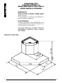
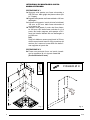
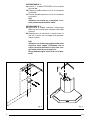
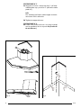
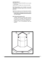
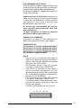
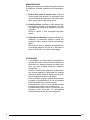
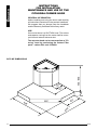
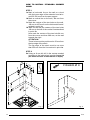
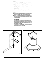
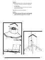
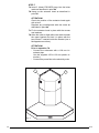
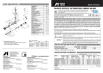
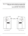
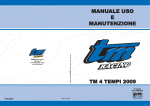
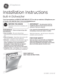
Cappa Angolo / Corner Hood
PITAGORA
2439.001
Cappe d'arredo / HOODS
Forni / Built-in ovens
Lavelli / Sinks
Miscelatori / Faucets
Piani Cottura / Cooker hobs
I taliano
ISTRUZIONI PER
L’INSTALLAZIONE, LA
MANUTENZIONE E L’USO DELLA
CAPPA ANGOLO PITAGORA
GENERALITA':
Prima di installare e utilizzare la cappa, leggere
attentamente tutte le istruzioni riportate nel seguente manuale.
Si raccomanda di conservare accuratamente libretto e certificato di garanzia.
UTILIZZAZIONE:
La cappa appartiene al tipo ASPIRANTE; odori
e vapori aspirati devono essere convogliati in un
condotto esterno di evacuazione.
E’ possibile trasformare la cappa in “Filtrante”
acquistando la confezione - Filtro in carbone
cod. 9700409.
450 - 850
DIMENSIONI DI MASSIMA
0
22
0
90
42
1
2
3
4
0
40
*
89
8
8
89
3
F15
ISTRUZIONI DI MONTAGGIO CAPPA
ANGOLO PITAGORA
OPERAZIONE N° 1
1aSegnare sulla parete una linea orizzontale a
650-700 mm. dalle griglie dei piano cottura (filo
inf. Cappa).
1b Segnare sulla parete una linea verticale a 184 mm
dall'angolo.
1c Indicare sulla parete i centri dei due fori distanti
100 mm. a 455 mm. dalla linea orizzontale di
cui al punto 1a.
1d Indicare sulla parete il centro del foro distante 180 mm a SX della linea verticale di cui al
punto 1b. Inoltre segnare sulla parete a DX i
centri dei duefori distanti 84 mm dall’angolo e
poi 280 mm.
N.B.
Detti fori debbono essere posizionati a 50 mm
dal filo superiore del camino.Il filo superiore del
camino puo’ essere al maxa 950 mm dalla linea segnata nel punto 1a.
OPERAZIONE N°2
2a Forare con punta da 8 mm. nei centri ricavaticon le operazioni di cui al punto 1c ed 1d
(Profondità min.60 mm.)
0
18
84
28
FISHER Ø 8
50
50
0
mm
0
455
4
18
650-700
max 940
10
Fig. 1
4
Fig. 2
F15
OPERAZIONE N° 3
3ainserire n° 5 tasselli FISCHER nei fori ricavati
al punto 2a.
3bFissare la staffa inferiore con le viti inserendo
le rondelle
3c Fissare la staffa superiore con le viti inserendo
le rondelle
N.B.
utilizzare una livella per controllare il corretto posizionamento delle staffe.
OPERAZIONE N° 4
4aAppendere la cappa mediante l’inserimento
delle due viti X nelle asole ricavate sulla staffa
inferiore
4bRegolare con un cacciavite “a punta croce” le
due viti in modo che la cappa risulti perfettamente in piano
N.B.
utilizzare una livella appoggiata nella parte
superiore della cappa. Controllare che la
cappa risulti posizionata in linea con il segno sulla parete di cui al punto 1a.
Eventualmente agire sulle viti di cui al punto 4b.
±
5
X
Fig. 3
5
Fig. 4
F15
ITALIANO
OPERAZIONE N° 5
5aSegnare sul muro il centro dei foro Y (all’internodella parte sup.) e dei fori Z (all’interno della
parte inf.).
N.B.
Per accedere all’interno della cappa occorrerimunovere i filtri in alluminio.
5b Togliere la cappa dal muro
OPERAZIONE N° 6
6aForare con punta da 8 mm. nei centri ricavati
con le operazioni di cui al punto 5a (Profondità min.60 mm.)
Y
Fig. 5
6
Z
Fig. 6
F15
OPERAZIONE N° 7
7aInserire n° 3 tasselli FISCHER nei fori ricavati
al punto 6a.
7b Appendere la cappa come da operazione 4a.
N.B. Ricontrollare con la livella il suo posizionamento altrimenti agire sulle viti come al
punto 4a.
7c Fissare la cappa con le viti inserendo le rondelle.
7d Far scorrere il tubo interno del camino verso la
staffa superiore e bloccarlo con le due viti (T)
inserite nella staffa stessa (utilizzare cacciavite
con testa a taglio).
N.B. Prima dell’operazione 7d:
- Collegare l’aspiratore mediante tubo di scarico
da 120 mm int. (utilizzare l’apposita riduzione
in plastica da 150 a 120 mm in dotazione) oppure con tubo da 150 mm (senza riduzione).
- Collegare il cavo di alimentazione alla rete
elettrica.
T
T
Fig. 7
7
F15
COLLEGAMENTO ELETTRICO:
Prima di effettuare qualsiasi collegamento assicurarsi che la tensione di rete corrisponda a quella riportata sull’etichetta posta all’interno dell’apparecchio.
Si consiglia di affidare il collegamento elettrico ad
un tecnico qualificato.
Apparecchio sprovvisto di spina: applicare una
spina a norme oppure un interruttore omnipolare
a norme con una distanza dei contatti in apertura
non inferiore a 3 mm. Il cavo di terra non deve
essere interrotto dall’interruttore.
Si declina ogni responsabilità per inconvenienti derivanti dall’inosservanza delle suddette disposizioni.
La ditta costruttrice si riserva di apportare
qualsiasi modifica senza preavviso.
PANNELLO DI COMANDO:
Il pannello di comando è di tipo elettronico ed è
posizionato nella parte anteriore della cappa.
FUNZIONE TASTI:
P1 Accensione 1a velocità e spegnimento motore
P2 Accensione 2a velocità e spegnimento motore
P3 Accensione 3a velocità e spegnimento motore
P4Accensione 4a velocità e spegnimento motore
P5Accensione e spegnimento luci
NOTE:
- Dopo 40 ore di funzionamento della cappa, a
motore e luci spenti, lampeggia il led corrispondente al tasto luce per segnalare la necessità
della pulizia dei Filtri ACCIAIO.
N.B. Premendo “a lungo” il tasto “P5”, a motore
e luci spenti, l’allarme viene RESETTATO.
- Dopo 120 ore di fuzionamento della cappa, a
morote e luci spenti, lampeggiano il led corrispondente al tasto luce ed il led corrispondente
alla 1a velocità per segnalare la necessità della pulizia dei Filtri CARBONE.
N.B. Premendo “a lungo” il tasto “P5”, a motore
e luci spenti, l’allarme viene RESETTATO.
- E’ possibile ritardare, automaticamente, lo spegnimento del motore premendo a lungo uno
dei tasti delle Velocità.
Il motore rimarrà acceso per altri 15 minuti.
P1
8
P2
P3
P4 P5
F15
MANUTENZIONE:
Scollegare l’apparecchio dalla rete elettrica prima
di effettuare qualsiasi operazione di manutenzione.
1) Pulizia delle parti di acciaio inox: al fine di
evitare graffi sulle superfici si sconsiglia l’uso
di polveri abrasive o spazzole. Utilizzare detergenti liquidi specifici per acciaio inox.
2) Pulizia del filtro: smontare il filtro agendo sulla maniglia e lavarlo in lavastoviglie o con acqua saponata, evitando di strofinare con panni
o spugne.
Prima di riporre il filtro asciugarlo accuratamente.
3) Sostituzione lampada: togliere la tensione e,
mediante un cacciavite, togliere l’anello che
supporta il vetro, avendo cura di non danneggiarlo.
Rimuovere il vetro e sostituire la lampada con
un’analoga (alogena 12V-20 W ). Rimontare il
vetro di protezione e l’anello di bloccaggio.
ATTENZIONE
- L’aria espulsa non deve essere convogliata in
condotti che siano condivisi da altri apparecchi
alimentati con energia diversa da quella elettrica. (es. stufe a legna, stufa gas, caldaie a
combustibili ...)
- Qualora l’utilizzo della cappa sia contemporaneo ad altri apparecchi, alimentati con energia
diversa da quella elettrica, dovrà essere prevista un’adeguata aerazione del locale.
- E’ da escludere l’impiego di fiamma libera sotto
la cappa o la preparazione di cibi alla fiamma
poichè potrebbe dar luogo ad incendi.
Controllare che l’olio non si surriscaldi durante
le fritture onde evitare che prenda fuoco.
- L’inosservanza delle norme di pulizia dei filtri
comporta rischi d’incendio. Si raccomanda
quindi di attenersi alle istruzioni suggerite.
9
F15
IMPORTANTE:
il montaggio della cappa in presenza di altri apparecchi non elettrici (es. stufe a legna, stufa gas,
caldaie a combustibili ...) dovrà prevedere uno
scarico esterno che assicuri una buona aerazione. Verificare le condizioni del camino di scarico
nel caso in cui quest’ultimo sia rimasto inutilizzato
per molto tempo.
Ricordarsi inoltre di prestare la massima attenzione alle locali norme vigenti in materia di evacuazione fumi.
Tutti i suggerimenti forniti al riguardo devono essere scrupolosamente osservati al fine di evitare
spiacevoli inconvenienti.
IL COSTRUTTORE DECLINA OGNI RESPONSABILITA' DERIVANTE DAL MANCATO RISPETTO
DELLE INDICAZIONI FORNITE.
10 F15
E nglish
INSTRUCTIONS
FOR INSTALLATION,
MAINTENANCE AND USE OF THE
PITAGORA CORNER HOOD
GENERAL INFORMATION:
before installing and using the hood, read carefully
all instructions contained in the present handbook.
We suggest that you always keep the handbook
and the warranty certificate within easy reach.
USE:
the hood at issue is a SUCTION hood. The odours
and vapours coming from the motor shall be conveyed into and external exhaust duct.
The extractor hood can be converted into a “Filtering” hood by purchasing the Carbon Filter
pack – carbon filter cod. 9700409.
450 - 850
OUTLINE DIMENSIONS
0
22
0
90
42
1
2
3
4
0
40
*
89
8
8
89
11 F15
HOW TO INSTALL PITAGORA CORNER
HOOD
STEP 1
1aMark a horizontal line on the wall on a level
with the lower edge of the extractor hood at least 650-700 mm from the pan support.
1b Mark a vertical line on the wall, 184 mm from
the corner..
1c Mark the centres of the two holes on the wall,
100 mm to 455 mm from the Horizontal line described in point 1a.
1d Mark on the wall the centers of the two holes
180 mm to the left of the vertical line described
in point 1b.
Now mark the centers of the two hole 84 mm
from the corner and then 280 mm, on the wall
towards the right.
ATTENTION:
These holes must be positioned to 50 mm from
the top edge of the stack.
The top edge of the stack must be no more
than 950 mm from the line marked in point 1a.
STEP 2
2aUsing an 8 mm bit, drill in the centres marked
according to the instructions in points 1c and 1d
(the holes must be at least 60 mm in depth)
0
18
84
28
FISHER Ø 8
50
50
0
mm
0
455
4
18
650-700
max 940
10
Fig. 1
12 Fig. 2
F15
STEP 3
3aInsert 5 (five) FISCHER plugs into the holes
made as described in point 2a.
3b Fix the lower bracket in place with the screws,
not forgetting to insert the washers.
3c Fix the upper bracket in place with the screws.
ATTENTION!
Use a level to make sure that the brackets
have been correctly positioned.
STEP 4
4aHang up the extractor hood by inserting the two
screws X into the slots in the lower bracket.
4b Using a screwdriver with a cross-headed tip,
adjust the two screws so that the extractor hood
is perfectly level
ATTENTION!
Place the level on top part of the extractor hood.
Make sure that the extractor hood is positioned
on a level with the mark made on the wall as
described in point 1a.
If necessary, regulate the position with the
screws described in point 4b.
±
5
X
Fig. 3
13 Fig. 4
F15
ITALIANO
STEP 5
5aMark the centre of hole Y (inside the upper part)
and holes Z (inside the lower part) on the wall.
ATTENTION!
To access the interior part of the hood, removede the alluminium filter.
5bRemove the hood from the wall.
STEP 6
6aUsing an 8 mm bit, drill in the centres formed
with the operations described in point 5a (the
holes must be at least 60 mm in depth)
Y
Fig. 5
14 Z
Fig. 6
F15
STEP 7
7aInsert 3 (three) FISCHER plugs into the holes
made as described in point 6a.
7b Hang up the extractor hood as described in
point 4a.
ATTENTION!
Check the position of the extractor hood again
with a level.
Regulate any misalignment with the screw as
described in point 4a.
7cFix the extractor hood in place with the screws
and washers.
7d Allow the tube to slight within the stack towards
the upper bracket and lock it in place with the
two screws T inserted inside the bracket (use a
flat-tipped screw driver)
ATTENTION!
Prior to operation 7d:
- Connect the exhauster with a 120 mm int.
exhaust pipe.
Use the supplied 150 to 120 mm plastic reduction.)
- Connect the power flex to the electricity main.
T
T
Fig. 7
15 F15
ELECTRICAL CONNECTIONS:
before carrying out any electrical connection, make
sure that the voltage corresponds to the one mentioned on the label located on the inside of the appliance. It is advisable to entrust the installation of
the electrical connection to a qualified technician.
Appliance provided without plug: please connect a plug or an omni-polar switch in compliance
to the existing local regulations, and with an opening connection distance not inferior to 3 mm, The
earth wire must not be interrupted by the switch.
Foster decline any responsibility for any inconveniences deriving from the non-observance of the aforesaid instructions of the use
of materials which are not in compliance with
the existing regulations.
CONTROL PANEL:
The control panel is electronic and is positioned in
the lower-end part of the hood.
FUNCTION OF BUTTONS:
1) TURN-ON 1st SPEED AND MOTOR TURN-OFF
2) TURN-ON 2nd SPEED AND MOTOR TURN-OFF
3) TURN-ON 3rd SPEED AND MOTOR TURN-OFF
4) TURN-ON 4th SPEED AND MOTOR TURN-OFF
5) Light ON/OFF button
REMARKS:
- After 40 hours use of the hood, at motor and
light switched off, indicator of key 5 flash to signal the need to clean st. steel filters.
ATTENTION!
Press for long time key n° 5, at motor and light
switched off: the alarm is reset.
- After 120 hours use of the hood, at motor and
light switched off, indicator of key 5 and 1 flash
to signal the need to clean carbon filters.
Press for long time key n° 5, at motor and light
switched off: the alarm is reset.
- It is possible to automatically delay the stalling
of the engine by pressing for long one of the
speed keys.
The engine will run for 15 minutes.
P1
16 P2
P3
P4 P5
F15
MAINTENANCE:
Please switch-off the electrical power, or disconnect the appliance before carrying out any maintenance operation.
1) Cleaning of the stainless steel parts: in order
to avoid scratches in the steel surfaces, please
don’t use abrasive powders or brushes. Use liquid detergents specifically made for stainless
steel items.
2) Filter Cleaning: Remove the filter from the
container and wash it in the dishwasher or with
soapy water, without rubbing it with a cloth or
a sponge.
Before replacing the filter, carefully dry it without deforming it.
3) Led replacement: switch-off the electrical
power, or disconnect the appliance, and by
means of a screwdriver, raise the ring which
sustains the glass, taking care not to damage
it. Remove the glass and replace the light bulb
with a similar one (halogen lamp 12V–20 W).
Re-assembly the safety glass and the sustaining ring (refer to the sketch:
ATTENTION:
- The expelled air must not be convoyed in ducts
which are shared by other appliances powered
with energy different from the electrical one.
- Should the use of the hood be contemporaneous to other appliances powered by energy
different from the electrical one, an adequate
ventilation on the room is to be foreseen.
- The use of an open flame under the hood or
the preparation of food with an open flame is to
be excluded, as this could cause a fire. Check
that the oil doesn’t overheat during the frying
process in order to prevent it from catching fire.
- The non-compliance to filter cleaning recommendations, causes a risk of fire. It is of course
recommended to follow the said instructions
17 F15
IMPORTANT:
The use of the hood in presence of other nonelectrical appliances (such as, but not limited to,
wood-burning stoves, gas stoves, non-electrical
water-heaters) requires the presence of an external exhaust which ensures a good ventilation of the
room.
Verify the conditions of the exhaust chimney in case
the hood is not used for a long period of time.
Please also pay the maximum attention to the local
standard regulations concerning exhaust scavenging.
All recommendations on the subject should be
scrupulously observed in order to avoid unpleasant
inconveniences.
THE MANUFACTURER DECLINES ANY RESPONSIBILITY CAUSED BY NON-COMPLIANCE TO THE HERE ABOVE MENTIONED RECOMMENDATIONS.
18 F15
19 F15
Grafica e Stampa: SERIART - www.seriart.com
F15 (05-10)
via M.S. Ottone, 18/20 - Brescello (RE)
ASSISTENZA TECNICA Tel. 0522/684450 - FAX 686019 MAIL [email protected]
MAGAZZINO RICAMBI Tel. / FAX 0522/684300 MAIL [email protected]