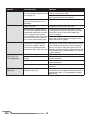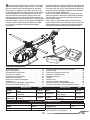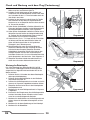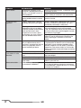
1
BO-105 CB 130 X
under license of Red Bull GmbH Austria
Instruction Manual
Bedienungsanleitung
Manuel d’utilisation
Manuale di Istruzioni
®
NOTICE
All instructions, warranties and other collateral documents are subject to change at the sole discretion of Horizon
Hobby, Inc. For up-to-date product literature, visit horizonhobby.com and click on the support tab for this product.
Meaning of Special Language
The following terms are used throughout the product literature to indicate various levels of potential harm when
operating this product:
NOTICE: Procedures, which if not properly followed, create a possibility of physical property damage AND a little or no
possibility of injury.
CAUTION: Procedures, which if not properly followed, create the probability of physical property damage AND
a possibility of serious injury.
WARNING: Procedures, which if not properly followed, create the probability of property damage, collateral damage,
and serious injury OR create a high probability of superficial injury.
WARNING: Read the ENTIRE instruction manual to become familiar with the features of the product before
operating. Failure to operate the product correctly can result in damage to the product, personal property and
cause serious injury.
This is a sophisticated hobby product. It must be operated with caution and common sense and requires some
basic mechanical ability. Failure to operate this Product in a safe and responsible manner could result in injury
or damage to the product or other property. This product is not intended for use by children without direct adult
supervision. Do not use with incompatible components or alter this product in any way outside of the instructions
provided by Horizon Hobby, Inc. This manual contains instructions for safety, operation and maintenance. It is essential to read and follow all the instructions and warnings in the manual, prior to assembly, setup or use, in order
to operate correctly and avoid damage or serious injury.
Age Recommendation: Not for children under 14 years. This is not a toy.
Safety Precautions and Guidelines
• Always keep a safe distance in all directions around
your model to avoid collisions or injury. This model is
controlled by a radio signal subject to interference from
many sources outside your control. Interference can
cause momentary loss of control.
• Always operate your model in open spaces away
from full-size vehicles, traffic and people.
• Always carefully follow the directions and warnings
for this and any optional support equipment
(chargers, rechargeable battery packs, etc.).
• Always keep all chemicals, small parts and anything
electrical out of the reach of children.
• Always avoid water exposure to all equipment not
specifically designed and protected for this purpose.
Moisture causes damage to electronics.
• Never place any portion of the model in your mouth
as it could cause serious injury or even death.
EN
• Never operate your model with low transmitter
batteries.
• Always keep aircraft in sight and under control.
• Always turn throttle hold on if the helicopter is out of
control or in danger of crashing.
• Always use fully charged batteries.
• Always keep transmitter powered on while aircraft is
powered.
• Always remove batteries before disassembly.
• Always keep moving parts clean.
• Always keep parts dry.
• Always let parts cool after use before touching.
• Always remove batteries after use.
• Never operate aircraft with damaged wiring.
• Never touch moving parts.
2
hey’re some of world’s greatest pilots and they fly their
machines to the limit every time they take to the sky.
They’re The Flying Bulls who operate more than 20 unique
historic aircraft for and on behalf of the RED BULL® EnergyDrink-Company. Their pilots are the only ones civil certified
to fly full aerobatic maneuvers with a civil helicopter, the BO105, and they’ve been thrilling millions at airshows around
the world since the late 1990s. Horizon Hobby is excited to
introduce this high performance, officially licensed model
of the Flying Bulls’ Red Bull BO-105 CB Helicopter that will
enable you to recreate the Flying Bulls’ incredible aerobatic
airshow routines.
T
Your Blade® Red Bull BO-105 CB 130 X helicopter has been
designed to fly as much like the real BO-105 CB as possible.
Its scale 4-blade rotor head is stabilized with AS3X® technology, and the tail rotor is kicked up just like the full size. The
Red Bull BO-105 CB 130 X even offers the same kind of
flight envelope as the man-carrying version; loops, rolls and
even the mind-blowing “Chuckcilvak” tumbling maneuver
are within its capabilities.
Before you head out to fly the Red Bull BO-105 CB 130 X,
take the time to read this manual. It contains important
information on how to safely charge the battery and setup
your new helicopter.
Table of Contents
Charging Warnings . . . . . . . . . . . . . . . . . . . . . . . . . . . . . 4
Battery Charging. . . . . . . . . . . . . . . . . . . . . . . . . . . . . . . 4
First Flight Preparation . . . . . . . . . . . . . . . . . . . . . . . . . . 5
Flying Checklist . . . . . . . . . . . . . . . . . . . . . . . . . . . . . . . 5
Programming Your Transmitter . . . . . . . . . . . . . . . . . . . . 5
Installing the Flight Battery . . . . . . . . . . . . . . . . . . . . . . . 7
Transmitter and Receiver Binding . . . . . . . . . . . . . . . . . . 8
Calibration Procedure . . . . . . . . . . . . . . . . . . . . . . . . . . . 8
Reviewing the Primary Flight Controls . . . . . . . . . . . . . . 9
Low Voltage Cutoff (LVC) . . . . . . . . . . . . . . . . . . . . . . . . . 9
Flying the Blade Red Bull BO-105 CB 130 X . . . . . . . . . 10
Component
Blade Red Bull BO-105 CB
Airframe
130 X
Main Motor 6700 Kv Brushless Inrunner
3-in-1 Receiver/Mixer/ESC/
On-board
Electronics Gyro
Length
Height
Main Rotor
Diameter
BNF
Included
Installed
Installed
Scale Aerobatics . . . . . . . . . . . . . . . . . . . . . . . . . . . . . .
Post-Flight Inspections and Maintenance . . . . . . . . . . .
Troubleshooting Guide . . . . . . . . . . . . . . . . . . . . . . . . .
Exploded Views . . . . . . . . . . . . . . . . . . . . . . . . . . . . . . .
Parts Listing . . . . . . . . . . . . . . . . . . . . . . . . . . . . . . . . .
Optional Parts . . . . . . . . . . . . . . . . . . . . . . . . . . . . . . . .
Limited Warranty . . . . . . . . . . . . . . . . . . . . . . . . . . . . .
Warranty and Service Contact Information . . . . . . . . . .
Customer Service Information . . . . . . . . . . . . . . . . . . . .
Compliance Information for the European Union . . . . . .
Component
BNF
300mAh 2S 7.4V 35C Li-Po
Included
Battery
Battery
2-Cell 7.4V DC Li-Po Charger
Included
Charger
with AC Adapter
DSM2®/DSMX® Transmitter,
Required
Transmitter
DX6i or Higher
Red Bull BO-105 130 X Specifications
330mm (13.0 in)
Tail Rotor Diameter
130mm (5.1 in)
Flying Weight
307mm (12.1 in)
10
11
13
15
17
17
18
19
19
20
76mm (3.0 in)
152 g (5.4 oz)
Visit www.bladehelis.com to register your helicopter.
3
EN
Charging Warnings
The charger included with the
Blade Red Bull BO-105 CB 130 X has been designed
to safely charge the included Li-Po battery.
CAUTION: All instructions and warnings
must be followed exactly. Mishandling of Li-Po
batteries can result in a fire, personal injury, and/or
property damage.
• By handling, charging or using the included Li-Po
battery you assume all risks associated with
lithium batteries.
• If at any time the battery begins to balloon or swell,
discontinue use immediately. If charging or discharging,
discontinue and disconnect. Continuing to use, charge
or discharge a battery that is ballooning or swelling can
result in fire.
• Always store the battery at room temperature
in a dry area for best results.
• Always transport or temporarily store the battery in a
temperature range of 40–120º F (4–49º C). Do not store
battery or model in a car or direct sunlight. If stored in a
hot car, the battery can be damaged or even catch fire.
• Always charge batteries away from flammable
materials.
• Always inspect the battery before charging and
never charge damaged batteries.
• Only use a charger specifically designed to charge
Li-Po batteries. Failure to charge the battery with
a compatible charger may cause fire resulting
in personal injury and/or property damage
• Always constantly monitor the temperature
of the battery pack while charging.
• Always disconnect the battery after charging,
and let the charger cool between charges.
• Never discharge Li-Po cells to below 3V under load.
• Never cover warning labels with hook and loop strips.
• Never leave charging batteries unattended.
• Never charge batteries outside recommended levels.
• Only charge batteries that are cool to the touch.
• Never attempt to dismantle or alter the charger.
• Never allow minors to charge battery packs.
• Never charge batteries in extremely hot or cold
places (recommended between 40–120° F or
4–49° C) or place in direct sunlight.
Battery Charging
Celectra™ 2-Cell 7.4V DC Li-Po Charger (EFLUC1007)
2S 7.4 V 300mAh 35C Li-Po Battery Pack (E-flite® EFLB3002S35)
The Blade Red Bull BO-105 CB 130 X 2S Li-Po battery features
an EFL2 connector that allows you to safely charge your battery
pack when used with the included Li-Po charger and charge
adapter. The included flight battery is safe to charge up to
3C (0.9 Amp).
Use only Horizon Hobby approved battery packs and chargers
compatible with this product.
1. Connect the power supply to an appropriate power source.
2. Connect the battery charger to the power supply.
3. Align the tab on both the battery and charger connectors. Connect the battery to the charger lead.
4. Press the Start/Stop button on the charger.
5. Battery charging is complete when the charger LED is solid green.
AC Power Supply Precautions and Guidelines
NEVER attempt to power the charger from an AC outlet without the use of a proper AC to DC adapter/power supply.
DO NOT connect charged or discharged Li-Po batteries if the power supply is connected to the charger but the
power supply is not connected to a power source. Doing so will discharge and possibly damage the batteries.
For AC operation, only use an E-flite 12V power supply with this charger.
EN
4
First Flight Preparation
Flying Checklist
•
•
•
•
•
•
•
❏ Always turn the transmitter on first
❏ Plug the flight battery into the lead from the
flybarless unit
❏ Allow the flybarless unit to initialize and arm properly
❏ Fly the model
❏ Land the model
❏ Unplug the flight battery from the flybarless unit
❏ Always turn the transmitter off last
Remove and inspect the box contents
Charge the flight battery
Program your computer transmitter
Install the fully charged flight battery in the helicopter
Bind your transmitter to the helicopter
Familiarize yourself with the flight controls
Find an open area for flying
Programming Your Transmitter
Program your transmitter before attempting to bind or fly the helicopter. Transmitter programming values are shown
below for the Spektrum DX6i, DX7/DX7se, DX7s and DX8. The Spektrum model files for transmitters with AirWare™
software are also available for download online in the Spektrum Community.
NOTICE: When using a Futaba® transmitter with a Spektrum DSM® module, you must reverse the throttle channel and
rebind. Refer to your Spektrum module manual for binding and failsafe instructions. Refer to your Futaba transmitter
manual for instructions on reversing the throttle channel.
DX6I
SETUP LIST
ADJUST LIST
Model Type
HELI
Reverse
THRO N
AILE N
ELEV N
RUDD N
GYRO N
PITC R
Swash Type
1 Servo 90
Timer
TYPE DOWN
TIME 3:00
SWITCH TRAINER
Gyro
INHIBIT
Swash Mix
INHIBIT
D/R & Expo
0-AILE
0-ELEV
0-RUDD
1-AILE
1-ELEV
1-RUDD
Thro Curve
NORM
STUNT
HOLD
Pitc Curve
NORM
STUNT
HOLD
Travel Adj
THRO
AILE
ELEV
RUDD
GYRO
PITC
100%
100%
100%
85%
85%
85%
40%
40%
INH
40%
40%
INH
0%
40% 60% 68% 75%
100% 100% 100% 100% 100%
10% 10% 10% 10% 10%
30%
0%
0%
100%
100%
100%
100%
100%
100%
5
40% 50% 75%
25% 50% 75%
25% 50% 75%
Sub-Trim*
0
0
0
0
0
0
100%
100%
100%
EN
DX7 · DX7SE
SYSTEM LIST
Model Type
HELI
Reverse
THRO N
AILE N
ELEV N
RUDD N
GYRO N
PITC N
AUX2 N
Swash Type
1 Servo Normal
FUNCTION MODE
D/R & EXP
0-AILE
100% 40%
0-ELEV
100% 40%
0-RUDD
100% 0
1-AILE
85% 40%
1-ELEV
85% 40%
1-RUDD
85% 0
Thro Curve
NORM
0%
40% 60% 68% 75%
ST-1
75% 75% 75% 75% 75%
ST-2
100% 100% 100% 100% 100%
HOLD
0%
0%
0%
0%
0%
Pitc Curve
NORM
30% 40% 50% 75% 100%
ST-1
0%
25% 50% 75% 100%
ST-2
0%
25% 50% 75% 100%
HOLD
0%
25% 50% 75% 100%
Timer
Travel Adj
Swash Mix
THRO 100% TYPE DOWN INHIBIT
AILE 100% TIME 3:00
Input Select
ELEV 100%
Gyro
AUX2 INH
RUDD 100%
INHIBIT
GEAR GYRO
GEAR 100%
PIT.
100%
DX7S · DX8 · DX18
SYSTEM SETUP
Model Type
HELI
FUNCTION LIST
D/R & Expo
0-AILE
100% 40%
0-ELEV
100% 40%
Swash Type
0-RUDD 100% 0%
1 Servo Normal
1-AILE
85%
40%
1-ELEV
85%
40%
F-Mode Setup
1-RUDD 85%
0%
Flight Mode: F Mode 2-AILE
85%
30%
Hold: Hold
2-ELEV
85%
30%
2-RUDD 85%
0%
Frame Rate
SERVO SETUP
22ms
Travel
Reverse
DSMX
THRO 100% THRO
AILE 100% AILE
ELEV 100% ELEV
RUDD 100% RUDD
GEAR 100% GEAR
PIT.
100% PIT.
EN
Throttle Curve
NORM
ST-1
ST-2 (DX8/18 only)
HOLD
Pitch Curve
NOR
ST-1
ST-2 (DX8/18 only)
HOLD
N
N
N
N
N
N
Timer
MODE
TIME
START
POS
6
0%
75%
100%
0%
40%
75%
100%
0%
60%
75%
100%
0%
68%
75%
100%
0%
75%
75%
100%
0%
30%
0%
0%
0%
40%
25%
25%
25%
50%
50%
50%
50%
75%
75%
75%
75%
100%
100%
100%
100%
Gyro
INHIBIT
Countdown
3:00 Tone/Vibe Governor
Throttle Out
SW-INHIBIT
25
Throttle Cut
INHIBIT
Installing the Flight Battery
1. Lower the throttle.
2. Power on the transmitter.
3. Center the throttle trim.
4. Turn throttle hold on and move the flight mode switch to select Normal mode.
5. Install the flight battery on the battery tray, and secure it with the included hook and loop strap. Connect the battery
cable to the ESC.
CAUTION: Always keep the power lead positioned AWAY from the elevator servo.
Failure to do so could cause the lead to get caught, resulting in a crash causing property damage and injury.
6. Do not move the helicopter until the flybarless control unit initializes.
7. The LED on the flybarless control unit turns solid blue and the ESC beeps when the helicopter is initialized.
8. Once initialized, ensure throttle is at low stick and the flight mode is set to normal, then turn off throttle hold and the
helicopter is ready for flight.
CAUTION: Low voltage cutoff does not protect the Li-Po battery during storage. If you allow the Li-Po
battery voltage to fall below 3V per cell, you will damage the battery. The battery will no longer accept a
charge and you will need to replace the battery. The warranty does not apply to batteries damaged from overdischarge.
7
EN
Transmitter and Receiver Binding
Binding is the process of programming the receiver of the control unit to recognize the GUID (Globally Unique
Identifier) code of a single specific transmitter. You need to bind your chosen Spektrum™ DSM® transmitter to
the flybarless unit before flying the helicopter.
General Binding Procedure
1. Disconnect the flight battery from the helicopter.
2. Power off the transmitter and make sure the flight mode switch is in the Normal position. Move the throttle to
the low/off position.
3. Connect the flight battery to the flybarless control unit. The LED on the flybarless unit flashes after 5 seconds.
4. Put the transmitter into bind mode while powering on the transmitter.
5. Release the bind button after 2–3 seconds. The helicopter is bound when the blue LED on the flybarless unit
is solid.
6. Disconnect the flight battery and power the transmitter off.
CAUTION: Futaba transmitters equipped with Spektrum modules require you to reverse the throttle
channel.
If you encounter problems, obey binding instructions and refer to the troubleshooting guide for other instructions.
If needed, contact the appropriate Horizon Product Support office.
Calibration Procedure
To ensure your Red Bull BO-105 CB 130 X helicopter is properly configured to your transmitter, please go through the
following calibration procedure. Only use subtrim during the calibration procedure. It is normal for the servos to move
slightly back and forth at neutral.
1. Unplug the motor from the control board.
2. Plug the battery into the helicopter and ensure the model remains motionless while arming.
3. Move the throttle stick above the idlee position to activate the gyros. The servos will begin to respond to movements.
Do not move the helicopter.
4. Watch for any drifting of the swashplate or tail linkage. Counter the drift on each axis with subtrim. For example, if the
swashplate drifts to the right, add left aileron subtrim. If the swashplate begins to drift left, you’ve added too much
subtrim. The goal is to add enough subtrim to prevent any drifting.
When the calibration procedure is complete the swashplate and tail linkage will remain in a neutral position when
the gyro is active and the helicopter is motionless.
IMPORTANT: Moving the throttle stick back to zero will reset the gyros after 5 seconds.
EN
8
Reviewing the Primary Flight Controls
If you are not familiar with the controls of your Blade Red Bull BO-105 CB 130 X, take a few minutes to familiarize
yourself with them before attempting your first flight.
Throttle
Ascend
Descend
Throttle up (Positive collective pitch)
Throttle down (Negative collective pitch)
Rudder
Rudder left
Rudder right
Nose Yaws Left
Nose Yaws Right
Elevator
Forward
Backward
Elevator down (Fore cyclic)
Elevator up (Aft cyclic)
Aileron
Aileron left
(Left cyclic)
Left
Aileron right
(Right cyclic)
Right
Low Voltage Cutoff (LVC)
Low voltage cutoff (LVC) protects the Li-Po battery from overdischarge in flight and activates when the battery reaches
3V per cell under load. Set your transmitter timer for 3 minutes and land when the timer expires.
LVC Precautions and Guidelines
• Repeatedly activating LVC damages the flight battery and you will need to replace the battery.
• Always unplug the Li-Po battery from the flybarless unit at the end of each flight. Failure to unplug the
Li-Po battery during storage will over-discharge the battery and will prevent it from charging in the future.
• LVC does not protect the battery from over-discharge during storage.
• The warranty does not cover crash damage or battery damage.
9
EN
Flying the Blade Red Bull BO-105 CB 130 X
Consult local laws and ordinances before choosing a location to fly your aircraft. Select a large, open area away
from people and objects. The helicopter can fly outdoors or indoors in a gymnasium.
CAUTION: Familiarize yourself with the Blade Red Bull BO-105 CB 130 X primary controls before attempting your
first flight. This helicopter is more responsive than other Blade micro helicopters like the Blade mSR. Seek help
from an experienced pilot if you are new to collective pitch helicopters.
Takeoff
Quickly increase the throttle to establish a low level hover. The helicopter lifts off the ground when the rotor head reaches
a suitable speed and you apply collective pitch. Establish a low-level hover to verify proper operation of your helicopter.
CAUTION: Do not give any aileron, elevator or rudder commands before takeoff or the helicopter may crash.
Flying
This aircraft is extremely sensitive to control inputs. We recommend you fly at low rate settings for the first few flights
until you are familiar with its response.
For pilots new to collective pitch helicopters, familiarize yourself with your helicopter in normal mode and at low rate.
Stunt Mode
When the helicopter is in stunt mode:
• The rotor head speed is constant and high.
• The main rotor will increase negative pitch as the throttle/collective stick is moved from the middle stick position to the
low stick position. Negative pitch enables the helicopter to fly upside down and perform aerobatics.
Change between normal and stunt modes with the throttle near the hover stick position. The helicopter may go up or
down when you change between modes due to the difference in the throttle and pitch curves.
Throttle Hold
Throttle hold only turns off the motor on an electric helicopter. You maintain pitch and directional control.
The blades will spin if throttle hold is OFF. For safety, turn throttle hold ON any time you need to touch the helicopter or
check the direction controls.
Throttle hold is also used to turn off the motor if the helicopter is out of control, in danger of crashing, or both.
Landing
Establish a low level hover. Deliberately lower the throttle until the helicopter lands. Make only small control corrections
during this time to avoid rotor blade strikes or other damage.
Scale Aerobatics
The Blade Red Bull BO-105 CB 130 X, although not a 3D helicopter, offers similar aerobatic capabilities as the real Red
Bull BO-105 CB. Flips, loops, rolls and stall turn maneuvers are within the model’s flight envelope and look very much like
the full sized aircraft. Aggressive pitch change maneuvers such as tick tocks are outside of the real BO-105 helicopter’s
ratings of -1 to 3 Gs, so the Red Bull pilots who get the chance to fly this remarkable helicopter have come up with
routines that highlight what the helicopter is capable of. Below is an example of one such airshow routine.
Red Bull BO-105 airshow routine
1. Enter with speed and pull up into a vertical climb,
level out at apex. Pirouette, pull into back flip.
Half roll on the vertical down line, pull out
2. Roll
3. Half Cuban 8
4. Roll
5. Loop
6. Pull up into 45° climb, push over into front flip at
apex, half roll on the vertical down line, pull out
EN
7. Hammerhead
8. Two rolls
9. Half Cuban 8
10. Hammerhead
11. Half Cuban 8
12. Loop
13. Roll
14. Split-S into flyby, turn and come in for
a nose-in hover toward crowd.
10
Post-Flight Inspections and Maintenance
Post-crash inspection procedure
1. Inspect the helicopter for signs of a rotor strike on the
boom, cracks in the main rotor hub, cracks or chips in
the main blades.
2. Inspect gears C, D and E for stripped or missing teeth,
as well as proper fit onto flat spots on drive shafts.
See Diagrams 2 and 3.
3. With the helicopter powered off, inspect the gear train
for stripped gears. Hold the main rotor head still with
one hand and GENTLY rotate the tail rotor with the other
hand using light pressure. The tail should not spin freely.
4. Make visual inspection of the tail shaft for runout by
slowly rotating the drive train by hand and watching for
visible signs of a bent tail output shaft.
5. Confirm the top pin on the tail pitch slider is not broken
or bent, and is properly seated in the slot on the tail
pitch bellcrank.
6. Inspect the tail grips for excessive play or binding.
7. Inspect the tail blades for chips, cracks or elongated
mounting hole.
Access to the mechanics
A
B
Diagram 1
C D
Gear E inspection window
The Blade Red Bull BO-105 CB 130 X features a gear driven tail system that requires disassembly of the fuselage for
maintenance. In order to access the front of the tail boom
assembly, the front body pieces must be removed first.
1. Remove 12 screws from the right and left side of the
canopy assembly, and remove the canopy assembly.
2. Remove 9 screws from the right and left half of the tail
assembly. Remove the tail assembly.
E
Diagram 2
Repairing the tail assembly
Gear fit
1. Remove the front canopy and tail assembly.
Gears B, C, D, and E
2. Loosen the screws that clamp the boom in the rear
of the frame, the tail servo mount and the tail canopy
fit onto a flat spot on
mount. Carefully inspect the tail boom for cracks.
their respective drive
Remove all the parts from the broken boom.
shafts. Ensure the
gears fit snuggly on
3. Remove the tail output shaft from the tail case and
remove the tail case from the rear boom section.
the flat spot and do
not spin.
4. Inspect all the bevel gears carefully and ensure the tail
drive (torque) shaft is straight. Gears C, D and E should
have a flat spot in the mounting hole and should
not spin on the torque shaft. Replace any damaged
components. See Diagram 3.
Diagram 3
5. Fully seat the new boom in the main frame.
6. Slide the tail servo up against the frame on the boom.
7. Insert the torque shaft into the boom with the longer flat spot to the front. Install gear B while inserting the torque
shaft. See Diagram 1.
8. Install gear C onto the rear torque shaft and slide the tail case onto the rear boom section. Ensure the tail case is
fully seated on the rear boom section.
9. Install gear D and spacer onto the tail output shaft as you press the tail output shaft through the tail case. Ensure the
flat spot on the tail output shaft is aligned with the D-shaped hole in the gear. See Diagrams 3 and 4.
11
EN
Maintenance contd.
10. Install the retaining collar with the tail output shaft fully
seated so there is no end play. See Diagram 4.
11. Slide the boom support clamp onto the boom and
align it with the mounting holes in the left side of the
tail assembly. Install the 1.2 x 4mm screws through
the left side of the tail assembly and into the boom
support to mount the left half of the tail assembly.
12. Power on your transmitter and activate throttle
hold, then connect the battery to the helicopter with the tail servo plugged in and confirm the
tail servo is centered. Disconnect the battery.
13. Hold the tail kick up lever in position while you adjust the
length of the tail pushrod to achieve the center position
for the bell crank shown in the following diagram. See
Diagram 5.
14. Hold the tail kick up lever and rear torque tube section in
place to confirm the center position is correct on the tail
pitch lever. Adjust the length of the pushrod between the
tail kick up lever and the tail pitch lever to achieve the
correct center position shown in the following diagram.
See Diagram 4.
15. Install the 1.5 x 4 x 1.12 bearings and E gears on the rear
of the front torque tube, and the front of the rear torque
tube. Ensure the flat spots on the shaft line up with the
D-shaped hole in the E gears as shown in Diagram 3.
16. First ensure the gear B is correctly installed. Then carefully install the right side of the rear fuselage assembly.
Confirm you correctly capture the tail kick up lever, rear
boom assembly, and bearings in their proper positions as
the assembly goes together. Install the 1.2 x 4mm screws
through the right side into the left. See Diagram 5.
17. Confirm the drive train spins smoothly, then
reinstall the front Canopy assembly.
Diagram 4
Diagram 5
Rotor head maintenance
The 4 blade rotor head on your
Blade Red Bull BO-105 CB 130 X features 4 independent
spindles. The following procedure outlines how to replace
these spindles.
1. Remove the 4 screws holding the top cap on the rotor
hub and remove the cap from the rotor hub.
2. Remove the spindle bolt inside the blade grip and remove
the blade grip.
3. Push in and down on the spindle so it can be removed as
shown in Diagram 6.
4. Ensure there are no cracks on the rotor hub around the
dampers or the rotor hub retaining bolt
5. Install the new spindle as shown in Diagram 6.
6. Replace all dampers if you are replacing all spindles. Reuse the old damper if you are only replacing one spindle.
7. Install the blade grip onto the spindle and use thread
locking compound on the spindle bolt.
8. Install the top cap on the rotor hub.
9. Install the rotor blades.
EN
Diagram 6
12
Troubleshooting Guide
Problem
Possible Cause
Solution
The helicopter does not
function and smells burnt
after connecting the flight
battery.
LED on receiver flashes
rapidly and aircraft will
not respond to transmitter
(during binding).
LED on the receiver
flashes rapidly and
the helicopter
will not respond
to the transmitter
(after binding).
Flight battery connected with the
wrong polarity
Replace the 3-in-1 board. Connect the flight
battery noting proper polarity.
Transmitter is too near aircraft
during binding process.
Power off the transmitter. Move the transmitter
a larger distance from the aircraft. Disconnect
and reconnect the flight battery to the aircraft.
Follow the binding instructions.
Less than a 5-second wait between Leave the transmitter powered on. Disconnect
first powering on the transmitter and and reconnect the flight battery to your helicopter.
connecting the flight battery to your
helicopter.
Your helicopter is bound to
Select the correct model memory on the transmitter.
a different model memory
Disconnect and reconnect the flight battery to your
(ModelMatch™ transmitters only).
helicopter.
Flight battery or transmitter battery Replace or recharge the batteries.
charge is too low.
Flybarless unit has not initialized yet. Wait for the unit to initialize.
Servos appear to react in When the motor is off, the gyros on With the motor off, the servos respond directly
an odd manner
the control board are turned off.
to your inputs and do not react to helicopter
movements. When the motor is powered on,
the servos will react to helicopter movement
and respond differently to stick inputs.
If the servos jitter and twitch when
Use a small amount of plastic-safe electronics cleaner
helicopter is not flying, the servos
on the servo mechanics. Apply cleaner every 20
need to be cleaned.
flights to prevent the servo from getting dirty.
The servo is damaged.
If the servo wires are frayed or not fully secured to
servo board, re-solder the wires to the servo board or
replace the servo.
Replace the servo.
The helicopter will not
Throttle too high and/or throttle trim Reset controls with the throttle stick and throttle trim
respond to throttle
is too high.
at the lowest setting.
The helicopter moved during initial- Disconnect the flight battery and re-initialize your
ization.
helicopter while keeping the helicopter from moving.
Throttle channel is reversed.
Disconnect flight battery, reverse the throttle
channel on the transmitter, reconnect flight battery.
Tail vibration during
RPM of the main and tail systems
The tail hits a resonant frequency at a certain head
spool up
reach a point of resonance during
speed,but only during spool up, which does not
spool up.
indicate a problem with the helicopter. The key is to
quickly move through this head speed range. To avoid
this issue, advance the throttle from low throttle to
about 75% throttle immediately. The goal is to pop
the helicopter off the ground as quickly as possible
without letting the headspeed remain where the resonance is present. Once it moves past this head speed
and is off the ground and in the air, the vibration will
disappear.
If the vibration does not stop at flight Replace the tail output shaft
RPM, the tail output shaft could be
bent.
13
EN
Problem
Possible Cause
Roll on takeoff
Letting the helicopter spool up slowly As soon as the blades start spinning, the pilot
can cause vibration, which will cause needs to start flying the model.
an unwanted roll.
When taking off with your helicopter, increase the
throttle quickly to pop it off the ground.
Your helicopter can get stuck in the Take off from a smooth surface such as concrete.
grass very easily because it is so
lightweight.
When the throttle hold is on, the pitch Activate throttle hold, adjust all three cyclic
range is not equal.
linkages to achieve 0° pitch at half stick
Tail rotor gear is stripped/slipping.
The torque shafts have a flat side, which matches
This may not be apparent until, with a D-shaped hole in gears C and E which may strip in
the helicopter powered off, you hold the event of a crash or rotor strike. Replace the
the main rotor head still with one
gear if it is slipping.
hand and GENTLY rotate the tail rotor Gear A on the main shaft can strip in the event of a
with the other hand using light pres- rotor strike; carefully inspect it and replace if teeth
sure. The tail should not spin freely. appear to be worn or chipped.
For the sake of aerobatic
The “gain” or sensitivity of the gyros on your heliperformance, we have found that
copter board come pre-set from the factory at a level
an occasional “wobble” during a
that is suitable for most pilots. In certain conditions,
maneuver was preferred over the
the user may wish to adjust those gains. If the heli
performance with a lower gain value. oscillates, the gain is too high and should be reduced.
If the heli feels mushy and not locked-in, an increase
in gain is required.
Flight battery charge is low.
Completely recharge the flight battery.
Inadequate power to flight battery
Make sure the AC power supply, charger and adapter
charger.
cord are connected.
Flight battery is damaged.
Replace the flight battery and follow the flight
battery instructions.
Flight conditions might be too cold. Make sure the battery is warm (room temperature)
before use.
Flying back to back flights without
Allow the motor to cool between flights. Generally, we
letting the motor cool.
have found that the acceptable motor temperature is
approximately 160°F (71°C) depending on ambient
temperature.
Tail is not holding
Oscillations
The helicopter has
reduced flight time
or is underpowered.
High motor
temperatures
EN
Solution
14
Exploded Views
38
25
26
30
24
32
2
2
24
26
1
38
26
38
3
4
5
34
33
30
18
34
33
36
31
32
37
15
34
29
14
20
36
35
37
39
15
30
13
19
30
16
17
14
15
EN
11
9
7
10
8
11
6
27
6
21
23
22
23
22
22
EN
16
Parts Listings
Part #
1 BLH3801
2 BLH3802
3 BLH3803
4 BLH3804
5 BLH3805
6 BLH3806
7 BLH3807
8 BLH3808
9 BLH3809
10 BLH3810
11 BLH3811
12 BLH3812
13 BLH3813
14 BLH3814
15 BLH3815
16 BLH3816
17 BLH3817
18 BLH3818
Description
Part #
Brushless Flybarless 3-in-1 Control
Unit,RX/ESC/Gyros:
Blade Red Bull BO-105
Main Frame Set:
Blade Red Bull BO-105
Main Gear: Blade Red Bull BO-105
Upper Canopy Mounts w/Carbon
Rod: Blade Red Bull BO-105
Landing Gear Set:
Blade Red Bull BO-105
Carbon Fiber Main Shaft w/Collar:
Blade Red Bull BO-105
Main Rotor Hub:
Blade Red Bull BO-105
Feathering Spindle w/ORings,Bushings:
Blade Red Bull BO-105
Rotor Head Linkage Set (4):
Blade Red Bull BO-105
Main Blade Grips with Bearings:
Blade Red Bull BO-105
Main Rotor Blade Set:
Blade Red Bull BO-105
Tail Rotor Blade Set:
Blade Red Bull BO-105
Tail Booms: Blade Red Bull BO-105
Torque Tubes:
Blade Red Bull BO-105
Tail Linkage Pushrod Set:
Blade Red Bull BO-105
Tail Servo Boom Mount:
Blade Red Bull BO-105
Tail Canopy Mount:
Blade Red Bull BO-105
Tail Case Set:
Blade Red Bull BO-105
Bevel Gear (135°):
BLH3819
Blade Red Bull BO-105
BLH3820
Lever Set: Blade Red Bull BO-105
BLH3821
Screws Set: Blade Red Bull BO-105
Canopy Assembly:
BLH3822
Blade Red Bull BO-105
Tail Assembly:
BLH3823
Blade Red Bull BO-105
BLH3704
4x7x2 Bearing (2)
BLH3707
Brushless Main Motor: 130 X
BLH3708
Servo Pushrod Set: 130 X
Complete Precison Swashplate:
BLH3710
130 X
BLH3725
Tail Case Set: 130 X
BLH3726
Tail Rotor Pitch Lever Set: 130 X
BLH3727
1.5x4x1.12 Bearing (2)
Tail Rotor Pitch Control Slider Set:
BLH3728
130 X
BLH3729
Tail Gears: 130 X
BLH3730
1.5x4x2 Flanged Bearing (2)
BLH3731
Tail Shaft w/Hub,Collar: 130 X
Tail Rotor Blade Grip/Holder Set:
BLH3732
130 X
BLH3733
Tail Rotor Blade Set: 130 X
BLH3734
1.5x4x2 Bearing (2)
2.9-Gram Performance Linear
SPMSH2040L
Long Throw Servo
2.9-Gram Performance Linear Tail
SPMSH2040T
Servo
AC to 12VDC, 1.5-Amp Power
EFLC4000
Supply
Celectra 2S 7.4V DC Li-Po Charger
EFLUC1007
(power supply required)
EFLB3002S35 300mAh 2S 7.4V 35C LiPo Battery
19
20
21
22
23
24
25
26
27
28
29
30
31
32
33
34
35
36
37
38
39
Description
Optional Parts
Part #
Description
BLH3736A
BLH3735
Metal Rear Tail Gear Set: 130 X
Optional Met Bevel Gears: 130 X
17
EN
Limited Warranty
What this Warranty Covers
Horizon Hobby, Inc., (Horizon) warrants to the original purchaser that the product purchased (the “Product”) will be free
from defects in materials and workmanship at the date of
purchase.
What is Not Covered
This warranty is not transferable and does not cover (i) cosmetic damage, (ii) damage due to acts of God, accident, misuse, abuse, negligence, commercial use, or due to improper
use, installation, operation or maintenance, (iii) modification
of or to any part of the Product, (iv) attempted service by
anyone other than a Horizon Hobby authorized service center,
(v) Product not purchased from an authorized Horizon dealer,
or (vi) Product not compliant with applicable technical regulations.
OTHER THAN THE EXPRESS WARRANTY ABOVE, HORIZON
MAKES NO OTHER WARRANTY OR REPRESENTATION, AND
HEREBY DISCLAIMS ANY AND ALL IMPLIED WARRANTIES,
INCLUDING, WITHOUT LIMITATION, THE IMPLIED
WARRANTIES OF NON-INFRINGEMENT, MERCHANTABILITY
AND FITNESS FOR A PARTICULAR PURPOSE. THE
PURCHASER ACKNOWLEDGES THAT THEY ALONE HAVE
DETERMINED THAT THE PRODUCT WILL SUITABLY MEET THE
REQUIREMENTS OF THE PURCHASER’S INTENDED USE.
Purchaser’s Remedy
Horizon’s sole obligation and purchaser’s sole and exclusive
remedy shall be that Horizon will, at its option, either (i) service, or (ii) replace, any Product determined by Horizon to be
defective. Horizon reserves the right to inspect any and all
Product(s) involved in a warranty claim. Service or replacement decisions are at the sole discretion of Horizon. Proof
of purchase is required for all warranty claims. SERVICE OR
REPLACEMENT AS PROVIDED UNDER THIS WARRANTY IS THE
PURCHASER’S SOLE AND EXCLUSIVE REMEDY.
Limitation of Liability
HORIZON SHALL NOT BE LIABLE FOR SPECIAL, INDIRECT,
INCIDENTAL OR CONSEQUENTIAL DAMAGES, LOSS OF
PROFITS OR PRODUCTION OR COMMERCIAL LOSS IN ANY
WAY, REGARDLESS OF WHETHER SUCH CLAIM IS BASED
IN CONTRACT, WARRANTY, TORT, NEGLIGENCE, STRICT
LIABILITY OR ANY OTHER THEORY OF LIABILITY, EVEN IF
HORIZON HAS BEEN ADVISED OF THE POSSIBILITY OF SUCH
DAMAGES. Further, in no event shall the liability of Horizon
exceed the individual price of the Product on which liability
is asserted. As Horizon has no control over use, setup,
final assembly, modification or misuse, no liability shall be
assumed nor accepted for any resulting damage or injury. By
the act of use, setup or assembly, the user accepts all resulting liability. If you as the purchaser or user are not prepared
to accept the liability associated with the use of the Product,
purchaser is advised to return the Product immediately in new
and unused condition to the place of purchase.
Law
These terms are governed by Illinois law (without regard to
conflict of law principals). This warranty gives you specific
legal rights, and you may also have other rights which vary
from state to state. Horizon reserves the right to change or
modify this warranty at any time without notice.
WARRANTY SERVICES
Questions, Assistance, and Services
Your local hobby store and/or place of purchase cannot provide warranty support or service. Once assembly, setup or use
of the Product has been started, you must contact your local
distributor or Horizon directly. This will enable Horizon to bet-
EN
ter answer your questions and service you in the event that
you may need any assistance. For questions or assistance,
please visit our website at www.horizonhobby.com, submit a
Product Support Inquiry, or call the toll free telephone number
referenced in the Warranty and Service Contact Information
section to speak with a Product Support representative.
Inspection or Services
If this Product needs to be inspected or serviced and is compliant in the country you live and use the Product in, please
use the Horizon Online Service Request submission process
found on our website or call Horizon to obtain a Return
Merchandise Authorization (RMA) number. Pack the Product
securely using a shipping carton. Please note that original
boxes may be included, but are not designed to withstand
the rigors of shipping without additional protection. Ship via
a carrier that provides tracking and insurance for lost or
damaged parcels, as Horizon is not responsible for merchandise until it arrives and is accepted at our facility. An Online
Service Request is available at http://www.horizonhobby.com/
content/_service-center_render-service-center. If you do not
have internet access, please contact Horizon Product Support
to obtain a RMA number along with instructions for submitting
your product for service. When calling Horizon, you will be
asked to provide your complete name, street address, email
address and phone number where you can be reached during
business hours. When sending product into Horizon, please
include your RMA number, a list of the included items, and a
brief summary of the problem. A copy of your original sales
receipt must be included for warranty consideration. Be sure
your name, address, and RMA number are clearly written on
the outside of the shipping carton.
NOTICE: Do not ship LiPo batteries to Horizon. If you
have any issue with a LiPo battery, please contact the
appropriate Horizon Product Support office.
Warranty Requirements
For Warranty consideration, you must include your
original sales receipt verifying the proof-of-purchase
date. Provided warranty conditions have been met, your
Product will be serviced or replaced free of charge. Service or
replacement decisions are at the sole discretion of Horizon.
Non-Warranty Service
Should your service not be covered by warranty, service will be completed and payment will be required
without notification or estimate of the expense unless
the expense exceeds 50% of the retail purchase cost.
By submitting the item for service you are agreeing to payment of the service without notification. Service estimates are
available upon request. You must include this request with
your item submitted for service. Non-warranty service estimates will be billed a minimum of ½ hour of labor. In addition
you will be billed for return freight. Horizon accepts money
orders and cashier’s checks, as well as Visa, MasterCard,
American Express, and Discover cards. By submitting any
item to Horizon for service, you are agreeing to Horizon’s
Terms and Conditions found on our website http://www.horizonhobby.com/content/_service-center_render-service-center.
ATTENTION: Horizon service is limited to Product compliant in the country of use and ownership. If received,
a non-compliant Product will not be serviced. Further,
the sender will be responsible for arranging return
shipment of the un-serviced Product, through a carrier
of the sender’s choice and at the sender’s expense.
Horizon will hold non-compliant Product for a period
of 60 days from notification, after which it will be
discarded.
18
Warranty and Service Contact Information
Country of
Purchase
Horizon Hobby
Contact Information
Horizon Service Center
servicecenter.horizonhobby.com/
(Repairs and Repair Requests) RequestForm/
www.quickbase.com/db/
United States of Horizon Product Support
bghj7ey8c?a=GenNewRecord
(Product Technical Assistance)
America
888-959-2304
[email protected]
Sales
888-959-2304
[email protected]
Service/Parts/Sales:
United Kingdom
Horizon Hobby Limited
+44 (0) 1279 641 097
Germany
Horizon Technischer Service
Sales: Horizon Hobby GmbH
France
Service/Parts/Sales:
Horizon Hobby SAS
China
Service/Parts/Sales:
Horizon Hobby – China
[email protected]
+49 (0) 4121 2655 100
[email protected]
+33 (0) 1 60 18 34 90
[email protected]
+86 (021) 5180 9868
Address
4105 Fieldstone Rd
Champaign, Illinois, 61822 USA
Units 1–4 , Ployters Rd, Staple Tye
Harlow, Essex, CM18 7NS, United
Kingdom
Christian-Junge-Straße 1
25337 Elmshorn, Germany
11 Rue Georges Charpak
77127 Lieusaint, France
Room 506, No. 97 Changshou Rd.
Shanghai, China 200060
Compliance Information for the European Union
Declaration of Conformity
(in accordance with ISO/IEC 17050-1)
No. HH2013041402
Product(s):
Item Number(s):
Equipment class:
Blade Red Bull 130 X BNF
BLH3880I
1
The object of declaration described above is in conformity with the requirements of the specifications listed below,
following the provisions of the European R&TTE directive 1999/5/EC, EMC Directive 2004/108/EC and LVD Directive
2006/95/EC:
EN 301 489-1 V1.7.1: 2006
EN 301 489-17 V1.3.2: 2008
EN61000-3-2:2006+A1:2009+A2:2009
EN61000-3-3:2008
EN60950-1:2006+A11:2009+A1:2010+A12: 2011
EN55022:2010 + AC:2011
EN55024:2010
Signed for and on behalf of:
Horizon Hobby, Inc.
Champaign, IL USA
Apr 14, 2013
Steven A. Hall
Executive Vice President and Chief Operating Officer
International Operations and Risk Management
Horizon Hobby, Inc.
Instructions for disposal of WEEE by users in the European Union
This product must not be disposed of with other waste. Instead, it is the user’s responsibility to dispose
of their waste equipment by handing it over to a designated collections point for the recycling of waste
electrical and electronic equipment. The separate collection and recycling of your waste equipment at the
time of disposal will help to conserve natural resources and make sure that it is recycled in a manner that
protects human health and the environment. For more information about where you can drop off your waste
equipment for recycling, please contact your local city office, your household waste disposal service or
where you purchased the product.
19
EN
HINWEIS
Alle Anweisungen, Garantien und anderen zugehörigen Dokumente können im eigenen Ermessen von Horizon Hobby,
Inc. jederzeit geändert werden. Die aktuelle Produktliteratur finden Sie auf horizonhobby.com unter der Registerkarte
„Support“ für das betreffende Produkt.
Spezielle Bedeutungen
Die folgenden Begriffe werden in der gesamten Produktliteratur verwendet, um auf unterschiedlich hohe Gefahrenrisiken
beim Betrieb dieses Produkts hinzuweisen:
HINWEIS: Wenn diese Verfahren nicht korrekt befolgt werden, können sich möglicherweise Sachschäden UND geringe
oder keine Gefahr von Verletzungen ergeben.
ACHTUNG: Wenn diese Verfahren nicht korrekt befolgt werden, ergeben sich wahrscheinlich Sachschäden UND die
Gefahr von schweren Verletzungen.
WARNUNG: Wenn diese Verfahren nicht korrekt befolgt werden, ergeben sich wahrscheinlich Sachschäden,
Kollateralschäden und schwere Verletzungen ODER mit hoher Wahrscheinlichkeit oberflächliche Verletzungen.
WARNUNG: Lesen Sie die GESAMTE Bedienungsanleitung, um sich vor dem Betrieb mit den Produktfunktionen
vertraut zu machen. Wird das Produkt nicht korrekt betrieben, kann dies zu Schäden am Produkt oder persönlichem Eigentum führen oder schwere Verletzungen verursachen.
Dies ist ein hochentwickeltes Hobby-Produkt. Es muss mit Vorsicht und gesundem Menschenverstand betrieben werden
und benötigt gewisse mechanische Grundfähigkeiten. Wird dieses Produkt nicht auf eine sichere und verantwortungsvolle Weise betrieben, kann dies zu Verletzungen oder Schäden am Produkt oder anderen Sachwerten führen. Dieses
Produkt eignet sich nicht für die Verwendung durch Kinder ohne direkte Überwachung eines Erwachsenen. Versuchen
Sie nicht ohne Genehmigung durch Horizon Hobby, Inc., das Produkt zu zerlegen, es mit inkompatiblen Komponenten zu
verwenden oder auf jegliche Weise zu erweitern. Diese Bedienungsanleitung enthält Anweisungen für Sicherheit, Betrieb
und Wartung. Es ist unbedingt notwendig, vor Zusammenbau, Einrichtung oder Verwendung alle Anweisungen und Warnhinweise im Handbuch zu lesen und zu befolgen, damit es bestimmungsgemäß betrieben werden kann und Schäden
oder schwere Verletzungen vermieden werden.
Nicht geeignet für Kinder unter 14 Jahren. Dies ist kein Spielzeug.
Zusätzliche Sicherheitsvorkehrungen und Warnhinweise
• Halten Sie stets in allen Richtungen einen Sicherheitsabstand um Ihr Modell, um Zusammenstöße oder
Verletzungen zu vermeiden. Dieses Modell wird von
einem Funksignal gesteuert, das Interferenzen von
vielen Quellen außerhalb Ihres Einflussbereiches unterliegt. Diese Interferenzen können einen augenblicklichen
Steuerungsverlust verursachen.
• Betreiben Sie Ihr Modell nie mit fast leeren Senderakkus.
• Betreiben Sie Ihr Modell immer auf einer Freifläche ohne
Fahrzeuge in voller Größe, Verkehr oder Menschen.
• Lassen Sie immer den Sender eingeschaltet wenn das
Fluggerät eingeschaltet ist.
• Befolgen Sie stets sorgfältig die Anweisungen und
Warnhinweise für das Modell und jegliche optionalen
Hilfsgeräte (Ladegeräte, Akkupacks usw.).
• Nehmen Sie vor der Demontage des Fluggerätes die
Akkus heraus.
• Bewahren Sie alle Chemikalien, Klein- und Elektroteile
stets außerhalb der Reichweite von Kindern auf.
• Halten Sie die Teile immer trocken.
• Halten Sie das Fluggerät immer in Sicht und unter
Kontrolle.
• Gehen Sie sofort auf Motor Aus bei Rotorberührung.
• Verwenden Sie immer vollständig geladene Akkus.
• Halten Sie bewegliche Teile immer sauber.
• Setzen Sie Geräte, die für diesen Zweck nicht speziell
ausgelegt und geschützt sind, niemals Wasser aus.
Feuchtigkeit kann die Elektronik beschädigen.
• Lassen Sie Teile immer erst abkühlen bevor Sie sie
anfassen.
• Stecken Sie keinen Teil des Modells in den Mund, da
dies zu schweren Verletzungen oder sogar zum Tod
führen kann.
• Betreiben Sie Ihr Fluggerät niemals mit beschädigter
Verkabelung.
DE
• Nehmen Sie die Akkus/Batterien nach Gebrauch heraus.
• Fassen Sie niemals bewegte Teile an.
20
nter ihnen sind die besten Piloten der Welt und sie fliegen
Ihre Maschinen bei jedem Takeoff ans Limit – die FLYING
BULLS. Im Namen von RED BULL betreiben Sie vom berühmten Hangar 7 in Salzburg aus eine Flotte von mehr als 20
historischen Flugzeugen. Drei dieser Männer sind die weltweit
einzigen Zivilpiloten, die Ihrem Helikopter, der BO-105, das
volle Paket von Kunstflugmanövern abtrotzen dürfen. Seit
den späten 90er Jahren haben die FLYING BULLS bereits ein
Millionenpublikum mit Ihren Flugshows in Ihren Bann gezogen
und Horizon Hobby ist stolz darauf, jetzt jedem die Möglichkeit
zu bieten, mit dem offiziell lizensierten Modell des Red Bull
BO-105 CB, in die Welt dieser absoluten Spitzenpiloten
einzutauchen.
U
Der Blade Red Bull BO-105 CB 130 X Hubschrauber besitzt die
gleichen fantastischen Flugeigenschaften wie das Original und
noch vieles mehr. Sein Scale 4- Blatt Rotorkopf wird durch die
revolutionäre AS3X Technologie stabilisiert und der Heckrotor
ist wie bei dem Original abgewinkelt.
In der Luft rockt die BO-105 CB 130X mit Loops, Rollen und
selbst das legendäre “Chuckcilvak” Manöver der US Airshow
Legende Chuck Aaron gehört zum Repertoire und lässt sich
mit Leichtigkeit fliegen.
Bevor Sie die Luft mit der Red Bull BO-105 CB 130 X zum
kochen bringen nehmen Sie sich bitte die Zeit und lesen diese
Bedienungsanleitung. Sie finden dort wichtige Informationen
zum Laden der Akkus und dem Setup des Hubschraubers.
Inhaltsverzeichnis
Akku Warnhinweise . . . . . . . . . . . . . . . . . . . . . . . . . . .
Laden des Flugakkus . . . . . . . . . . . . . . . . . . . . . . . . . .
Vorbereitung für den Erstflug . . . . . . . . . . . . . . . . . . . .
Checkliste zum Fliegen . . . . . . . . . . . . . . . . . . . . . . . . .
Programmieren Ihres Senders. . . . . . . . . . . . . . . . . . . .
Einsetzen des Flugakkus. . . . . . . . . . . . . . . . . . . . . . . .
Binden von Sender und Empfänger . . . . . . . . . . . . . . . .
Kalibrierung . . . . . . . . . . . . . . . . . . . . . . . . . . . . . . . . .
Verstehen der grundlegenden Flugsteuerung . . . . . . . .
Niederspannungsabschaltung (LVC) . . . . . . . . . . . . . . .
Rumpf
Motor
On-board
Elektronik
Komponente
Blade Red Bull BO-105 CB
130 X
6700 Kv Brushless
Innenläufer
3-in-1 Empfänger/Mischer/
ESC/Gyro
22
22
23
23
23
25
26
26
27
27
Fliegen des Blade Red Bull BO-105 CB 130 X . . . . . . . .
Scale Kunstflug . . . . . . . . . . . . . . . . . . . . . . . . . . . . . . .
Check und Wartung nach dem Flug. . . . . . . . . . . . . . . .
Leitfaden zur Problemlösung. . . . . . . . . . . . . . . . . . . . .
Explosionszeichnung. . . . . . . . . . . . . . . . . . . . . . . . . . .
Teileliste . . . . . . . . . . . . . . . . . . . . . . . . . . . . . . . . . . . .
Optionale Teile . . . . . . . . . . . . . . . . . . . . . . . . . . . . . . .
Garantie und Service Informationen . . . . . . . . . . . . . . .
Garantie und Service Kontaktinformationen. . . . . . . . . .
Rechtliche Informationen für die Europäische Union . . .
BNF
Inklusive
Akku
Eingebaut
Ladegerät
Eingebaut
Sender
28
28
29
31
33
35
35
36
37
37
Komponente
BNF
300mAh 2S 7.4V 35C Li-Po
Inklusive
Akku
2-S 7.4V DC Li-Po Ladegerät
Inklusive
mit AC Adapter
DSM2/DSMX Sender, DX6i
Erforderlich
oder größer
Red Bull BO-105 130 X Spezifikationen
Länge
330mm
Heckrotordurchmesser
76mm
Höhe
130mm
Fluggewicht
152 g
Hauptrotordurchmesser
307mm
Sie können Ihr Produkt online unter
www.bladehelis.com registrieren.
21
DE
Akku-Warnhinweise
Das Ladegerät im Lieferumfang des Blade Red Bull BO-105
CB 130 X ist für das sichere Aufladen des im Lieferumfang
befindlichen Akkus ausgelegt.
ACHTUNG: Alle Anweisungen und Warnhinweise
müssen genau befolgt werden. Falsche Handhabung von Li-Po-Akkus kann zu Brand, Personen- und/
oder Sachwertschäden führen.
• Durch Handhabung, Aufladung oder Verwendung des
mitgelieferten Li-Po-Akkus übernehmen Sie alle mit
Lithiumakkus verbundenen Risiken.
• Sollte der Akku zu einem beliebigen Zeitpunkt beginnen,
sich aufzublähen oder anzuschwellen, stoppen Sie die
Verwendung unverzüglich. Falls dies beim Laden oder
Entladen auftritt, stoppen Sie den Lade-/Entladevorgang, und entnehmen Sie den Akku. Wird ein Akku, der
sich aufbläht oder anschwillt, weiter verwendet, geladen
oder entladen, besteht Brandgefahr.
• Lagern Sie den Akku stets bei Zimmertemperatur an
einem trockenen Ort.
• Bei Transport oder vorübergehender Lagerung des
Akkus muss der Temperaturbereich zwischen 40°F und
120°F (ca. 4,4°C bis 48,9°C) liegen. Akku oder Modell
dürfen nicht im Auto oder unter direkter Sonneneinstrahlung gelagert werden. Bei Lagerung in einem
heißen Auto kann der Akku beschädigt werden oder
sogar Feuer fangen.
• Laden Sie die Akkus immer weit entfernt von
brennbaren Materialien.
• Überprüfen Sie immer den Akku vor dem Laden und
laden Sie niemals defekte oder beschädigte Akkus.
• Verwenden Sie ausschließlich ein Ladegerät das speziell
für das Laden von LiPo Akku geeignet ist. Das Laden mit
einem nicht geeignetem Ladegerät kann Feuer und /
oder Sachbeschädigung zur Folge haben.
• Überwachen Sie ständig die Temperatur des Akkupacks
während des Ladens.
• Trennen Sie immer den Akku nach dem Laden und lassen das Ladegerät abkühlen.
• Entladen Sie niemals ein LiPo Akku unter 3V pro Zelle
unter Last.
• Verdecken Sie niemals Warnhinweise mit Klettband.
• Lassen Sie niemals Akkus während des Ladens unbeaufsichtigt.
• Laden Sie niemals Akkus ausserhalb ihrer sicheren
Grenzen.
• Laden Sie nur Akkus die kühl genug zum anfassen sind.
• Versuchen Sie nicht das Ladegerät zu demontieren oder
zu verändern.
• Lassen Sie niemals Minderjährige Akkus laden.
• Laden Sie niemals Akkus an extrem kalten oder heißen
Plätzen (empfohlener Temperaturbereich 5 - 49°) oder
im direkten Sonnenlicht.
Laden des Flugakkus
Celectra 2-Cell 7.4V DC Li-Po Ladegerät (EFLUC1007)
2S 7.4 V 300mAh 35C Li-Po Akku Pack (E-flite EFLB3002S35)
Der Akku des Blade Red Bull BO-105 CB 130 X 2S LiPo Akku
ist mit einem EFL2 Anschluß ausgestattet der es zusammen
mit dem im Lieferumfang enthaltenen Ladegerät und dem
Ladeadapter ermöglicht den Akku sicher aufzuladen.
Der im Lieferumfang enthaltene Akku kann sicher bis zu 3C
(0,9A) geladen werden. Verwenden Sie nur von Horizon Hobby
zugelassene Akkus und Ladegeräte die kompatibel mit diesem
Produkt sind .
1. Schließen Sie den Netzstecker an eine geeignete
Stromquelle an.
2. Schließen Sie das Ladegerät an den Netzstecker an.
3. Richten Sie den Anschluß des Ladesteckers zum Anschluß des Akkus aus und schließen den Akkustecker am Ladegerät an.
4. Drücken Sie den Start/Stop Button am Ladegerät.
5. Der Akku ist vollständig geladen wenn die LED des Ladegerätes grün leuchtet.
Warnungen und Richtlinien zur AC Stromversorgung
Versuchen Sie NIEMALS das Ladegerät mit Netzstrom (AC) zu betreiben ohne ein geeignetes (AC/DC) Netzgerät.
Schließen Sie NIEMALS geladene oder entladene LiPo Akkus an wenn der Netzstecker angeschlossen ist, dieser
aber nicht am Netzstrom angeschlossen ist. Dieses könnte den Akku entladen und möglicherweise beschädigen.
Bei dem AC Betrieb verwenden Sie ausschließlich das E-flite® 12Volt Netzgerät mit diesem Ladegerät.
DE
22
Vorbereitung für den Erstflug
Checkliste zum Fliegen
❏ Schalten Sie immer zuerst den Sender ein.
❏ Schließen Sie den Flugakku an die Flybarless Einheit an.
❏ Lassen Sie die Flybarlesseineit initialisieren und
armieren.
❏ Fliegen Sie das Modell.
❏ Landen Sie das Modell.
❏ Ziehen Sie den Akku von der Flybarlesseinheit ab.
❏ Schalten Sie den Sender immer als letztes aus.
• Entnehmen Sie der Packung alle Teile und überprüfen
diese auf Beschädigungen.
• Laden Sie den Flugakku.
• Programmieren Sie Ihren Computer Sender.
• Setzen Sie den Flugakku ein (wenn er vollständig
geladen wurde)
• Machen Sie sich mit den Kontrollen vertraut.
• Finden Sie eine geeignete Fläche zum Fliegen.
Programmieren Ihres Senders
Bitte programmieren Sie ihren Sender bevor Sie ihn an den Hubschrauber binden und fliegen. Die Programmiereinstellungen für die DX6i, DX7/DX7se, DX7s, DX8 und DX18 finden Sie unten aufgelistet. Die Spektrum AirWare Software für
dieses Modell ist auch als Download auf der Spektrum Communitiy Seite verfügbar.
HINWEIS: Wenn Sie einen Futaba-Sender mit einem Spektrum DSM-Modul verwenden, müssen Sie den Gaskanal
reversieren (umkehren) und danach das System neu binden. Lesen Sie bitte für den Bindevorgang und programmieren
der Failsafeeinstellungen die Bedienungsanleitung des Spektrum Modules. Zum reversieren des Gaskanals lesen Sie
bitte in der Anleitung des Futaba Senders nach.
DX6I
Setup Liste
Einstellungen
Modelltyp
HELI
Umkehr
THRO N
AILE N
ELEV N
RUDD N
GYRO N
PITC R
Taumelscheibe /
Swash Type
1 Servo 90
Timer
Typ - Herunterzählen
Zeit
3:00
SWITCH TRAINER
Kreisel
INHIBIT
Taumelscheibenmischer
INHIBIT
D/R & Expo
0-AILE
0-ELEV
0-RUDD
1-AILE
1-ELEV
1-RUDD
Gaskurve
NORM
STUNT
HOLD
Pitchkurve
NORM
STUNT
HOLD
Weg
THRO
AILE
ELEV
RUDD
GYRO
PITC
100%
100%
100%
85%
85%
85%
40%
40%
INH
40%
40%
INH
0%
40% 60% 68% 75%
100% 100% 100% 100% 100%
10% 10% 10% 10% 10%
30%
0%
0%
100%
100%
100%
100%
100%
100%
23
40% 50% 75%
25% 50% 75%
25% 50% 75%
Sub-Trim*
0
0
0
0
0
0
100%
100%
100%
DE
DX7 · DX7SE
Systemeinstellung
Modelltyp
HELI
Umkehr
THRO N
AILE N
ELEV N
RUDD N
GYRO N
PITC N
AUX2 N
Taumelscheibe
1 Servo Normal
Einstellung
D/R & EXP
0-AILE
0-ELEV
0-RUDD
1-AILE
1-ELEV
1-RUDD
Gaskurve
NORM
ST-1
ST-2
HOLD
Pitchkurve
NORM
ST-1
ST-2
HOLD
Weg
THRO 100%
AILE 100%
ELEV 100%
RUDD 100%
GEAR 100%
PIT.
100%
100%
100%
100%
85%
85%
85%
40%
40%
0
40%
40%
0
0%
75%
100%
0%
40%
75%
100%
0%
60%
75%
100%
0%
68%
75%
100%
0%
75%
75%
100%
0%
30% 40% 50% 75% 100%
0%
25% 50% 75% 100%
0%
25% 50% 75% 100%
0%
25% 50% 75% 100%
Uhr
TaumelscheibenTyp - Herunterzählen mischer
INHIBIT
Zeit
3:00
Input Select
Kreisel
AUX2 INH
INHIBIT
GEAR GYRO
DX7S · DX8 · DX18
Sendereinstellung
Modelltyp
HELI
Funktionsliste
Gaskurve
D/R & Expo
0%
40% 60% 68%
0-Roll
100% 40% NORM
75% 75% 75% 75%
0-Nick
100% 40% ST-1
ST-2 (nur DX8/18) 100% 100% 100% 100%
Taumelscheibentyp 0-Seitenruder 100% 0%
0%
0%
0%
0%
1 Servo Normal
1-Roll
85% 40% HOLD
1-Nick
85% 40% Pitchkurve
F-Mode Setup
1-Seitenruder 85% 0%
NOR
30% 40% 50% 75%
Flight Mode: F Mode 2-Roll
85% 30% ST-1
0%
25% 50% 75%
Hold: Hold
2-Nick
85% 30% ST-2 (nur DX8/18) 0%
25% 50% 75%
2-Seitenruder 85% 0%
HOLD
0%
25% 50% 75%
Pulsrate
Servoeionstellungen
22ms
Gyro
Travel
Uhr
Reverse
DSMX
INHIBIT
Gas
100% Gas
N MODE Countdown
Roll
100% Roll
3:0 Ton 7 Vibr. Drehzahlregler
N TIME
Nick
100% Nick
N START Gas Aus
SW-INHIBIT
Seitenruder 100% Seitenruder N POS
25
Gas Aus
Fahrwerk 100% Fahrwerk N
INHIBIT
PIT.
100% PIT.
N
DE
24
75%
75%
100%
0%
100%
100%
100%
100%
Einsetzen des Flugakkus
1. Bringen Sie den Gashebel auf
die niedrigste Einstellung.
2. Schalten Sie den Sender ein.
3. Zentrieren Sie die Gastrimmung.
4. Schalten Sie Throttle Hold Schalter auf ON (EIN) und schalten den Flight Mode Schalter auf NORMAL.
5. Setzen Sie den Akku auf den Träger und befestigen ihn mit dem mitgelieferten Klettband. Schließen Sie den Akku an
dem Regler an.
ACHTUNG: Halten Sie das Stromkabel stets fern von der Servo des Höhenruders. Andernfalls könnte sich
das Stromkabel verfangen und einen Absturz verursachen, wodurch Sachschäden und Verletzungen
entstehen können.
6. Bewegen Sie den Hubschrauber nicht bis die Flybarlesseinheit initialisiert ist.
7. Hat sich der Hubschrauber initialisiert leuchtet die LED auf der Flybarlesskontrollleuchte Blau und der Regler piept.
8. Vergewissern Sie sich nach der Initialisierung dass der Gashebel ganz unten ist und der Flight Mode Schalter auf
Normal steht. Schalten Sie dann Throttle Hold aus und der Hubschrauber ist bereit für den Flug.
ACHTUNG: Die Niederspannungsaabschaltung schützt den Akku nicht während der Lagerung. Lassen Sie die
Spannung unter 3 Volt pro Zelle fallen beschädigen Sie den Akku. Der Akku läßt sich dann nicht laden und sie
müssen ihn ersetzen. Die Garantie deckt keine Akkus die durch Tiefentladung beschädigt sind.
25
DE
Binden von Sender und Empfänger
Beim Bindeprozess wird der Empfänger programmiert, um den GUID- (Global eindeutiger Identifikations-)
Code eines einzelnen speziellen Senders zu erkennen. Für einen ordnungsgemäßen Betrieb müssen Sie Ihren
gewählten Flugzeugsender mit Spektrum JR DSM Technologie an den Empfänger „binden“. Haben Sie ein RTF
Modell gekauft ist der Sender bereits an das Modell gebunden.
Besschreibung des Bindeprozess
1. Trennen Sie den Flugakku vom Hubschrauber.
2. Schalten Sie den Sender aus und stellen sicher, dass der Flight Mode Schalter in Normal Position ist. Bringen
Sie den Gashebel in Leerlauf/Motor Aus Position.
3. Schließen Sie den Flugakku an die Flybarlesseinheit an. Die LED auf der Flybarlesseinheit blinkt nach 5
Sekunden.
4. Bringen Sie den Sender in den Bindemode während Sie ihn einschalten.
5. Lassen Sie den Bindebutton nach 2 - 3 Sekunden wieder los. Der Hubschrauber ist gebunden wenn die LED
auf der Flybarlesseinheit leuchtet.
6. Trennen Sie den Flugakku und schalten den Sender aus.
ACHTUNG: Bei Futaba Sender mit einem Spektrum DSM2-Modul muss der Gaskanal umgekehrt (reversiert) werden.
Wenn Probleme auftreten beachten Sie bitte die Bindeanweisungen und schauen in die Hilfestellung zur Problemlösung. Kontaktieren Sie falls notwendig den technischen Service von Horizon Hobby.
Kalibrierung
Um sicher zu stellen, dass ihr Red Bull BO-105 CB 130 X Hubschrauber korrekt für den Sender eingestellt ist, folgen Sie
bitte dem beschriebenen Kalibrierungsvorgang. Verwenden Sie bei dem Kalibrieren nur die Subtrimfunktion. Es ist normal,
dass sich die Servos auf der Neutralpostion etwas vor und zurück bewegen.
1. Trennen Sie den Motorstecker vom Kontrolboard.
2. Verbinden Sie den Akku mit dem Hubschrauber und achten darauf dass der Hubschrauber während des Armierens
vollkommen still steht.
3. Bewegen Sie die Gasknüppel über die Leerlaufposition um die Kreisel zu aktivieren. Die Servos reagieren jetzt auch
Bewegungen. Bewegen Sie den Hubschrauber nicht.
4. Achten Sie darauf ob sich die Taumelscheibe oder das Heckrotorgestänge in eine Richtung bewegt. Gleichen Sie Sie
mit der Subtrimfunktion diese Bewegung aus. Bewegt sich die Taumelscheibe nach rechts geben Sie Subtrim nach
links. Fängt die Taumelscheibe jetzt an sich nach links zu bewegen haben Sie zuviel Subtrim gegeben. Das Ziel gerade
so soviel Subtrim einzusteuern, dass sich die Taumelscheibe nicht bewegt.
Ist die Kalibrierung durchgeführt bleiben die Taumelscheibe und die Heckanlenkung bei aktiven Kreisel auf neutraler Position wenn der Hubschrauber vollkommen still steht.
WICHTIG: Stellen Sie den Gashebel zurück resetten sich die Kreisel nach 5 Sekunden.
DE
26
Verstehen der grundlegenden Flugsteuerung
Bitte nehmen Sie sich ausreichend Zeit um sich mit der Steuerung ihres Blade Red Bull BO-105 CB 130 X vertraut zu
machen.
Gas
Steigen
Sinken
Gas nach oben (Positiver Pitch)
Gas nach unten (Negativer Pitch)
Seitenruder
Seitenruder links
Nase dreht links
Seitenruder rechts
Nase dreht rechts
Nick
Vorwärts
Nick nach vorne (Taumelscheibe nach vorne)
Rückwärts
Nick nach hinten (Taumelscheibe nach hinten)
Roll
Roll links
(Taumelscheibe links)
Links
Roll rechts
(Taumelscheibe rechts)
Rechts
Niederspannungsabschaltung (LVC)
Die Niederspannungsabschaltung (LVC) schützt den Akku vor Tiefentladung und wird aktiviert wenn der Akku 3 Volt pro
Zelle unter Last erreicht hat. Stellen Sie die Stopuhr ihres Senders auf 4 Minuten ein und landen wenn die Zeit um ist.
Richtlinien und Sicherheitsvorkehrungen zur Niederspannungsabschaltung (LVC)
• Wiederholtes aktivieren der Niederspannungsabschaltung beschädigt den Akku und Sie müssen ihn ersetzen.
• Trennen Sie nach dem Flug immer den Flugakku von der Flybarlesseinheit. Trennen Sie den Akku nicht wird der Akku
tiefentladen und kann in Zukunft nicht mehr geladen werden.
• Die Niederspannungsabschaltung schützt den Akku nicht während der Lagerung.
• Die Garantie deckt keine Absturz- oder Akkuschäden.
27
DE
Fliegen des Blade Red Bull BO-105 CB 130 X
Bitte informieren Sie sich über örtliche Gesetze und Verordnungen bevor sie den Hubschrauber an
einem bestimte Ort fliegen lassen. Wählen Sie einen großen , offenen Ort fern von Menschen und Objekten. Der
Red Bull BO-105 CB 130 X kann in einer Turnhalle oder bei leichtem Wind im Freien geflogen werden.
ACHTUNG: Bitte nehmen Sie sich die Zeit vor dem ersten Flug mit den Steuerkontrollen vertraut zu machen. Der
Blade 130 X ist deutlich agiler als andere Blade Helikopter, wie zum Beispiel der der Blade mSR. Wir empfehlen,
dass Sie sich die Hilfe eines erfahrenden Piloten suchen und ein Trainingsgestell montieren, wenn Sie unerfahren im der
Steuerung eines pitchgesteuerten Helikoptesr sind.
Start
Erhöhen Sie zügig das Gas und gehen dann in einen niedrigen Schwebeflug. Der Hubschrauber wird abheben wenn die
Rotorkopfgeschwindigkeit hoch genug ist und Sie positiven Pitch geben. Überprüfen Sie dann im niedrigen Schwebeflug
die einwandfreie Funktion des Hubschraubers.
ACHTUNG: Geben Sie vor dem Start keine Befehle an Quer-, Höhen- oder Seitenruder, sonst kann der Helikopter
beim Start abstürzen.
Fliegen
Der Helikopter hebt vom Boden ab, wenn der Rotorkopf ausreichend Geschwindigkeit erlangt. Lassen Sie den Helikopter
in geringer Höhe schweben und prüfen Sie, ob er korrekt funktioniert. Vermeiden Sie übermäßigen Subtrimm oder Trimm
an Quer-, Höhen- und Seitenruder. Der Trimm kann unerwünschten Abdrift oder eine Drehung des Helikopters verursachen.
Machen Sie sich mit Ihrem Red Bull BO-105 CB 130 X im Modus mit niedriger Rate vertraut. Finden Sie heraus, welche
Rate für Ihren Flugstil am besten geeignet ist.
Stunt
Befindet sich der Hubschrauber im Stuntmode:
• Ist die Rotorkopfgeschwindigkeit konstant hoch.
• Der Hauptrotor stellt sich auf negativen Pictch wenn der Pitchküppel unter die Hälfte nach unten gebracht wird. Negativer Pitch ermöglicht es dem Hubschrauber auf dem Rücken zu fliegen und Kunstflug durchzuführen.
Wechseln Sie zwischen normal und Stuntmode wenn der Pitchhebel sich nahe der Schwebeflugposition befindet. Der
Hubschrauber kann bei dem Wechsel durch den Unterschied in der Gas- und Pitchkurve nach oben oder unten fliegen.
Throttle Hold (Gas aus)
Die Throttle Hold Funktion schaltet den Motor eines elektrischen Hubschrauber aus. Ist die Funktion AUSGESCHALTET
drehen die Blätter. Aktivieren Sie zur Sicherheit immer Throttle Hold wenn Sie den Hubschrauber berühren und die
Steuerfunktion überprüfen.
Landung
Gehen Sie in einen niedrigen Schwebeflug. Reduzieren dann zügig das Gas um den Hubschrauber zu landen.
Scale Kunstflug
Der Red Bull BO-105 CB 130 X ist vergleichbar Kunstflugfähig wie das Original und kein 3D Hubschrauber. Dazu gehören
Flips, Rollen und Stallturns die mit diesem Modell perfekt wirken. Agressive Pitch Manöver wie zum Beispiel Tick Tocks
kann das Original mit einem G-Belastung von 1 -3 nicht fliegen, so dass die Red Bull Piloten ein Kunstflugdisplay entwickelt haben, dass die Fähigkeiten und Stärken des Hubschraubers herausstellt. Sie finden unten dazu ein Beispiel einer
Show.
Red Bull BO-105 Airshow Vorführung
1. Schneller Anflug mit Steigflug, ausleveln am
höchsten Punkt, Pirouette, Backflip nach hinten.
Halbe Rolle auf Manövermindesthöhe, ausleiten.
2. Rolle
3. Halbe Kuban 8
4. Rolle
5. Looping
6. 45° Steigflug, auf höchsten Punkt nach
vorne in Frontflip drücken. Halbe Rolle
auf Manövermindesthöhe, ausleiten.
DE
7. Hammerhead
8. Zwei Rollen
9. Halbe Kuban 8
10. Hammerhead
11. Halbe Kuban 8
12. Looping
13. Rolle
14. Split S im Vorbeiflug, Turn dann
schweben vor Publikum
28
Check und Wartung nach dem Flug
Inspektion nach Crash
1. Überprüfen Sie den Hubschrauber auf Beschädigungen
am Ausleger, Rissen im Rotorkopf, Rissen oder Knicke in
den Hauptrotorblättern.
2. Prüfen Sie die Zahnräder C,D, und E auf Abnutzung und
Passung. Siehe dazu Diagramm 2-3.
3. Überprüfen Sie mit ausgeschalteten Hubschrauber den
Heckantrieb. Halten Sie den Hauprotor mit einer Hand
fest und versuchen Sie vorsichtig den Heckrotor mit der
anderen Hand zu drehen. Der Heckrotor sollte sich nicht
drehen lassen.
4. Überprüfen Sie mit langsamen drehen die Heckrotorwelle auf Abnutzung oder einen verbogenen Ausgang.
5. Überprüfen Sie ob der Pin im Schieber der Heckrotorptichhülse nicht gebrochen oder verbogen ist und korrekt
im Schlitz des Hebels sitzt.
6. Überprüfen Sie die Heckrotorblatthalter auf Spiel und
Abnutzung.
7. Überprüfen Sie Heckrotor auf Risse, Knicke oder ausgeschlagende ausgeschlagende Montagelöcher.
Zugang zur Mechanik
A
B
Diagramm 1
C D
Inspektionsfenster Zahnrad E
Der Blade Red Bull BO-105 CB 130 X ist mit einem wellenangetriebenen Heckrotor ausgestattet der für eine Wartung
die Demontage des Rumpfes erfordert. Um den vorderen
Teil des Heckausleger zu erreichen muss der vordere Teil
des Rumpfes abgenommen werden.
1. Entfernen Sie die 12 Schrauben von der rechten und
linken Seite der Kabinenhaube und nehmen die Haube
ab.
2. Entfernen Sie die 9 Schrauben von der linken und
rechten hinteren Rumpfhälfte. Nehmen Sie die hintere
Rumpfhälfte ab.
Reparieren des Heckantriebes
E
Diagramm 2
Passung der Zahnräder
1. Entfernen Sie die vorderen und hinteren Rumpfteile.
Die Zahnräder B,C,D und
2. Lösen Sie die Schrauben die den Heckausleger
E sind für die Wellen
im hinteren Rumpfteil fixieren, den Heckservomit einer Passung
halter und den hinteren Rumpfhalter. Überprüfen
versehen. Bitte achten
Sie den Heckausleger auf Risse. Entfernen Sie
Sie darauf dass die
alle Teile eines gebrochenen Heckauslegers.
Zahnräder korrekt
3. Nehmen Sie die Welle aus der Führung und entsitzen und sich nicht
fernen Sie das Gehäuse aus dem Heckausleger.
drehen.
4. Überprüfen Sie die Zahnräder und ob die Heckrotorwelle gerade ist. Die Zahnräder C,D und E sollen
eine intakte Abflachung haben und sich nicht lose
Diagramm 3
auf der Heckrotorwelle lose drehen. Ersetzen Sie alle
beschädigte Komponenten. Siehe Diagramm 3.
5. Setzen Sie den neuen Heckausleger in den Rumpf ein.
6. Schieben Sie das Heckservo auf den Halter.
7. Schieben Sie die Welle mit der längeren flachen Stelle nach vorne in den
Schaft. Setzen Sie das Zahnrad B auf. Siehe Diagramm 1.
8. Setzen Sie das Zahnrad C auf die Welle auf und schieben diese in den Schaft.
Bitte achten Sie darauf, dass die Welle vollständig im Halter sitzt.
9. Setzen Sie das Zahnrad und das Distanzstück auf während Sie die Heckrotorwelle in das Gehäuse einsetzen.
Achten Sie darauf, dass die flache Stelle in die D-förmige Öffnung des Zahnrad passt. Siehe Diagramm 3 und 4.
29
DE
Check und Wartung nach dem Flug (Fortsetzung)
10. Setzen Sie den Stellring mit vollständig eingepasster
Welle so auf dass am Ende kein Spiel ist.
11. Schieben Sie die Halteklampe auf den Ausleger und
richten diese mit den Montagelöcher auf der linken Seite
aus. Schrauben Sie die 1,2 x 4mm Schrauben durch die
linke Seite in den Halter.
12. Schalten Sie den Sender ein und aktivieren Sie Throttle
Hold. Schließen Sie den Akku mit angeschlossenem
Heckservo an um zu überprüfen dass das Servo zentriert
ist. Trennen Sie den Akku.
13. Halten Sie den Umlenkhebel in Position während Sie die
Länge des Gestänges einstellen um die Mittenpostion für
den Heckpitchhebel einzustellen. Siehe Diagramm 5.
14. Halten Sie den Umlenkhebel und Welle in Position um zu
überprüfen dass die Position der Heckpitchhebel richtig
ist. Justieren Sie falls notwendig die Länge um die korrekte Position wie in Diagramm 4 dargestellt.
15. Setzen Sie die 1,5 x 4 x 1,12 Lager und die E Zahnräder
auf Anfang und Ende der vorderen Welle. Stellen Sie
sicher dass die flachen Stellen in die D-geformten
Öffnungen in den E Ritzelen passen.
16. Bitte überprüfen Sie zuerst ob das Ritzel B korrekt
montiert ist. Montieren Sie dann vorsichtig die rechte
Seite des hinteren Rumpfes. Überprüfen Sie ob der
Umlenkhebel, alle weiteren Teile und die Lager an den
richtigen Postionen sind und alles zusammen passt.
Schrauben Sie dann die 1,2 x 4mm Schrauben durch die
rechte Rumpfseite in die linke Seite. Siehe Diagramm 5.
17. Überprüfen Sie ob der Antrieb einwandfrei dreht und
setzen dann die vordere Kabinenhaube wieder auf.
Diagramm 4
Diagramm 5
Wartung des Rotorkopfes
Der 4 Blatt Rotorkopf ihrer Blade Red Bull BO-105 CB
130 X ist mit 4 unabhängigen einzelnen Blattlagerwellen
ausgestattet. Im folgenden wird beschrieben wie Sie die
Wellen wechseln.
1. Entfernen Sie die 4 Schrauben der oberen Rotorkopfabdeckung und die Abdeckung.
2. Entfernen Sie den Blatthalterbolzen in dem Blatthalter
und nehmen den Halter ab.
3. Drücken Sie die Blattlagerwelle ein und runter so das Sie
diese wie in Diagramm 6 abgebildet entnehmen können.
4. Überprüfen Sie dass keine Risse in dem Rotorkopf oder
Rotorkopfbolzen sind.
5. Montieren Sie die neue Blattlagerwelle wie in Diagramm
6 abgebildet.
6. Ersetzen Sie alle Dämpfer wenn Sie alle Blattlagerwellen
ersetzen. Verwenden Sie den Dämpfer nur dann weiter
wenn Sie nur eine Blattlagerwelle wechseln.
7. Montieren Sie den Blatthalter auf die Blattlagerwelle und
sichern diesem mit Schraubensicherungslack auf dem
Bolzen.
8. Montieren Sie die obere Abdeckung auf dem Rotorkopf.
9. Montieren Sie die Rotorblätter.
DE
Diagramm 6
30
Leitfaden zur Problemlösung
Problem
mögliche Ursache
Lösung
Der Hubschrauber funtioniert nicht und riecht
verbrannt nach Anschluß
des Akkus.
LED auf dem Empfänger blinkt schnell und
Luftfahrzeug reagiert auf
den Sender (während des
Bindens).
LED auf dem Empfänger
blinkt schnell und
Blade Red Bull BO-105
CB 130 X reagiert nicht
auf den Sender (nach
dem Binden)
Flugakku mit falscher Polarität
angeschlossen.
Ersetzen Sie das 3 in 1 Board. Schließen Sie den Akku
polrichtig an.
Sender befindet sich zu nah am
Luftfahrzeug während des Bindens.
Schalten Sie den Sender aus. Bewegen Sie den
Sender weiter weg vom Luftfahrzeug. Trennen und
verbinden Sie den Flugakku erneut und folgen den
Bindeanweisungen.
Sie haben weniger als 5 Sekunden
gewartet nach dem Einschalten
des Senders und anschließen des
Flugakkus.
Der Blade Red Bull BO-105 CB 130 X
ist an ein anderes Modell gebunden
(nur Modellmatch Sender).
Flugakku oder Senderakkuladung ist
zu gering.
Flybarlesseinheit ist noch nicht
initialisiert.
Ist der Motor ausgeschaltet sind
auch die Kreisel auf dem Board
ausgeschaltet
Lassen Sie den Sender eingeschaltet. Trennen und
schließen Sie den Flugakku wieder an.
Servos reagieren
merkwürdig.
Wählen Sie den korrekten Modellspeicher im Sender.
Trennen Sie den Akku und schließen ihn erneut an.
Ersetzen oder laden den Akku neu.
Warte auf die Einheit zum Initialisieren.
Mit ausgeschalteten Motor reagieren die Servos
direkt auf die Eingaben und reagieren nicht auf die
Bewegungen des Hubschraubers. Wird der Motor
eingeschaltet reagieren die Servos auf die
Bewegungen des Hubschraubers.
Sollten die Servos zittern und rucken Sollten die Kabel ausgefranst oder nicht vollständig
müssen diese gereinigt werden.
auf der Platine gesichert sein löten Sie die Kabel
wieder auf das Bord oder ersetzen das Servo.
Das Servo ist beschädigt
Sollten die Kabel ausgefranst oder nicht vollständig
auf der Platine gesichert sein löten Sie die Kabel
wieder auf das Bord oder ersetzen das Servo.
Ersetzten Sie das Servos.
Der Hubschrauber
Gas oder Gastrimmung ist zu hoch. Resetten Sie die Kontrollen mit dem Gashebel und
reagiert nicht auf Gas.
Gastrimmung auf niedrigster Einstellung.
Der Hubschrauber wurde während
Trennen Sie den Flugakku und initialisieren Sie den
der Initialisierung bewegt.
Hubschrauber neu während er vollkommen still steht.
Gaskanal ist reversiert.
Trennen Sie den Flugakku, reversieren den Gaskanal
auf dem Sender und schließen den Akku wieder an.
Vibrationen im Heck
Drehzahl von Haupt- und Heckrotor Der Heckrotor durchläuft während des Hochfahrens
wärend des Hochfahrens. erreicht während des Hochfahrens
einen Resonanzbereich was kein Problem dastellt.
einen Resonanzbereich.
Die Lösung ist diesen Bereich schnell zu durchlaufen,
mit dem Gas zügig auf 75% zu gehen und dann den
Hubschrauber abzuheben ohne dass er lange in dem
Resonanzbereich bleibt. Einmal durch den Bereich
und abgehoben wird die Vibration weg sein.
Sollten die Vibrationen auch bei
Ersetzen Sie die Heckrotorwelle.
Flugdrehzahl nicht aufhören ist es
möglich dass die Heckrotorwelle
verbogen ist.
31
DE
Problem
mögliche Ursache
Lösung
Kippt beim starten.
Wird der Hubschrauber zu langsam
auf Drehzahl gebracht kann dieses
Vibrationen erzeugen und dazu führen dass der Hubschrauber kippt.
Der Hubschrauber kann sich durch
sein niedriges Gewicht schnell im
Gras verfangen.
Bei eingeschaltetem Throttle Hold ist
der Pitchweg nicht gleich.
Sobald sich die Rotorblätter drehen sollte der Pilot
auch mit dem Fliegen beginnen.
Erhöhen Sie bei dem Start zügig das Gas.
Heck bleibt nicht ruhig.
Starten Sie von einer glatten Oberfläche wie zum
Beispiel Beton.
Aktivieren Sie Throttle Hold und justieren die drei
Taumelscheinbenanlenkungen auf 0° bei halber
Knüppelstellung.
Heckrotorzahnrad ist verschlissen.
Die Heckrotorwelle hat eine flache Seite die in die DÜberprüfen Sie des bei ausgeschal- Passung der Zahnräder C und E passt. Diese könne
teten Hubschrauber. Halten Sie
im Falle eines Chrashes ausschlagen und müssen
den Hauptrotor mit einer Hand und
ersetzt werden wenn das Zahnrad rutscht.
versuchen mit der anderen Hand
Das Zahnrad A auf der Welle kann im Fall eines Chvorsichtig den Heckrotor zu drehen. rash beschädigt werden. Überprüfen Sie es vorsichtig
Der Heckrotor darf sich sich nicht frei und ersetzen sie es wenn Zähne abgenutzt oder
drehen lassen.
gebrochen sind.
Schwingungen
Zugunsten einer guten
Die Kreiseleinstellung oder Sensivität ist bereit ab
Kunstflugleistung sind
Werk auf eine für die meisten Piloten vernünftige
gelegentliche Schwingungen wähStärke eingestellt. Unter manchen Bedingungen
rend eines Manöver eher
könnte eine Einstellung durch den Piloten gewünscht
bevorzugt als eine schwache
sein. Sollte das Heck schwingen ist der Gainwert zu
Kreiselleistung.
hoch und sollte reduziert werden. Sollte das Heck sich
zu weich anfühlen und nicht einrasten ist ein erhöhter
Gainwert notwendig.
Reduzierte Flugzeit und Flugakkuladung ist zu gering.
Laden Sie den Flugakku vollständig auf.
zu wenig Leistung.
Nicht ausreichende Leistung für das Stellen Sie sicher dass der AC Stromanschluss, LadeLadegerät.
gerät und Adapter korrekt angeschlossen sind.
Flugakku ist beschädigt.
Ersetzen Sie den Flugakku und folgen den Anweisungen des Akkuherstellers.
Temperatur möglicherweise zu kalt. Stellen Sie sicher dass sich der Akku auf Raumtemperatur befindet.
Hohe Motortemperaturen. Wiederholte Flüge ohne den Motor
Lassen Sie den Motor zwischen den Flügen abkühlen.
abkühlen zu lassen.
Die akzeptable Motortemperatur beträgt im Allgemeinem je nach Aussentemperatur 71°.
DE
32
Explosionszeichnung
38
25
26
30
24
32
2
2
24
26
1
38
26
38
3
4
5
34
33
30
18
34
33
36
31
32
37
15
34
29
14
20
36
35
37
39
15
30
13
19
30
16
17
14
33
DE
11
9
7
10
8
11
6
27
6
21
23
22
23
22
22
DE
34
Teileliste
Teil #
1 BLH3801
2 BLH3802
3 BLH3803
4 BLH3804
5 BLH3805
6 BLH3806
7 BLH3807
8 BLH3808
9 BLH3809
10 BLH3810
11 BLH3811
12 BLH3812
13 BLH3813
14 BLH3814
15 BLH3815
16 BLH3816
17 BLH3817
18 BLH3818
Beschreibung
Teil #
Blade Red Bull BO-105: Brushless
Flybarless 3- 1 Board
Blade Red Bull BO-105: Hauptrahmen
Blade Red Bull BO-105: Hauptzahnrad
Blade Red Bull BO-105: obere
Kabinenhaubenbefestigung m.
Carbongestänge
Blade Red Bull BO-105: Kufengestell
Blade Red Bull BO-105: Carbonhauptrotorwelle m. Stellring
Blade Red Bull BO-105: Rotorkopf
Blade Red Bull BO-105: Blatthalterwelle mit Lager und O-Ringen
Blade Red Bull BO-105: Rotorkopfanlenkungen (4)
Blade Red Bull BO-105: Blatthalter
mit Lager
Blade Red Bull BO-105: Hauptrotorblätter Set
Blade Red Bull BO-105: Heckrotorblätter Set
Blade Red Bull BO-105: Heckausleger
Blade Red Bull BO-105: Heckrotorwelle
Blade Red Bull BO-105: Heckrotorgestänge
Blade Red Bull BO-105: Halter
Heckausleger
Blade Red Bull BO-105: Kabinenhaubenhalter hinten
Blade Red Bull BO-105: Heckrotorgehäuse
Beschreibung
Blade Red Bull BO-105: Zahnrad
19 BLH3819
135°
Blade Red Bull BO-105: Umlenkheb20 BLH3820
el Set
Blade Red Bull BO-105:
21 BLH3821
Schraubenset
Blade Red Bull BO-105: Kabinen22 BLH3822
haube
Blade Red Bull BO-105: Haube
23 BLH3823
Heckteil
24 BLH3704
Blade: 4 x7x2 Kugellager (2)
25 BLH3707
Blade 130X: Brushless Hauptmotor
26 BLH3708
Blade 130X: Servogestänge Set
Blade 130X: Präzisionstaumels27 BLH3710
cheibe
28 BLH3725
Blade 130X: Heckrotorgehäuse
29 BLH3726
Blade 130X: Heckrotoranlenkhebel
30 BLH3727
Blade 130X 1.5x4x1.12 Lager (2)
31 BLH3728
Blade 130X: Heckrotorschiebehülse
32 BLH3729
Blade 130X: Heckrotorgetriebe
33 BLH3730
Blade 130X 1.5x4x2 Bundlager (2)
Blade 130X: Heckrotorwelle m.
34 BLH3731
Mitnehmer: 130X
35 BLH3732
Blade 130X: Heckrotorblatthalter
36 BLH3733
Blade 130X: Heckrotorblätter
37 BLH3734
Blade 1.5x4x2 Lager (2)
2.9-Gram Performance Linear Long
38 SPMSH2040L
Throw Servo
39 SPMSH2040T Spektrum 2.9g Linear Heck Servo
EFLC4000
E-flite Netzteil 1.5A, EU Stecker
E-flite 2S 7,4 Volt DC LiPO
EFLUC1007
Ladegerät (Netzstecker erforderlich)
E-flite 300mAh 2S 7.4V 35C LiPo
EFLB3002S35
Akku
Optionale Bauteile
Teil #
BLH3736A
BLH3735
Beschreibung
Blade 130X: Stellring Heckgetriebe
Aluminium
Blade 130X: Stellring Heckgetriebe
35
DE
Garantie und Service Informationen
Warnung
Ein ferngesteuertes Modell ist kein Spielzeug. Es kann, wenn
es falsch eingesetzt wird, zu erheblichen Verletzungen bei
Lebewesen und Beschädigungen an Sachgütern führen. Betreiben
Sie Ihr RC-Modell nur auf freien Plätzen und beachten Sie alle
Hinweise der Bedienungsanleitung des Modells wie auch der
Fernsteuerung.
Garantiezeitraum
Exklusive Garantie Horizon Hobby Inc (Horizon) garantiert, dass
dasgekaufte Produkt frei von Material- und Montagefehlern ist.
Der Garantiezeitraum entspricht den gesetzlichen Bestimmung
des Landes, in dem das Produkt erworben wurde. In
Deutschland beträgt der Garantiezeitraum 6 Monate und der
Gewährleistungszeitraum 18 Monate nach dem Garantiezeitraum.
Einschränkungen der Garantie
(a) Die Garantie wird nur dem Erstkäufer (Käufer) gewährt und
kann nicht übertragen werden. Der Anspruch des Käufers
besteht in der Reparatur oder dem Tausch im Rahmen dieser Garantie. Die Garantie erstreckt sich ausschließlich auf
Produkte, die bei einem autorisierten Horizon Händler erworben
wurden. Verkäufe an dritte werden von dieser Garantie nicht
gedeckt. Garantieansprüche werden nur angenommen, wenn
ein gültiger Kaufnachweis erbracht wird. Horizon behält sich
das Recht vor, diese Garantiebestimmungen ohne Ankündigung
zu ändern oder modifizieren und widerruft dann bestehende
Garantiebestimmungen.
(b) Horizon übernimmt keine Garantie für die Verkaufbarkeit des
Produktes, die Fähigkeiten und die Fitness des Verbrauchers
für einen bestimmten Einsatzzweck des Produktes. Der Käufer
allein ist dafür verantwortlich, zu prüfen, ob das Produkt seinen
Fähigkeiten und dem vorgesehenen Einsatzzweck entspricht.
(c) Ansprüche des Käufers ¬ Es liegt ausschließlich im Ermessen
von Horizon, ob das Produkt, bei dem ein Garantiefall festgestellt wurde, repariert oder ausgetauscht wird. Dies sind die
exklusiven Ansprüche des Käufers, wenn ein Defekt festgestellt
wird.
Horizon behält sich vor, alle eingesetzten Komponenten zu
prüfen, die in den Garantiefall einbezogen werden können. Die
Entscheidung zur Reparatur oder zum Austausch liegt nur bei
Horizon. Die Garantie schließt kosmetische Defekte oder Defekte,
hervorgerufen durch höhere Gewalt, falsche Behandlung des
Produktes, falscher Einsatz des Produktes, kommerziellen Einsatz
oder Modifikationen irgendwelcher Art aus.
Die Garantie schließt Schäden, die durch falschen Einbau, falsche
Handhabung, Unfälle, Betrieb, Service oder Reparaturversuche, die
nicht von Horizon ausgeführt wurden aus. Rücksendungen durch
den Käufer direkt an Horizon oder eine seiner Landesvertretung
bedürfen der Schriftform.
Schadensbeschränkung
Horizon ist nicht für direkte oder indirekte Folgeschäden,
Einkommensausfälle oder kommerzielle Verluste, die in irgendeinem Zusammenhang mit dem Produkt stehen verantwortlich,
unabhängig ab ein Anspruch im Zusammenhang mit einem
Vertrag, der Garantie oder der Gewährleistung erhoben werden.
Horizon wird darüber hinaus keine Ansprüche aus einem
Garantiefall akzeptieren, die über den individuellen Wert des
Produktes hinaus gehen. Horizon hat keinen Einfluss auf den
Einbau, die Verwendung oder die Wartung des Produktes oder
etwaiger Produktkombinationen, die vom Käufer gewählt werden.
Horizon übernimmt keine Garantie und akzeptiert keine Ansprüche
für in der folge auftretende Verletzungen oder Beschädigungen.
Mit der Verwendung und dem Einbau des Produktes akzeptiert der Käufer alle aufgeführten Garantiebestimmungen ohne
Einschränkungen und Vorbehalte.
Wenn Sie als Käufer nicht bereit sind, diese Bestimmungen im
DE
Zusammenhang mit der Benutzung des Produktes zu akzeptieren,
werden Sie gebeten, dass Produkt in unbenutztem Zustand in der
Originalverpackung vollständig bei dem Verkäufer zurückzugeben.
Sicherheitshinweise
Dieses ist ein hochwertiges Hobby Produkt und kein Spielzeug.
Es muss mit Vorsicht und Umsicht eingesetzt werden und
erfordert einige mechanische wie auch mentale Fähigkeiten. Ein
Versagen, das Produkt sicher und umsichtig zu betreiben kann zu
Verletzungen von Lebewesen und Sachbeschädigungen erheblichen Ausmaßes führen. Dieses Produkt ist nicht für den Gebrauch
durch Kinder ohne die Aufsicht eines Erziehungsberechtigten
vorgesehen. Die Anleitung enthält Sicherheitshinweise und
Vorschriften sowie Hinweise für die Wartung und den Betrieb
des Produktes. Es ist unabdingbar, diese Hinweise vor der ersten
Inbetriebnahme zu lesen und zu verstehen. Nur so kann der
falsche Umgang verhindert und Unfälle mit Verletzungen und
Beschädigungen vermieden werden.
Fragen, Hilfe und Reparaturen
Ihr lokaler Fachhändler und die Verkaufstelle können eine
Garantiebeurteilung ohne Rücksprache mit Horizon nicht durchführen. Dies gilt auch für Garantiereparaturen. Deshalb kontaktieren Sie in einem solchen Fall den Händler, der sich mit Horizon
kurz schließen wird, um eine sachgerechte Entscheidung zu fällen, die Ihnen schnellst möglich hilft.
Wartung und Reparatur
Muss Ihr Produkt gewartet oder repariert werden, wenden Sie sich
entweder an Ihren Fachhändler oder direkt an Horizon.
Rücksendungen / Reparaturen werden nur mit einer von Horizon
vergebenen RMA Nummer bearbeitet. Diese Nummer erhalten
Sie oder ihr Fachhändler vom technischen Service. Mehr
Informationen dazu erhalten Sie im Serviceportal unter www.
Horizonhobby.de oder telefonisch bei dem technischen Service
von Horizon.
Packen Sie das Produkt sorgfältig ein. Beachten Sie, dass der
Originalkarton in der Regel nicht ausreicht, um beim Versand nicht
beschädigt zu werden. Verwenden Sie einen Paketdienstleister
mit einer Tracking Funktion und Versicherung, da Horizon bis zur
Annahme keine Verantwortung für den Versand des Produktes
übernimmt. Bitte legen Sie dem Produkt einen Kaufbeleg bei,
sowie eine ausführliche Fehlerbeschreibung und eine Liste aller
eingesendeten Einzelkomponenten. Weiterhin benötigen wir die
vollständige Adresse, eine Telefonnummer für Rückfragen, sowie
eine Email Adresse.
Garantie und Reparaturen
Garantieanfragen werden nur bearbeitet, wenn ein
Originalkaufbeleg von einem autorisierten Fachhändler beiliegt,
aus dem der Käufer und das Kaufdatum hervorgeht. Sollte sich
ein Garantiefall bestätigen wird das Produkt repariert oder ersetzt.
Diese Entscheidung obliegt einzig Horizon Hobby.
Kostenpflichtige Reparaturen
Liegt eine kostenpflichtige Reparatur vor, erstellen wir einen
Kostenvoranschlag, den wir Ihrem Händler übermitteln. Die
Reparatur wird erst vorgenommen, wenn wir die Freigabe des
Händlers erhalten. Der Preis für die Reparatur ist bei Ihrem
Händler zu entrichten. Bei kostenpflichtigen Reparaturen werden
mindestens 30 Minuten Werkstattzeit und die Rückversandkosten
in Rechnung gestellt. Sollten wir nach 90 Tagen keine
Einverständniserklärung zur Reparatur vorliegen haben, behalten
wir uns vor, das Produkt zu vernichten oder anderweitig zu verwerten.
ACHTUNG: Kostenpflichtige Reparaturen nehmen wir nur
für Elektronik und Motoren vor. Mechanische Reparaturen,
besonders bei Hubschraubern und RC-Cars sind extrem
aufwendig und müssen deshalb vom Käufer selbst
vorgenommen werden.
36
Garantie und Service Kontaktinformationen
Country of
Purchase
Deutschland
Horizon Hobby
Horizon Technischer Service
Sales: Horizon Hobby GmbH
Telefon/E-mail Adresse
[email protected]
+49 (0) 4121 2655 100
Addresse
Christian-Junge-Straße 1
25337 Elmshorn, Germany
Rechtliche Informationen für die Europäische Union
Konformitätserklärung
Konformitätserklärung laut Allgemeine Anforderungen (ISO/IEC 17050-1:2004, korrigierte Fassung 2007-06-15);
Deutsche und Englische Fassung EN ISO/IEC 17050-1:2010
Declaration of Conformity (in accordance with ISO/IEC 17050-1)
Horizon Hobby GmbH
Christian-Junge-Straße 1
D-25337 Elmshorn
erklärt das Produkt:
declares the product:
Blade Red Bull 130 X BNF
Blade Red Bull 130 X BNF
Geräteklasse:
equipment class:
1
1
BLH3880I
BLH3880I
den grundleegenden Andforderungen des §3 und den übrigen einschlägigen Bestimmungen des FTEG (Artikel 3 der
R&TTE), EMV Directive 2004/108/EC und LVD 2006/95/EC entspricht.
complies with the essential requirements of §3 and other relevant provisions of the FTEG (Article 3 of the R&TTE
directive), EMC Directive 2004/108/EC and LVD Directive 2006/95/EC.
Angewendete harmonisierte Normen:
Harmonized standards applied:
EN 301 489-1 V1.7.1: 2006
EN 301 489-17 V1.3.2: 2008
EN61000-3-2:2006+A1:2009+A2:2009
EN61000-3-3:2008
EN60950-1:2006+A11:2009+A1:2010+A12: 2011
EN55022:2010 + AC:2011
EN55024:2010
Elmshorn,
14 April 2013
Steven A. Hall
Geschäftsführer
Managing Director
Birgit Schamuhn
Geschäftsführerin
Managing Director
Horizon Hobby GmbH; Christian-Junge-Straße 1, 25337 Elmshorn
HR Pi: HRB 1909; UStIDNr.:DE812678792; Str.Nr.: 1829812324
Geschäftsführer: Birgit Schamuhn, Steven A. Hall Tel.: +49 4121 2655 100 Fax: +49 (0) 4121 2655 111 eMail: [email protected];
Internet: www.horizonhobby.de Es gelten unsere allgemeinen Geschäftsbedingungen, die in unseren Geschäftsräumen eingesehen werden können.
Ware bleibt bis zur vollständigen Bezahlung Eigentum der Horizon Hobby GmbH
Anweisungen zur Entsorgung von Elektround Elektronik-Altgeräten für Benutzer in der Europäischen Union
Dieses Produkt darf nicht zusammen mit anderem Abfall entsorgt werden. Stattdessen ist der Benutzer
dafür verantwortlich, unbrauchbare Geräte durch Abgabe bei einer speziellen Sammelstelle für das Recycling von unbrauchbaren elektrischen und elektronischen Geräten zu entsorgen. Die separate Sammlung
und das Recycling von unbrauchbaren Geräten zum Zeitpunkt der Entsorgung hilft, natürliche Ressourcen
zu bewahren und sicherzustellen, dass Geräte auf eine Weise wiederverwertet werden, bei der die menschliche Gesundheit und die Umwelt geschützt werden. Weitere Informationen dazu, wo Sie unbrauchbare Geräte zum
Recycling abgeben können, erhalten Sie bei lokalen Ämtern, bei der Müllabfuhr für Haushaltsmüll sowie dort, wo Sie das
Produkt gekauft haben.
37
DE
REMARQUE
La totalité des instructions, garanties et autres documents est sujette à modification à la seule discrétion d’Horizon
Hobby, Inc. Pour obtenir la documentation à jour, rendez-vous sur le site horizonhobby.com et cliquez sur l’onglet de
support de ce produit.
Signification de certains termes spécifiques
Les termes suivants sont utilisés dans l’ensemble du manuel pour indiquer différents niveaux de danger lors de
l’utilisation de ce produit :
REMARQUE : procédures qui, si elles ne sont pas suivies correctement, peuvent entraîner des dégâts matériels ET
éventuellement un faible risque de blessures.
ATTENTION : procédures qui, si elles ne sont pas suivies correctement, peuvent entraîner des dégâts matériels ET des
blessures graves.
AVERTISSEMENT : procédures qui, si elles ne sont pas suivies correctement, peuvent entraîner des dégâts matériels et
des blessures graves OU engendrer une probabilité élevée de blessure superficielle.
AVERTISSEMENT : lisez la TOTALITÉ du manuel d’utilisation afin de vous familiariser avec les caractéristiques du produit avant de le faire fonctionner. Une utilisation incorrecte du produit peut entraîner sa
détérioration, ainsi que des risques de dégâts matériels, voire de blessures graves.
Ceci est un produit de loisirs sophistiqué. Il doit être manipulé avec prudence et bon sens et requiert des aptitudes
de base en mécanique. Toute utilisation irresponsable de ce produit ne respectant pas les principes de sécurité
peut provoquer des blessures, entraîner des dégâts matériels et endommager le produit. Ce produit n’est pas
destiné à être utilisé par des enfants sans la surveillance directe d’un adulte. N’essayez pas de démonter le produit,
de l’utiliser avec des composants incompatibles ou d’en améliorer les performances sans l’accord d’Horizon Hobby,
Inc. Ce manuel comporte des instructions relatives à la sécurité, au fonctionnement et à l’entretien. Il est capital
de lire et de respecter la totalité des instructions et avertissements du manuel avant l’assemblage, le réglage et
l’utilisation, ceci afin de manipuler correctement l’appareil et d’éviter tout dégât matériel ou toute blessure grave.
14 ans et plus. Ceci n’est pas un jouet.
Précautions et directives liées à la sécurité
• Maintenez toujours une distance de sécurité adéquate
dans toutes les directions autour de l’appareil pour éviter
tout risque de collision ou de blessure. Cet appareil
est contrôlé par signal radio et peut être soumis à des
interférences provenant de nombreuses sources hors de
votre contrôle. Les interférences peuvent entraîner une
perte de contrôle momentanée.
• Utilisez toujours l’appareil dans des espaces dégagés, à
l’écart des véhicules, de la circulation et des personnes.
• Respectez toujours scrupuleusement les instructions et
avertissements relatifs à l’appareil et à tous les équipements complémentaires optionnels utilisés (chargeurs,
packs de batteries rechargeables, etc.).
• Tenez les produits chimiques, les petites pièces et les
composants électriques hors de portée des enfants.
• Évitez d’exposer à l’eau tout équipement non conçu et
protégé à cet effet. L’humidité endommage les composants électroniques.
• Ne mettez jamais aucune pièce de l’appareil dans votre
bouche. Vous vous exposeriez à un risque de blessure
grave, voire mortelle.
FR
• N’utilisez jamais l’appareil lorsque les batteries de
l’émetteur sont presque vides.
• Gardez toujours l’aéronef en vue et sous contrôle.
• Activez toujours le verrouillage des gaz si l’hélicoptère
est hors de contrôle ou risque de s’écraser.
• Utilisez toujours des batteries complètement chargées.
• N’éteignez jamais l’émetteur lorsque l’aéronef est
sous tension.
• Retirez toujours les batteries avant le démontage.
• Nettoyez systématiquement les pièces mobiles.
• Séchez systématiquement les pièces de l’appareil.
• Laissez toujours les pièces refroidir avant de les toucher.
• Retirez systématiquement les batteries après utilisation.
• N’utilisez jamais l’aéronef lorsque les câbles sont endommagés.
• Ne touchez jamais les pièces mobiles.
38
ls sont parmi les meilleurs pilotes du monde et ils pilotent
leurs machines jusqu’aux limites à chaque fois qu’ils
sont dans les airs. Ce sont les Taureaux volants Red Bull.
Ils utilisent plus de 20 appareils historiques uniques pour le
compte de la Société de boisson énergisante RED BULL. Leurs
3 pilotes civils, les seuls qui ont la certification pour effectuer
des manœuvres acrobatiques avec un hélicoptère civil, ont
donné des frissons à des millions de personnes lors de meetings aériens avec le BO-105 partout sur la planète depuis la
fin des années 90. Horizon Hobby est heureux de vous donner
la possibilité de piloter un appareil des Taureaux volants en
vous proposant une réplique sous licence de l’Hélicoptère
BO-105 CB Red Bull qui vous permettra de reproduire les
I
programmes acrobatiques effectué lors des meeting aériens.
Votre Blade Red Bull BO-105 CB 130 X à été conçu pour
voler de la façon la plus réaliste possible. Sa tête quadripale,
la technologie AS3X et son anticouple à renvoi participent au
réalisme. Le Red Bull BO-105 CB 130 X possède les mêmes
capacités acrobatiques que le vrai Red Bull BO-105 CB. Il est
capable d’effectuer les flips, boucles, tonneaux et renversements comme le modèle grandeur.
Avant de piloter votre Red Bull BO-105 CB 130 X, veuillez
prendre le temps de lire ce manuel. Il contient des informations importantes relatives à la charge de la batterie et des
conseils pour le réglage de votre nouveau modèle.
Table des matières
Avertissements de charge. . . . . . . . . . . . . . . . . . . . . . .
Charge des batteries. . . . . . . . . . . . . . . . . . . . . . . . . . .
Préparation du premier vol . . . . . . . . . . . . . . . . . . . . . .
Check-list de vol . . . . . . . . . . . . . . . . . . . . . . . . . . . . . .
Programmation de l’émetteur . . . . . . . . . . . . . . . . . . . .
Installation de la batterie. . . . . . . . . . . . . . . . . . . . . . . .
Affectation de l’émetteur et du récepteur . . . . . . . . . . .
Procédure de calibration . . . . . . . . . . . . . . . . . . . . . . . .
Examen des commandes de vol de base . . . . . . . . . . .
Coupure par tension faible (LVC) . . . . . . . . . . . . . . . . . .
Châssis
Elément
Blade Red Bull
BO-105 CB 130 X
40
40
41
41
41
43
44
44
44
45
Pilotage du Blade Red Bull BO-105 CB 130 X . . . . . . . .
Voltige maquette . . . . . . . . . . . . . . . . . . . . . . . . . . . . . .
Inspection et maintenance d’après vol . . . . . . . . . . . . .
Guide de dépannage . . . . . . . . . . . . . . . . . . . . . . . . . . .
Vues éclatées . . . . . . . . . . . . . . . . . . . . . . . . . . . . . . . .
Liste des pièces détachées . . . . . . . . . . . . . . . . . . . . . .
Pièces optionnelles . . . . . . . . . . . . . . . . . . . . . . . . . . . .
Garantie et réparations . . . . . . . . . . . . . . . . . . . . . . . . .
Coordonnées de Garantie et réparations . . . . . . . . . . . .
Informations de conformité pour l’Union européenne . .
BNF
Inclus
Moteur
6700 Kv Brushless Inrunner
principal
Electronique Module 3 en 1
embarquée Rx/Mix/Esc/Gyro
Batterie
Chargeur
Installé
Emetteur
Installé
Elément
Li-Po 2S 7.4V 300mAh 35C
Li-Po 2S DC avec
adaptateur secteur
Emetteur DSM2/DSMX,
DX6i ou supérieur.
45
46
47
49
51
53
53
54
55
55
BNF
Incluse
Inclus
Vendu
séparément
Spécifications du Red Bull BO-105 130 X
Longueur
330mm
Diamètre du rotor de queue
76mm
Hauteur
130mm
Poids de vol
152 g
Diamètre du rotor principal
307mm
Pour enregistrer votre produit en ligne, veuillez visiter
www.bladehelis.com
39
FR
Avertissements de charge
Le chargeur fourni avec le Blade Red Bull BO-105 CB 130 X est
conçu pour charger la batterie Li-Po incluse en toute sécurité.
ATTENTION : les instructions et avertissements
doivent être scrupuleusement suivis. Toute
manipulation non appropriée des batteries Li-Po peut
provoquer un incendie, des blessures suivies et/ou des
dégâts matériels.
• En manipulant, en chargeant ou en utilisant la batterie
Li-Po incluse, vous assumez tous les risques associés
aux batteries au lithium.
• Si la batterie commence à gonfler ou à se dilater, cessez
immédiatement de l’utiliser. Si vous étiez en train de la
charger ou de la décharger, interrompez la procédure et
déconnectez-la. Continuer à utiliser, charger ou décharger une batterie qui gonfle ou se dilate peut provoquer
un incendie.
• Pour obtenir les meilleurs résultats, conservez toujours
la batterie dans un endroit sec à température ambiante.
• Lorsque vous transportez la batterie ou que vous l’entreposez temporairement, la température doit toujours être
comprise entre 4 et 49º C. Ne rangez jamais la batterie
ou l’appareil dans une voiture ou dans un endroit
directement exposé à la lumière du soleil. Dans une
voiture surchauffée, la batterie peut être endommagée
ou même prendre feu.
• Ne chargez jamais les batteries à proximité d’une
matière inflammable.
• Inspectez systématiquement la batterie avant la
mettre en charge et ne chargez jamais une batterie
endommagée.
• Utilisez un chargeur exclusivement conçu pour charger
des batteries Li-Po. L’utilisation d’un chargeur non
compatible peut entraîner un incendie et provoquer des
blessures corporelles et/ou des dégâts matériels.
• Surveillez la température du pack de batterie en permanence au cours de la charge.
• Déconnectez toujours la batterie après la charge et
laissez le chargeur refroidir entre les charges.
• Ne déchargez jamais les cellules Li-Po en dessous de
3 V.
• Ne recouvrez jamais les étiquettes d’avertissement de
bandes auto-agrippantes.
• Surveillez constamment les batteries pendant la
recharge.
• Respectez systématiquement le niveau de charge
recommandé de la batterie.
• Ne rechargez jamais des batteries chaudes.
• N’essayez jamais de démonter ou de modifier le
chargeur.
• Ne laissez jamais un mineur charger les packs de
batteries.
• Ne chargez jamais les batteries dans des endroits
extrêmement chauds ou froids (la plage de températures
recommandées se situe entre 4 et 49° C) et ne les
exposez jamais à la lumière directe du soleil.
Charge des batteries
Chargeur Li-Po 7,4 V CC à 2 cellules Celectra (EFLUC1007)
Pack de batterie Li-Po 2S 7,4 V 300 mAh 35 C (E-flite EFLB3002S35)
La batterie Li-Po 2S de Blade Red Bull BO-105 CB 130 X est
munie d’un connecteur EFL2 qui vous permet de charger votre
pack de batteries en toute sécurité à l’aide du chargeur Li-Po
et de l’adaptateur de chargeur inclus. La batterie de vol fournie
peut être chargée en toute sécurité jusqu’à 3 C (0,9 Amp).
Utilisez uniquement des packs de batteries Horizon Hobby
agréés et des chargeurs compatibles avec ce produit.
1. Branchez l’alimentation à une source d’alimentation
adéquate.
2. Branchez le chargeur des batteries à l’alimentation.
3. Alignez la languette à la fois sur les connecteurs de la batterie et du chargeur. Connectez la batterie au câble du
chargeur.
4. Appuyez sur le bouton marche/arrêt du chargeur.
5. La charge de la batterie est terminée lorsque la DEL du chargeur est allumée verte fixe.
Précautions et directives liées à l’alimentation CA
NE JAMAIS tenter d’alimenter le chargeur depuis une prise secteur (AC) sans utiliser un adaptateur AC vers DC ou une
alimentation de type adéquat.
NE CONNECTEZ PAS de batteries Li-Po chargées ou déchargées si l’alimentation est connectée au chargeur alors
qu’elle n’est pas raccordée à une source de courant. Vous risquez de décharger et d’endommager les batteries.
Pour un fonctionnement CA, utilisez uniquement une alimentation E-flite® 12 V avec ce chargeur.
FR
40
Préparation du premier vol
Check-list de vol
•
•
•
•
❏ Allumez toujours l’émetteur en premier
❏ Reliez la batterie au module flybarless
❏ Laissez le module flybarless s’initialiser et s’armer
correctement
❏ Effectuez votre vol.
❏ Atterrissez votre modèle.
❏ Débranchez la batterie du module flybarless
❏ Eteignez toujours l’émetteur en dernier
Sortez l’appareil de la boîte et inspectez-le
Chargez la batterie de vol
Programmez votre émetteur informatisé
Installez la batterie de vol entièrement chargée dans
l’hélicoptère
• Affectez l’émetteur à l’hélicoptère
• Familiarisez-vous avec les commandes de vol
• Trouvez une zone dégagée pour le vol
Programmation de l’émetteur
Avant d’affecter ou de faire voler votre hélicoptère, vous devez programmer votre émetteur. Les valeurs de programmation de l’émetteur sont indiquées ci-dessous pour les émetteurs DX6i, DX7/DX7se, DX7s, DX8 et DX18 de Spektrum. Les
fichiers du modèle Spektrum pour les émetteurs équipés de logiciel AirWare peuvent aussi être téléchargés en ligne dans
la communauté Spektrum.
REMARQUE : Si vous utilisez un émetteur Futaba avec un module Spektrum DSM, il vous faudra inverser la voie de la
manette des gaz et effectuer à nouveau l’affectation. Référez-vous au manuel d‘utilisation du module Spektrum pour
les instructions d’affectation et de sécurité failsafe. Référez-vous au manuel d’utilisation de l’émetteur Futaba pour les
instructions d’inversion de voie de la manette des gaz.
DX6I
LISTE DES
PARAMÈTRES
Type de modèle
HELI
Direction
THRO N
AILE N
ELEV N
RUDD N
GYRO N
PITC R
Type de plateau
1 Servo 90
Minuteur
MODE Compte
à rebours
Départ 3:00
SWITCH TRAINER
Gyro
DESACTIVE
Swash Mix
DESACTIVE
LISTE DE RÉGLAGE
D/R & Expo
0-AILE
100%
0-ELEV
100%
0-RUDD
100%
1-AILE
85%
1-ELEV
85%
1-RUDD
85%
Courbe de gaz
NORM
0%
STUNT
100%
HOLD
10%
Courbe de pas
NORM
30%
STUNT
0%
HOLD
0%
Courses Adj
THRO
100%
AILE
100%
ELEV
100%
RUDD
100%
GYRO
100%
PITC
100%
41
40%
40%
INH
40%
40%
INH
40% 60% 68% 75%
100% 100% 100% 100%
10% 10% 10% 10%
40% 50% 75%
25% 50% 75%
25% 50% 75%
Sub-Trim*
0
0
0
0
0
0
100%
100%
100%
FR
DX7 · DX7SE
LISTE DES
PARAMÈTRES
Type de modèle
HELI
Direction
THRO N
AILE N
ELEV N
RUDD N
GYRO N
PITC N
AUX2 N
Type de plateau
1 Servo Normal
LISTE DE RÉGLAGE
D/R & EXP
0-AILE
100% 40%
0-ELEV
100% 40%
0-RUDD
100% 0
1-AILE
85% 40%
1-ELEV
85% 40%
1-RUDD
85% 0
Courbe de gaz
NORM
0%
40% 60% 68% 75%
ST-1
75% 75% 75% 75% 75%
ST-2
100% 100% 100% 100% 100%
HOLD
0%
0%
0%
0%
0%
Courbe de pas
NORM
30% 40% 50% 75% 100%
ST-1
0%
25% 50% 75% 100%
ST-2
0%
25% 50% 75% 100%
HOLD
0%
25% 50% 75% 100%
Courses Adj
Minuteur
Swash Mix
GAZ
100% MODE à rebours INHIBIT
AILE 100% TIME 3:00
Input Select
PRO 100% Gyro
AUX2 INH
DER 100% Inactif
GEAR GYRO
GEAR 100%
PIT.
100%
DX7S · DX8 · DX18
LISTE DES
PARAMÈTRES
Type de modèle
HELI
LISTE DES FONCTIONS
Courbe de gaz
D/R & Expo
0%
40% 60% 68% 75%
0-AIL
100% 40% NORM
75% 75% 75% 75% 75%
0-PROF
100% 40% ST-1
ST-2 (DX8/18 only) 100% 100% 100% 100% 100%
0-DERIV 100% 0%
0%
0%
0%
0%
0%
Type de
1-AIL
85%
40% HOLD
plateau cyclique
1-PROF
85%
40% Courbe de pas
1 Servo Normal
1-DERIV 85%
0%
NOR
30% 40% 50% 75% 100%
2-AIL
85%
30% ST-1
0%
25% 50% 75% 100%
Réglage des
2-PROF
85%
30% ST-2 (DX8/18 only) 0%
25% 50% 75% 100%
modes de vol
2-DERIV 85%
0%
HOLD
0%
25% 50% 75% 100%
Flight Mode: F Mode SERVOS
Hold: Hold
Gyro
Course
Minuteur
Inversion
GAZ
100% GAZ
N MODE Compte à rebours Inactif
Taux de
AIL
100% AIL
N Temps 3:00 Son/Vib
Régulateur de régime
rafraîchissement
PRO 100% PRO
N Départ Valeur des gaz
Inactif
22ms
DER 100% DER
25%
N Plus
Coupure Gaz
DSMX
TRN 100% TRN
N
Inactifs
PAS
100% PAS
N
FR
42
Installation de la batterie
1. Ramenez à fond vers l’arrière
la manette des gaz.
2. Mettez l’émetteur en fonction.
3. Centrez le trim des gaz.
4. Activez le verrouillage des gaz et déplacez l’interrupteur du mode
de vol pour sélectionner le mode normal (« Normal »).
5. Installez la batterie sur son support et sécurisez-la à l’aide de la sangle auto-agrippante. Connectez la batterie au
contrôleur.
ATTENTION: Veillez à ce que le câble d’alimentation soit toujours disposé LOIN du servo de profondeur. Le
non-respect de cette consigne entraîne le risque de voir le câble accroché par le servo, ce qui se traduirait
par l’écrasement au sol avec pour conséquences des dégâts matériels et des blessures corporelles.
6. Attendez que le module flybarless soit initialisé pour déplacer l’hélicoptère.
7. La DEL de l’unité de commande flybarless devient bleue fixe et le contrôleur émet des bip quand l’hélicoptère est
initialisé.Lorsque l’ESC émet un bip sonore signalant la fin de l’initialisation, l’hélicoptère est prêt à décoller.
8. Une fois l’initialisation faite, contrôlez que le manche des gaz est en position basse et que le mode de vol sélectionné
est le mode Normal, puis désactivez le throttle hold (Autorotation)), votre hélicoptère est prêt pour le vol.
ATTENTION: la coupure par tension faible ne protège pas la batterie Li-Po pendant le stockage. Si vous
laissez la tension de la batterie Li-Po chuter au-dessous de 3 V par cellule, vous risquerez d’endommager la
batterie. La batterie ne pourra plus être rechargée et vous devrez alors la remplacer. La garantie ne s’applique pas
aux batteries endommagées suite à une décharge excessive.
43
FR
Affectation de l’émetteur et du récepteur
L’affectation est le processus qui programme le récepteur pour qu’il reconnaisse le code (appelé GUID
- Globally Unique Identifier) d’un émetteur spécifique. Vous devez “affecter” votre émetteur pour avions
équipé de la technologie Spektrum DSM au récepteur afin d’assurer un fonctionnement correct. Si vous
avez acheté un modèle RTF, l’émetteur est affecté au modèle en usine.
Procédure générale d’affectation
1. Déconnectez la batterie de vol de l’hélicoptère.
2. Mettez l’émetteur hors tension et vérifiez que l’interrupteur du mode de vol est en position normale
(« Normal »). Déplacez la manette des gaz sur la position basse (off).
3. Connectez la batterie de vol au module de contrôle sans barre de Bell. Après 5 secondes, le voyant
du module flybarless commence à clignoter flybarless .
4. Mettez l’émetteur en mode affectation et allumez-le.
5. Relâchez le bouton d’affectation après 2 à 3 secondes. L’hélicoptère est affecté lorsque le voyant
bleu du module flybarless reste allumé.
6. Déconnectez la batterie de vol et éteignez l’émetteur.
ATTENTION : les émetteurs Futaba (équipés de modules Spektrum) peuvent requérir une
inversion du canal des gaz.
Si vous rencontrez des problèmes, suivez les instructions d’affectation et reportez-vous au guide de dépannage pour plus d’informations. Le cas échéant, contactez le bureau d’assistance produit Horizon approprié.
Procédure de calibration
Pour contrôler que votre hélicoptère Blade Red Bull BO-105 CB 130 X est parfaitement configuré pour votre émetteur,
veuillez suivre les instructions de la procédure de calibration. Utilisez uniquement les sub-trims durant la procédure de
calibration. Il est normal de voir les servos se déplacer légèrement vers l’arrière ou l’avant par rapport au neutre.
1. Débranchez le moteur de la platine de commande.
2. Branchez la batterie et laissez l’hélicoptère immobile durant l’armement.
3. Levez le manche des gaz au dessus de la position de ralenti pour activer les gyros. Les servos vont commencer à
répondre aux mouvements. Ne déplacez pas l’hélicoptère.
4. Recherchez la présence d’un décalage du plateau cyclique ou de la tringlerie d’anticouple. Contrez le décalage de
chaque Axe en utilisant le sub-trim. Par exemple, si le plateau cyclique est décalé vers la droite, ajoutez du sub-trim
vers la droite sur l’axe des ailerons. Si le plateau commence à dévier vers la gauche, cela signifie que vous avez ajouté
trop de sub-trim. Le but est d’ajouter suffisamment de sub-trim pour éviter tout décalage.
Quand le processus de calibration est terminé, le plateau cyclique et la tringlerie d’anticouple doivent rester au neutre
quand les gyros sont actifs et que l’hélicoptère est immobile.
IMPORTANT: Remettre à zéro le manche des gaz durant 5 secondes réinitialisera les gyros.
Examen des commandes de vol de base
Si vous n’avez pas encore bien assimilé les commandes de votre Blade Red Bull BO-105 CB 130 X, prenez quelques minutes pour vous familiariser avec elles avant de tenter votre premier vol.
Manette des gaz
Descendre
Monter
Manche des gaz vers le haut (Pas collectif positif)
FR
Manche des gaz vers le bas (Pas collectif négatif)
44
Gouverne de direction
Gouverne de
direction à gauche
Le nez tourne
vers la gauche
Le nez tourne
vers la droite
Gouverne de
direction à droite
Gouverne de profondeur
Vers l’avant
Manche de profondeur vers le haut (Cyclique avant)
Vers l’arrière
Manche de profondeur vers le bas (Cyclique arrière)
Aileron
Manche des ailerons
vers la gauche
(Cyclique gauche)
Gauche
Manche des ailerons
vers la droite
(Cyclique droit)
Droite
Coupure par tension faible (LVC)
La coupure par tension faible (LVC) protège la batterie Li-Po contre les surcharges en vol et se déclenche lorsque la
batterie atteint 3V par cellule en charge. Réglez la minuterie de votre émetteur à 4 minutes et faites atterrir l’hélicoptère
lorsque la minuterie expire.
Précautions et directives liées à la coupure par tension faible
• L’activation répétée de la coupure par tension faible endommage la batterie de vol et vous oblige
à la remplacer à terme.
• Débranchez la batterie Li-Po du module flybarless après chaque vol. Si vous ne débranchez la batterie Li-Po avant de
ranger l’appareil, elle se déchargera de manière excessive et ne pourra plus être rechargée à l’avenir.
• La coupure par tension faible ne protège pas la batterie contre la décharge excessive pendant le stockage.
• La garantie ne couvre ni les dommages de collisions ni les dommages de la batterie.
Pilotage du Blade Red Bull BO-105 CB 130 X
Consultez les lois et règlements locaux avant de choisir un emplacement pour faire voler votre avion. Choisissez
une zone relativement grande et bien dégagée , sans personnes ni obstacles. L’hélicoptère peut voler à l’intérieur, dans
un gymnase ou à l’extérieur si le vent est faible.
ATTENTION : Familiarisez-vous avec les commandes de base du Blade Red Bull BO-105 CB 130 X avant de tenter
votre premier vol. Le Cet hélicoptère est plus réactif que les autres hélicoptères de la gamme Blade, tels que le
Blade mSR. Nous vous conseillons d’obtenir l’aide d’un pilote expérimenté et d’installer une croix d’apprentissage si
c’est votre premier modèle si vous n’avez encore jamais testé les hélicoptères à pas collectif.
45
FR
Décollage
Augmentez rapidement les gaz pour effectuer un stationnaire bas. L’hélicoptère quittera le sol quand la tête rotor aura
atteint le régime nécessaire et que du pas y sera appliqué. Effectuez un stationnaire bas pour contrôler le fonctionnement
correct de votre hélicoptère.
ATTENTION : Ne déplacez pas les commandes de l’aileron, de la gouverne de profondeur ou de la gouverne de
direction avant le décollage, sinon l’hélicoptère risque de s’écraser au sol au cours du décollage.
Vol
L’hélicoptère quitte le sol lorsque la tête du rotor atteint la vitesse appropriée. Placez l’hélicoptère en vol stationnaire
bas pour vérifier son bon fonctionnement. Evitez d’utiliser les sub-trims ou les trims de l’aileron, de la gouverne de
profondeur et de la gouverne de direction. Le réglage du trim peut entraîner une dérive ou une rotation non-souhaitée de
l’hélicoptère.
Familiarisez-vous avec le mode petits débattements de votre Blade Red Bull BO-105 CB 130 X. Découvrez les débattements adaptés à votre style de vol.
Mode acrobatique
Lorsque l’hélicoptère est en mode acrobatique :
• La vitesse du rotor est constante et élevée.
• Le rotor principal augmente le pas négatif lorsque la manette des gaz/collectif est déplacée de la position du milieu à la
position basse. Le pas négatif permet à l’hélicoptère de voler à l’envers et d’effectuer des figures de voltige.
Basculez entre les modes normal et acrobatique en positionnant la manette des gaz à proximité de la manette de vol stationnaire. L’hélicoptère monte ou descend lorsque vous basculez entre ces modes en raison de la différence des courbes
de la manette des gaz et du tangage.
Verrouillage de la manette des gaz
Le verrouillage de la manette des gaz coupe uniquement le moteur de l’hélicoptère électrique. Vous gardez le contrôle du
tangage et de la direction.
Les pales tournent si le verrouillage de la manette des gaz est désactivé (« OFF »). Par mesure de sécurité, activez le
verrouillage de la manette des gaz (« ON ») à tout moment lorsque vous avez besoin de toucher l’hélicoptère ou de vérifier
les commandes de direction.
Le verrouillage de la manette des gaz permet également de couper le moteur lorsque l’hélicoptère est hors de contrôle
ou risque de s’écraser.
Pour en savoir plus sur la programmation du verrouillage de la manette des gaz, veuillez consulter le manuel de
l’émetteur.
Atterrissage
Placez l’hélicoptère en vol stationnaire bas. Abaissez rapidement la manette des gaz pour faire atterrir l’hélicoptère.
Effectuez uniquement des légères corrections durant cette phase afin d’éviter de faire frotter les pales sur le sol ou
provoquer d’autres dommages.
Voltige maquette
Le Blade Red Bull BO-105 CB 130 X n’est pas un hélicoptère de vol 3D, mais il possède les mêmes capacités acrobatiques que le vrai Red Bull BO-105 CB. Il est capable d’effectuer les Flips, boucles, tonneaux et renversements comme le
modèle grandeur. Les variations brutales de pas comme les tics tocs sont au-delà des capacités du vrai BO-105, mais les
pilotes Red Bull qui ont la chance de piloter cet hélicoptère remarquable effectuent des programmes qui mettent en avant
les capacités de l’appareil. Ci-dessous vous trouverez un exemple de programme effectué lors de shows aériens.
Programme de voltige Red Bull BO-105
1. Entrez avec de la vitesse et tirez pour effectuer
une montée verticale. Effectuez une pirouette en
tirant pour enchaîner avec un back flip. Demitonneau en descente verticale, puis tirez.
2. Tonneau
3. Demi 8 cubain
4. Tonneau
5. Boucle
6. Tirez pour effectuer une montée à 45° et poussez pour enchaînez avec un front flip, puis demitonneau en descente verticale, puis tirez.
FR
7. Renversement
8. 2 tonneaux
9. Demi 8 cubain
10. Renversement
11. Demi 8 cubain
12. Boucle
13. Tonneau
14. Demi-S en translation, faire pivoter le
nez vers la foule en stationnaire.
46
Inspection et maintenance d’après vol
Procédure d’inspection suite à un crash
1. Inspectez l’hélicoptère à la recherche de traces de choc
des pales sur la poutre de queue, de fissures dans le
moyeu de la tête rotor et dans les pales.
2. Inspectez l’usure et l’état des dents des pignons C, D
et E ainsi que leur bon positionnement sur les méplats.
Voir illustrations 2 et 3.
3. En laissant l’hélicoptère hors tension, inspectez l’état
de la couronne principale. Maintenez la tête rotor d’une
main, avec l’autre main essayez délicatement de faire
A
tourner le rotor d’anticouple. Le rotor d’anticouple ne
B
doit pas tourner librement.
4. Effectuez un contrôle visuel de l’axe du rotor
d’anticouple, faites tourner lentement la transmission à
la main et surveillez que l’axe n’est pas tordu.
5. Contrôlez que le téton supérieur du coulisseau
d’anticouple n’est pas cassé ou plié et qu’il est correctement placé dans la rainure du levier de pas.
6. Inspectez les pieds de pales d’anticouple à la recherche
de jeu excessif ou de blocage.
7. Contrôlez l’état des pales, à la recherche de fissures ou
de la déformation des trous de fixation.
Fenêtre d’inspection des pignons E
Illustration 1
C D
Accès à la mécanique
Le Blade Red Bull BO-105 CB 130 X possède une transmission d’anticouple par pignons qui nécessite la dépose
du fuselage pour y effectuer la maintenance. Pour accéder
aux fixations de la poutre de queue, vous devrez d’abord
retirer les deux parties qui composent l’avant du fuselage.
1. Retirez les 12 vis d’assemblage des 2 demies parties de
l’avant du fuselage.
2. Retirez les 9 vis qui maintiennent les 2 demies parties
de l’habillage de la poutre de queue.
E
Illustration 2
Réparation de la poutre de queue
Montage des pignons
1. Retirez la partie avant du fuselage et l’habillage
de la poutre.
Les pignons B, C, D et E se
positionnent sur les mé2. Desserrez les vis qui maintiennent le tube de queue
plats de leurs arbres de
à l’arrière du châssis, retirez également le support
du servo d’anticouple et le support d’habillage.
transmission respectifs.
Inspectez minutieusement l’état du tube de queue.
Contrôlez que les
retirez tous les éléments du tube endommagé.
pignons se verrouillent
bien sur les
3. Retirez l’arbre de transmission du boîtier d’anticouple et retirez le boîtier du tube de queue.
méplats et
qu’ils ne
4. Inspectez minutieusement l’état de tous les pignons et
tournent pas librement sur
contrôlez que l’arbre de transmission est parfaitement
les arbres de transmission.
droit. Les pignons C, D et E doivent être correctement
Illustration 3
insérés sur le méplat de l’arbre de transmission et il
ne doivent pas pouvoir pivoter librement sur cet arbre. Remplacez les éléments endommagés. Voir illustration 3.
5. Insérez le nouveau tube de queue dans le châssis.
6. Glissez le servo d’anticouple sur le tube jusqu’au châssis.
7. Insérez l’arbre de transmission dans le tube de queue avec le méplat le plus long orienté vers
l’avant. Installez le pignon B quand vous insérez l’arbre de transmission. Voir illustration 1.
8. Installez le pignon C sur l’arbre de transmission arrière et glissez le boîtier d’anticouple sur la section arrière du tube d’anticouple. Vérifiez que le boîtier est correctement emboîté sur le tube.
9. Installez le pignon D et l’entretoise sur l’arbre de transmission en maintenant le pignon de sortie d’anticouple au
travers du boîtier d’anticouple. Contrôlez que le méplat de l’arbre est bien aligné avec l’empreinte en “D” du pignon.
Voir illustrations 3 et 4.
47
FR
Maintenance (suite)
10. Installez la bague de fixation de l’axe d’anticouple de
façon à ne pas avoir de jeu. Voir illustration 4.
11. Glissez le support d’habillage de la poutre sur le
tube de la poutre en alignant les trous de fixations
avec l’habillage gauche de la queue. Insérez les vis
M1.2x4mm dans l’habillage gauche pour le fixer à son
support.
12. Mettez votre émetteur sous tension et activez l’auto
ration, puis connectez la batterie à l’hélicoptère. Le
servo d’anticouple doit être branché pour valider son
neutre. Déconnectez la batterie.
13. Maintenez le levier d’anticouple en position et réglez
les longueurs des tringleries pour affiner la position du
renvoi montrée sur l’illustration 5.
14. Maintenez en position le levier et la section arrière du
tube de queue pour contrôler que le levier d’anticouple,
ajustez la longueur de la tringlerie située entre le levier
et le renvoi d’anticouple pour affiner la position de
neutre comme sur l’illustration 4.
15. Installez les roulements 1.5x4x1.12 et les pignons E
à l’arrière de l’arbre de transmission avant. Veillez à
bien faire correspondre l’empreinte en “D” du pignon
avec le méplat de l’arbre de transmission comme sur
l’illustration 3.
16. Assurez-vous en premier lieu que le pignon B est correctement installé. Puis installez délicatement la partie
droite de l’habillage de la poutre de queue. Contrôlez
que le levier d’anticouple, que le tube de queue et
que les roulements sont aux positions appropriées.
Insérez les vis M1.2x4mm au travers du côté droit pour
assembler le côté gauche. Voir illustration 5.
17. Contrôlez que la transmission tourne sans point dur,
puis réinstallez la partie avant du fuselage.
Illustration 4
Illustration 5
Maintenance de la tête rotor
La tête quadripale de votre Red Bull BO-105 CB 130 X possède 4 axes de pieds de pales indépendants. La procédure
suivante explique le remplacement de ces axes.
1. Retirez les 4 vis situées sur le dessus du moyeu de la
tête rotor et retirez le carter supérieur.
2. Retirez la vis située dans le pied de pale et retirez le pied
de pale.
3. Exercez une pression vers le bas sur l’axe de pied de
pale pour le sortir comme sur l’illustration 6.
4. Contrôlez l’absence de fissures sur le moyeu autour des
amortisseurs et des vis de fixation.
5. Installez le nouvel axe comme montré sur l’illustration 6.
6. Remplacez tous les amortisseurs si vous changez tous
les axes de pied de pale. Ré-utilisez l’ancien amortisseur
si vous ne remplacez qu’un seul axe de pied de pale.
7. Placez le pied de pale sur son axe, utilisez du frein filet
sur la vis de fixation du pied de pale.
8. Replacez le carter supérieur sur le moyeu de tête rotor.
9. Réinstallez les pales.
FR
Illustration 6
48
Guide de dépannage
Problème
Cause possible
Solution
L’hélicoptère ne fonctionne pas et sent le brûlé
après avoir connecté la
batterie.
La DEL du récepteur
clignote rapidement et
l’appareil ne répond pas
à l’émetteur (lors de
l’affectation).
La DEL du récepteur
clignote rapidement et
l’appareil ne répond
pas à l’émetteur (après
l’affectation).
Les pôles de la batterie sont
inversés.
Remplacez le module 3 en 1. Branchez la batterie en
notant la bonne polarité.
L’émetteur est trop proche de
l’appareil lors du processus
d’affectation.
Éteignez l’émetteur. Eloignez encore l’émetteur
de l’aéronef. Déconnectez la batterie de vol, puis
reconnectez-la. Suivez les instructions d’affectation.
Moins de 5 secondes se sont
écoulées entre l’allumage de
l’émetteur et la connexion de la batterie à l’hélicoptère.
L’hélicoptère est affecté à une
mémoire de modèle différente
(émetteurs ModelMatch™ uniquement).
La charge de la batterie de vol ou de
l’émetteur est trop faible.
Le module Flybarless n’est pas encore
initialisé.
Quand le moteur est coupé, les gyros
de la platine de commande sont
désactivés.
Laissez l’émetteur sous tension. Déconnectez la batterie, puis reconnectez-la à l’hélicoptère.
Les servos semblent
réagir de façon étrange.
L’hélicoptère ne répond
pas à la commande des
gaz.
Choisissez la bonne mémoire de modèle sur
l’émetteur. Déconnectez la batterie, puis reconnectezla.
Remplacez ou rechargez les batteries.
Attendez que le module soit initialisé.
Quand le moteur est coupé, les servos répondent
directement à vos ordres sans réagir aux mouvements de l’hélicoptère. Quand le moteur est activé,
les servos réagiront aux mouvements de l’hélicoptère
et répondra différemment aux ordres donnés par les
manches.
Si les servos vibrent et coincent
Utilisez une petite quantité de nettoyant électronique
quand l’hélicoptère n’est pas en
(compatible plastique) sur la mécanique du servo.
vol, un nettoyage des servos est
Appliquez du nettoyant après tous les 20 vols afin
nécessaire
d’éviter l’encrassement des servos.
Le servo est endommagé.
Si les câbles des servos sont usés ou mal arrimés
à la platine du servo, ressoudez-les à la platine ou
remplacez le servo.
Remplacez le servo.
La manche des gaz et/ou le trim des Réinitialisez les commandes en plaçant le manche
gaz sont poussés à fond.
des gaz et le trim des gaz à leur position la plus
basse.
L’hélicoptère s’est déplacé lors de
Débranchez la batterie et réinitialisez l’hélicoptère
l’initialisation.
tout en l’empêchant de se déplacer.
La voie des gaz est inversée.
Débranchez la batterie, inversez la voie des gaz située
sur l’émetteur et branchez de nouveau la batterie.
49
FR
Problème
Cause possible
Solution
Vibration de la poutre
durant le décollage.
Le régime de rotation des pales principales et de l’anticouple atteignent
un point de résonance durant le
décollage.
L’anticouple rencontre une fréquence de résonance
à un certain régime de la tête principale, mais
seulement durant le décollage, cela n’indique pas un
souci de l’hélicoptère. La solution est de faire varier
rapidement le régime de la tête rotor. Afin de ne pas
rencontrer ce phénomène de résonance, augmentez
immédiatement les gaz de 0 à 75%. Le but est de
faire décoller l’hélicoptère rapidement sans se trouver
au régime où la résonance est présente. Une fois que
ce régime de la tête rotor est passé et que l’hélicoptère est en l’air, la vibration disparaîtra.
Remplacez l’arbre de transmission de l’anticouple.
L’hélicoptère se couche
sur le côté au décollage.
La poutre de queue ne
conserve pas son cap.
Si la vibration ne disparaît pas en
régime de vol, l’arbre de transmission de l’anticouple doit être tordu.
Le fait de laisser le rotor tourner lentement peut entraîner des vibrations,
pouvant causer le retournement
intempestif du modèle.
Votre hélicoptère peut se coincer
facilement dans l’herbe à cause de
sa légèreté.
Quand l’autorotation est activée , le
pas est modifié.
Le pignon d’anticouple est déboîté/
glisse. Pour le vérifier, mettez l’hélicoptère hors tension, maintenez la
tête du rotor principal à l’aide d’une
main et avec l’autre main faites tournez gentiment le rotor d’anticouple.
Le rotor d’anticouple ne doit pas
tourner librement.
Oscillations
Pour exécuter des figures acrobatiques, nous avons constaté qu’ «une
oscillation» occasionnelle pendant les
figures acrobatiques a été préférée
par rapport à la performance avec
une valeur de gain plus faible.
L’hélicoptère a une auto- La charge de la batterie est faible.
nomie réduite ou manque L’alimentation du chargeur de battede puissance.
rie est inadaptée.
La batterie est endommagée.
Il fait peut-être trop froid pour voler.
Le moteur atteint une
température élevée.
FR
Enchaînement des vols sans laisser
le moteur refroidir.
50
Dès que les pales commencent à tourner, le pilote
doit faire décoller le modèle.
Quand vous faites décoller l’hélicoptère, augmentez
les gaz rapidement pour le faire bondir hors du sol.
Décollez l'hélicoptère à partir d'une surface lisse
comme du béton par exemple.
Activez l’autorotation et réglez les 3 tringleries du
cyclique pour obtenir un pas égal à 0° quand le
manche est en position milieu.
L'arbre de transmission possède un méplat qui correspond à l'empreinte en forme de "D" des pignons
C et E, qui peuvent s'être déboîtés lors d'un crash ou
d'un blocage du rotor. Replacez le pignon s'il glisse.
Le pignon A qui est entraîné par la couronne principale peut se déboîter en cas de blocage du rotor,
contrôlez minutieusement son état et remplacez-le si
une dent est endommagée.
Le “gain” ou la sensibilité des gyros de votre
hélicoptère est déjà réglée à l’usine et conviendra
à la majorité des pilotes. Dans certaines conditions,
l’utilisateur pourra régler les gains à sa convenance.
Si l’hélicoptère oscille, le gain est trop élevé et doit
donc être réduit. Si l’hélicoptère semble imprécis et
dévie, une augmentation du gain est nécessaire.
Rechargez complètement la batterie.
Assurez-vous que l’alimentation AC, le chargeur et le
cordon de l’adaptateur sont connectés.
Remplacez la batterie et suivez les instructions
correspondantes.
Assurez-vous que la batterie est chaude (température
ambiante) avant de l’utiliser.
Laissez le moteur refroidir entre les vols. Généralement la température acceptable est d'approximativement 71°C en fonction de la température ambiante.
Vues éclatées
38
25
26
30
24
32
2
2
24
26
1
38
26
38
3
4
5
34
33
30
18
34
33
36
31
32
37
15
34
29
14
20
36
35
37
39
15
30
13
19
30
16
17
14
51
FR
11
9
7
10
8
11
6
27
6
21
23
22
23
22
22
FR
52
Liste des pièces détachées
Réf. pièce
1 BLH3801
2 BLH3802
3 BLH3803
4 BLH3804
5 BLH3805
6 BLH3806
7 BLH3807
8 BLH3808
9 BLH3809
10 BLH3810
11 BLH3811
12 BLH3812
13 BLH3813
14 BLH3814
15 BLH3815
16 BLH3816
17 BLH3817
Description
Réf. pièce
Blade Red Bull BO-105
Unité flybarless 3 en 1
Blade Red Bull BO-105 - Châssis
principal
Blade Red Bull BO-105 - Couronne
principale
Blade Red Bull BO-105 - Supports
de fuselage sup avec tige carbone
Blade Red Bull BO-105 - Train
d’atterrissage
Blade Red Bull BO-105 - Axe principal en carbone avec bague
Blade Red Bull BO-105 - Moyeu de
tête de rotor principal
Blade Red Bull BO-105 - Axe de
pied de pale
Blade Red Bull BO-105 - Set de
tringleries de tête rotor (4)
Blade Red Bull BO-105 - Pieds de
pales principales avec roulements
Blade Red Bull BO-105 - Set de
pales principales
Blade Red Bull BO-105 - Set de
pales d’anticouple
Blade Red Bull BO-105 - Poutre de
queue (2 parties)
Blade Red Bull BO-105 - Arbre de
transmission (2 parties)
Blade Red Bull BO-105 - Arbre de
transmission (2 parties)
Blade Red Bull BO-105 - Support
de servo d’anticouple
Blade Red Bull BO-105 - Support
d’habillage de queue
Blade Red Bull BO-105 - Boitier
BLH3818
d’anticouple
Blade Red Bull BO-105 - Pignons
BLH3819
coniques 135°
Blade Red Bull BO-105 - Pignons
BLH3820
coniques 135°
BLH3821
Blade Red Bull BO-105 - Visserie
Blade Red Bull BO-105 - Partie
BLH3822
avant du fuselage
Blade Red Bull BO-105 - Partie
BLH3823
arrière du fuselage
BLH3704
Roulement 4x7x2mm (2)
BLH3707
130 X - Moteur brushless
BLH3708
130 X - Set de tringleries de servo
130 X - Plateau cyclique de
BLH3710
précision
BLH3725
130 X - Boîtier d’anticouple
BLH3726
130 X -Levier de pas d’anticouple
BLH3727
Roulements 1,5x4x1,12 (2)
BLH3728
130 X -Coulisseau d'anticouple
BLH3729
130 X -Pignons d’anticouple
BLH3730
Roulements épaulés 1,5x4x2 (2)
130 X - Axe d’anticouple avec
BLH3731
moyeu et bague
130 X - Axe d’anticouple avec
BLH3732
moyeu et bague
BLH3733
130 X - Paire de pales d’anticouple
BLH3734
Roulements 1,5x4x2 (2)
SPMSH2040L Servo linéaire 2.9g, longue course
SPMSH2040T Servo linéaire 2.9g, pour anticouple
EFLC4000
Alimentation secteur 1.5A
Chargeur Celectra 2S Li-Po DC
EFLUC1007
(Alimentation requise)
EFLB3002S35 Batterie Li-Po 2S 7.4V 300mA 35C
18
19
20
21
22
23
24
25
26
27
28
29
30
31
32
33
34
35
36
37
38
39
Description
Pièces optionnelles
Réf. pièce
Description
BLH3736A
130 X - Pignons d’anticouple en métal
130 X - Pignons coniques optionnels
en métal.
BLH3735
53
FR
Garantie et réparations
Durée de la garantie
Garantie exclusive - Horizon Hobby, Inc. (Horizon) garantit
que le Produit acheté (le « Produit ») sera exempt de défauts
matériels et de fabrication à sa date d’achat par l’Acheteur.
La durée de garantie correspond aux dispositions légales du
pays dans lequel le produit a été acquis. La durée de garantie est de 6 mois et la durée d’obligation de garantie de 18
mois à l’expiration de la période de garantie.
Limitations de la garantie
(a) La garantie est donnée à l’acheteur initial (« Acheteur ») et
n’est pas transférable. Le recours de l’acheteur consiste
en la réparation ou en l‘échange dans le cadre de cette
garantie. La garantie s’applique uniquement aux produits
achetés chez un revendeur Horizon agréé. Les ventes
faites à des tiers ne sont pas couvertes par cette garantie.
Les revendications en garantie seront acceptées sur fourniture d’une preuve d’achat valide uniquement. Horizon se
réserve le droit de modifier les dispositions de la présente
garantie sans avis préalable et révoque alors les dispositions de garantie existantes.
(b) Horizon n’endosse aucune garantie quant à la vendabilité
du produit ou aux capacités et à la forme physique de
l’utilisateur pour une utilisation donnée du produit. Il est
de la seule responsabilité de l’acheteur de vérifier si
le produit correspond à ses capacités et à l’utilisation
prévue.
(c) Recours de l’acheteur – Il est de la seule discrétion
d‘Horizon de déterminer si un produit présentant un
cas de garantie sera réparé ou échangé. Ce sont là
les recours exclusifs de l’acheteur lorsqu’un défaut est
constaté.
Horizon se réserve la possibilité de vérifier tous les éléments utilisés et susceptibles d’être intégrés dans le cas de
garantie. La décision de réparer ou de remplacer le produit
est du seul ressort d’Horizon. La garantie exclut les défauts
esthétiques ou les défauts provoqués par des cas de force
majeure, une manipulation incorrecte du produit, une utilisation incorrecte ou commerciale de ce dernier ou encore des
modifications de quelque nature qu’elles soient.
La garantie ne couvre pas les dégâts résultant d’un montage
ou d’une manipulation erronés, d’accidents ou encore du
fonctionnement ainsi que des tentatives d’entretien ou de
réparation non effectuées par Horizon. Les retours effectués
par le fait de l’acheteur directement à Horizon ou à l’une de
ses représentations nationales requièrent une confirmation
écrite.
Limitation des dégâts
Horizon ne saurait être tenu pour responsable de dommages
conséquents directs ou indirects, de pertes de revenus ou de
pertes commerciales, liés de quelque manière que ce soit au
produit et ce, indépendamment du fait qu’un recours puisse
être formulé en relation avec un contrat, la garantie ou
l’obligation de garantie. Par ailleurs, Horizon n’acceptera pas
de recours issus d’un cas de garantie lorsque ces recours
dépassent la valeur unitaire du produit. Horizon n’exerce
aucune influence sur le montage, l’utilisation ou la maintenance du produit ou sur d’éventuelles combinaisons de
produits choisies par l’acheteur. Horizon ne prend en compte
aucune garantie et n‘accepte aucun recours pour les blessures ou les dommages pouvant en résulter. En utilisant et
en montant le produit, l’acheteur accepte sans restriction ni
réserve toutes les dispositions relatives à la garantie figurant
dans le présent document.
FR
Si vous n’êtes pas prêt, en tant qu’acheteur, à accepter ces
dispositions en relation avec l’utilisation du produit, nous
vous demandons de restituer au vendeur le produit complet,
non utilisé et dans son emballage d’origine.
Indications relatives à la sécurité
Ceci est un produit de loisirs perfectionné et non un jouet.
Il doit être utilisé avec précaution et bon sens et nécessite quelques aptitudes mécaniques ainsi que mentales.
L’incapacité à utiliser le produit de manière sûre et raisonnable peut provoquer des blessures et des dégâts matériels
conséquents. Ce produit n’est pas destiné à être utilisé par
des enfants sans la surveillance par un tuteur. La notice
d’utilisation contient des indications relatives à la sécurité
ainsi que des indications concernant la maintenance et le
fonctionnement du produit. Il est absolument indispensable
de lire et de comprendre ces indications avant la première
mise en service. C’est uniquement ainsi qu’il sera possible
d’éviter une manipulation erronée et des accidents entraînant
des blessures et des dégâts.
Questions, assistance et réparations
Votre revendeur spécialisé local et le point de vente ne
peuvent effectuer une estimation d’éligibilité à l’application
de la garantie sans avoir consulté Horizon. Cela vaut également pour les réparations sous garantie. Vous voudrez bien,
dans un tel cas, contacter le revendeur qui conviendra avec
Horizon d’une décision appropriée, destinée à vous aider le
plus rapidement possible.
Maintenance et réparation
Si votre produit doit faire l’objet d’une maintenance ou d‘une
réparation, adressez-vous soit à votre revendeur spécialisé,
soit directement à Horizon. Emballez le produit soigneusement. Veuillez noter que le carton d‘emballage d’origine ne
suffit pas, en règle générale, à protéger le produit des dégâts
pouvant survenir pendant le transport. Faites appel à un
service de messagerie proposant une fonction de suivi et une
assurance, puisque Horizon ne prend aucune responsabilité
pour l’expédition du produit jusqu’à sa réception acceptée.
Veuillez joindre une preuve d’achat, une description détaillée
des défauts ainsi qu’une liste de tous les éléments distincts
envoyés. Nous avons de plus besoin d’une adresse complète,
d’un numéro de téléphone (pour demander des renseignements) et d’une adresse de courriel.
Garantie et réparations
Les demandes en garantie seront uniquement traitées en
présence d’une preuve d’achat originale émanant d’un
revendeur spécialisé agréé, sur laquelle figurent le nom de
l’acheteur ainsi que la date d’achat. Si le cas de garantie
est confirmé, le produit sera réparé Cette décision relève
uniquement de Horizon Hobby.
Réparations payantes
En cas de réparation payante, nous établissons un devis
que nous transmettons à votre revendeur. La réparation sera
seulement effectuée après que nous ayons reçu la confirmation du revendeur. Le prix de la réparation devra être acquitté
au revendeur. Pour les réparations payantes, nous facturons
au minimum 30 minutes de travail en atelier ainsi que les
frais de réexpédition. En l’absence d’un accord pour la
réparation dans un délai de 90 jours, nous nous réservons la
possibilité de détruire le produit ou de l’utiliser autrement.
ATTENTION: nous n’effectuons de réparations payantes
que pour les composants électroniques et les moteurs.
Les réparations touchant à la mécanique, en particulier celles des hélicoptères et des voitures radiocommandées, sont extrêmement coûteuses et doivent par
conséquent être effectuées par l’acheteur lui-même.
54
Coordonnées de Garantie et réparations
Pays d’achat
France
Horizon Hobby
Service/Parts/Sales:
Horizon Hobby SAS
Numéro de téléphone/Courriel
Adresse
[email protected]
11 Rue Georges Charpak
77127 Lieusaint, France
+33 (0) 1 60 18 34 90
Informations de conformité pour l’Union européenne
Déclaration de conformité
(conformément à la norme ISO/IEC 17050-1)
No. HH2013041402
Produit(s):
Numéro(s) d’article:
Catégorie d’équipement:
Blade Red Bull 130 X BN
BLH3880I
1
L’objet de la déclaration décrit ci-dessus est en conformité avec les exigences des spécifications énumérées
ci-après, suivant les conditions de la Directive R&TTE, Directive 1999/5/EC, Directive CEM 2004/108/EC et Directive LVD
2006/95/EC:
EN 301 489-1 V1.7.1: 2006
EN 301 489-17 V1.3.2: 2008
EN61000-3-2:2006+A1:2009+A2:2009
EN61000-3-3:2008
EN60950-1:2006+A11:2009+A1:2010+A12: 2011
EN55022:2010 + AC:2011
EN55024:2010
Signé en nom et pour le compte de:
Horizon Hobby, Inc.
Champaign, IL USA
14 avril 2013
Steven A. Hall
Vice-Président, Directeur Général
Gestion Internationale des Activités et des Risques
Horizon Hobby, Inc.
Elimination dans l’Union Européenne
Ce produit ne doit pas être éliminé avec les ordures ménagères. Il est de la responsabilité de l‘utilisateur de
remettre le produit à un point de collecte officiel des déchets d’équipements électriques. Cette procédure
permet de garantir le respect de l’environnement et l’absence de sollicitation excessive des ressources
naturelles. Elle protège de plus le bien-être de la communauté humaine. Pour plus d’informations quant aux
lieux d’éliminations des déchets d‘équipements électriques, vous pouvez contacter votre mairie ou le service
local de traitement des ordures ménagères.
55
FR
AVVISO
Tutte le istruzioni, le garanzie e gli altri documenti pertinenti sono soggetti a cambiamenti a totale discrezione di
Horizon Hobby, Inc. Per una documentazione aggiornata sul prodotto, visitare il sito horizonhobby.com e fare clic sulla
sezione Support del prodotto.
Convenzioni terminologiche
Nella documentazione relativa al prodotto vengono utilizzati i seguenti termini per indicare i vari livelli di pericolo potenziale durante l’uso del prodotto:
AVVISO: indica procedure che, se non debitamente seguite, possono determinare il rischio di danni alle cose E il rischio
minimo o nullo di lesioni alle persone.
ATTENZIONE: indica procedure che, se non debitamente seguite, determinano il rischio di danni alle cose E di gravi
lesioni alle persone.
AVVERTENZA: indica procedure che, se non debitamente seguite, determinano il rischio di danni alle cose, danni collaterali e gravi lesioni alle persone O il rischio elevato di lesioni superficiali alle persone.
AVVERTENZA: leggere TUTTO il manuale di istruzioni e familiarizzare con le caratteristiche del prodotto
prima di farlo funzionare. Un uso improprio del prodotto può causare danni al prodotto stesso e alle altre
cose e gravi lesioni alle persone.
Questo aeromodello è un prodotto sofisticato per appassionati di modellismo. Deve essere azionato in maniera attenta e responsabile e richiede alcune conoscenze basilari di meccanica. L’uso improprio o irresponsabile di questo
prodotto può causare lesioni alle persone e danni al prodotto stesso o alle altre cose. Questo prodotto non deve
essere utilizzato dai bambini senza la diretta supervisione di un adulto. Non tentare di smontare, utilizzare componenti incompatibili o modificare il prodotto in nessun caso senza previa approvazione di Horizon Hobby, Inc. Questo
manuale contiene le istruzioni per la sicurezza, l’uso e la manutenzione del prodotto. È fondamentale leggere e
seguire tutte le istruzioni e le avvertenze del manuale prima di montare, impostare o utilizzare il prodotto, al fine di
utilizzarlo correttamente e di evitare di causare danni alle cose o gravi lesioni alle persone.
Almeno 14 anni. Non è un giocattolo
Precauzioni e istruzioni di sicurezza
• Mantenere sempre un perimetro di sicurezza intorno al
modello per evitare collisioni o ferite. Questo modello
funziona con comandi radio soggetti alle interferenze di
altri dispositivi non controllabili dall’utente. Le interferenze possono provocare una momentanea perdita di
controllo.
• Utilizzare sempre l’aeromodello in spazi aperti liberi
da veicoli, traffico o persone.
• Seguire sempre scrupolosamente le istruzioni e le avvertenze relative all’aeromodello e a tutti gli accessori
(caricabatterie, pacchi batterie ricaricabili ecc.).
• Tenere sempre le sostanze chimiche, i componenti
di piccole dimensioni e i componenti elettrici fuori
dalla portata dei bambini.
• Evitare sempre il contatto con l’acqua di tutti i dispositivi
che non sono stati specificatamente progettati per funzionare in acqua. L’umidità danneggia le parti elettroniche.
• Non mettere in bocca alcun componente
dell’aeromodello poiché potrebbe causare lesioni gravi o
persino la morte.
IT
• Non far volare l’aeromodello se le batterie del trasmettitore sono poco cariche.
• Tenere sempre l’aeromodello a vista e sotto controllo.
• Agire sempre sull’interruttore di spegnimento del motore
se l’elicottero perde il controllo o rischia di cadere.
• Utilizzare sempre batterie completamente cariche.
• Tenere sempre acceso il trasmettitore mentre
l’aeromodello è alimentato.
• Rimuovere sempre le batterie prima dello smontaggio.
• enere sempre pulite le parti mobili.
• Tenere sempre asciutte le parti.
• Lasciare sempre raffreddare le parti dopo l’uso prima
di toccarle.
• Rimuovere sempre le batterie dopo l’uso.
• Non far volare mai l’aeromodello con il cablaggio danneggiato.
• Non toccare mai le parti mobili.
56
i sono alcuni grandi piloti al mondo che fanno volare
le loro macchine al limite, tutte le volte che vanno in
volo. Sono i “The Flying Bulls” che operano su più di 20
aerei storici in nome e per conto della ditta che produce
la bevanda energetica RED BULL. I loro piloti sono i soli
civili certificati per tutte le manovre acrobatiche con un
elicottero civile, il BO-105, e hanno entusiasmato milioni di
persone nelle varie manifestazioni aeree fatte in giro per il
mondo fin dalla fine degli anni 90. Horizon Hobby è eccitata
nell’introdurre questo modello Red Bull BO-105 CB dei
Flying Bulls’ con licenza ufficiale. Le sue alte caratteristiche
permettono di ricreare le incredibili acrobazie presentate
nelle manifestazioni aeree dai Flying Bulls.
C
Il vostro elicottero Blade Red Bull BO-105 CB 130 X è
stato progettato per volare in un modo molto simile al vero
BO-105 CB. Il suo rotore in scala con testa a 4 pale viene
stabilizzato grazie alla tecnologia AS3X, e il rotore di coda è
rialzato proprio come quello vero. Il Red Bull BO-105 CB 130
X permette anche di avere lo stesso tipo di inviluppo di volo
della versione con pilota a bordo; looping, tonneau, e anche
la manovra “Chuckcilvak”, rientrano nelle sue capacità.
Prima di uscire a volare con il Red Bull BO-105 CB 130 X,
vi preghiamo di trovare il tempo di leggere questo manuale.
Contiene informazioni importanti su come caricare le batterie in sicurezza e come regolare il vostro nuovo elicottero.
Indice
Avvertenze di carica . . . . . . . . . . . . . . . . . . . . . . . . . . .
Carica della batteria . . . . . . . . . . . . . . . . . . . . . . . . . . .
Preparazione al primo volo . . . . . . . . . . . . . . . . . . . . . .
Lista di controllo per il volo . . . . . . . . . . . . . . . . . . . . . .
Programmazione del trasmettitore . . . . . . . . . . . . . . . .
Installare la batteria di bordo . . . . . . . . . . . . . . . . . . . .
Connessione (binding) fra trasmettitore e ricevitore. . . .
Procedura di calibrazione . . . . . . . . . . . . . . . . . . . . . . .
Informazioni sui comandi di volo principali . . . . . . . . . .
Spegnimento per bassa tensione (LVC) . . . . . . . . . . . . .
Struttura
Motore
principale
Elettronica
di bordo
Componente
Blade Red Bull BO-105 CB
130 X
58
58
59
59
59
61
62
62
62
63
BNF
Compresa
6700 Kv Brushless Inrunner Montato
3-in-1 Ricevitore/Mixer/
ESC/Gyro
Lunghezza
Altezza
Diametro rotore principale
Montato
Far volare il Blade Red Bull BO-105 CB 130 X . . . . . . . .
Acrobazia in scala . . . . . . . . . . . . . . . . . . . . . . . . . . . . .
Verifiche dopo il volo e manutenzione . . . . . . . . . . . . . .
Guida alla soluzione dei problemi . . . . . . . . . . . . . . . . .
Viste esplose . . . . . . . . . . . . . . . . . . . . . . . . . . . . . . . .
Elenco delle parti . . . . . . . . . . . . . . . . . . . . . . . . . . . . .
Parti opzionali . . . . . . . . . . . . . . . . . . . . . . . . . . . . . . . .
Limiti di garanzia . . . . . . . . . . . . . . . . . . . . . . . . . . . . .
Garanzia e Revisiona informazioni per i contatti . . . . . .
Informazioni di conformità per l’unione europea . . . . . .
63
64
65
67
69
71
71
72
73
73
Componente
BNF
300mAh 2S 7.4V 35C Li-Po
Compresa
Batteria
Batteria
2-Cell 7.4V DC Li-Po caricaCompreso
Caricatore
tore con alimentatore AC
DSM2/DSMX trasmettitore,
Necessario
Trasmettitore
DX6i o superiore
Red Bull BO-105 130 X Caratteristiche
330mm
76mm
Diametro rotore di coda
130mm
152 g
Peso lordo
307mm
Per registrare il prodotto, visita www.bladehelis.com
57
IT
Avvertenze di carica
Il caricabatterie incluso nella confezione del Blade Red
Bull BO-105 CB 130 X è stato concepito per caricare in
sicurezza la batteria Li-Po in dotazione.
ATTENZIONE: seguire attentamente le istruzioni
e le avvertenze allegate. L’uso improprio delle
batterie Li-Po può provocare incendi, causare lesioni
alle persone e/o danni alle cose.
• L’installazione, la carica e l’uso della batteria Li-Po
inclusa comportano l’assunzione da parte dell’utente di
tutti i rischi associati alle batterie al litio.
• Se durante la carica si forma un rigonfiamento della batteria, interrompere immediatamente l’uso. Se si sta caricando o scaricando la batteria, scollegarla e ricollegarla.
Il tentativo di utilizzare, caricare o scaricare una batteria
che ha iniziato a gonfiarsi può dare origine a incendi.
• Per una conservazione ottimale, collocare sempre la batteria in un luogo asciutto a temperatura ambiente.
• Durante il trasporto o la conservazione temporanea,
la temperatura della batteria deve essere sempre
compresa tra 4 e 49 °C. Non conservare la batteria o
l’aeromodello in auto o sotto la luce diretta del sole. Se
conservata all’interno di un’auto surriscaldata, la batteria
potrebbe danneggiarsi o addirittura incendiarsi.
• Caricare sempre le batterie lontano da materiali infiammabili.
• Controllare sempre la batteria prima di caricarla e non
caricare mai batterie danneggiate.
• Utilizzare solo caricabatterie specificatamente progettati
per caricare batterie Li-Po. La carica effettuata con
caricabatterie non compatibili può provocare incendi,
causare lesioni alle persone e/o danni materiali.
• Controllare costantemente la temperatura del pacco
batterie durante la carica.
• Scollegare sempre la batteria dopo la carica e lasciare
raffreddare il caricabatterie tra una carica e l’altra.
• Le celle Li-Po non devono essere mai scaricate sotto i 3
V in condizioni di carico.
• Non coprire mai le etichette di avvertenza con ganci o
bandelle.
• Non lasciare mai incustodite le batterie in carica.
• Non caricare mai le batterie a livelli al di fuori di quelli
raccomandati.
• Caricare soltanto batterie che risultano fredde al tatto.
• Non tentare mai di smontare o alterare il caricabatterie.
• Non lasciare mai caricare i pacchi batterie a minori.
• Non caricare mai le batterie in ambienti estremamente
caldi o freddi (la temperatura consigliata è compresa
tra 4 e 49 °C) né collocarle sotto la luce diretta del sole.
Carica della batteria
Caricabatteria per batteria Li-Po a 2 celle 7,4 V CC Celectra (EFLUC1007)
Pacco batteria Li-Po 2S 7,4 V 300 mAh 35C (E-flite EFLB3002S35)
La batteria Li-Po 2S del Blade Red Bull BO-105 CB 130 X
dispone di un connettore EFL2 che ne consente una carica
sicura mediante il caricabatteria Li-Po e l’adattatore forniti in
dotazione. La carica della batteria di volo inclusa è sicura fino a
3 C (0,9 Amp).
Utilizzare solo pacchi batterie approvati da Horizon Hobby
e caricabatterie compatibili con questo prodotto.
1. Collegare l’alimentatore alla fonte di alimentazione appropriata.
2. Collegare il caricabatteria all’alimentazione.
3. Allineare la linguetta su entrambi i connettori della batteria e del caricabatteria. Collegare la batteria al cavo del
caricabatteria.
4. Premere il pulsante di avvio/arresto sul caricabatteria.
5. La carica della batteria è completa quando il LED del caricabatteria è verde fisso.
Precauzioni e istruzioni sull’alimentazione CA
Non provare MAI ad alimentare il caricabatterie da una presa a CA senza usare un adattatore CA-CC.
NON collegare batterie Li-Po cariche o scariche se l’alimentatore è collegato al caricabatteria ma non è collegato a una
fonte di alimentazione. In caso contrario, si rischia di scaricare o danneggiare le batterie.
Per il funzionamento a CA, utilizzare solo un alimentatore E-flite da 12 V.
IT
58
Preparazione al primo volo
Lista di controllo per il volo
•
•
•
•
❏ Accendere sempre prima il trasmettitore
❏ Collegare la batteria di volo al cavo dell’unità flybarless
❏ Attendere che l’unità effettui l’inizializzazione e funzioni
correttamente.
❏ Decollare
❏ Atterrare
❏ Scollegare la batteria di volo dall’unità
❏ Spegnere sempre il trasmettitore per ultimo
Rimuovere il contenuto della confezione e verificarlo
Caricare la batteria di volo
Programmare il trasmettitore computerizzato
Installare la batteria di volo completamente carica nell’elicottero
• Collegare il trasmettitore all’elicottero
• Prendere familiarità con i comandi di volo
• Cercare un’area aperta per il volo
Programmazione del trasmettitore
Programmare il trasmettitore prima di tentare di collegare o fare volare l’elicottero. Di seguito, sono indicati i valori di
programmazione del trasmettitore per i modelli Spektrum DX6i, DX7/DX7se, DX7s e DX8. I file del modello Spektrum per i
trasmettitori dotati del software AirWare sono disponibili anche per il download online sul sito della community Spektrum.
AVVISO: Quando si utilizza un trasmettitore Futaba con un modulo Spektrum DSM, è necessario invertire il canale del
motore ed effettuare nuovamente il Binding. Consultare il manuale del vostro modulo Spektrum per settare nuovamente
il Bind ed il FailSafe. Consultate il manuale della vostra trasmittente per effettuare l’inversione del canale del gas.
DX6I
IMPOSTAZIONI
REGOLAZIONI
Tipo di modello
HELI
Reverse
THRO N
AILE N
ELEV N
RUDD N
GYRO N
PITC R
Tipo di piatto
1 Servo 90
Timer
TYPE DOWN
TIME 3:00
SWITCH TRAINER
Gyro
INHIBIT
Mixer piatto
INHIBIT
D/R & Expo
0-AILE
100%
0-ELEV
100%
0-RUDD
100%
1-AILE
85%
1-ELEV
85%
1-RUDD
85%
Curva motore
NORM
0%
STUNT
100%
HOLD
10%
Curva passo
NORM
30%
STUNT
0%
HOLD
0%
Regolaz. corsa
THRO
100%
AILE
100%
ELEV
100%
RUDD
100%
GYRO
100%
PITC
100%
59
40%
40%
INH
40%
40%
INH
40% 60% 68% 75%
100% 100% 100% 100%
10% 10% 10% 10%
40%
25%
25%
50% 75%
50% 75%
50% 75%
Sub-Trim*
100%
100%
100%
0
0
0
0
0
0
IT
DX7 · DX7SE
IMPOSTAZIONI
Tipo di modello
HELI
Reverse
THRO N
AILE N
ELEV N
RUDD N
GYRO N
PITC N
AUX2 N
Tipo di piatto
1 Servo Normal
REGOLAZIONI
D/R & EXP
0-AILE
100% 40%
0-ELEV
100% 40%
0-RUDD
100% 0
1-AILE
85% 40%
1-ELEV
85% 40%
1-RUDD
85% 0
Curva motore
NORM
0%
40% 60% 68% 75%
ST-1
75% 75% 75% 75% 75%
ST-2
100% 100% 100% 100% 100%
HOLD
0%
0%
0%
0%
0%
Curva passo
NORM
30% 40% 50% 75% 100%
ST-1
0%
25% 50% 75% 100%
ST-2
0%
25% 50% 75% 100%
HOLD
0%
25% 50% 75% 100%
Regolaz. corsa Timer
Mixer piatto
THRO 100% TYPE DOWN INHIBIT
AILE 100% TIME 3:00
Scelta ingresso
ELEV 100%
Gyro
AUX2 INH
RUDD 100%
INHIBIT
GEAR GYRO
GEAR 100%
PIT.
100%
DX7S · DX8 · DX18
IMPOSTAZIONI
Tipo di modello
HELI
REGOLAZIONI
D/R & Expo
0-AILE
100% 40%
0-ELEV
100% 40%
Tipo di piatto
0-RUDD 100% 0%
1 Servo Normal
1-AILE
85%
40%
1-ELEV
85%
40%
F-Mode Setup
1-RUDD 85%
0%
Flight Mode: F Mode 2-AILE
85%
30%
Hold: Hold
2-ELEV
85%
30%
2-RUDD 85%
0%
Frame Rate
IMPOSTAZ. SERVI
22ms
Corsa
Reverse
DSMX
THRO 100% THRO
AILE 100% AILE
ELEV 100% ELEV
RUDD 100% RUDD
GEAR 100% GEAR
PIT.
100% PIT.
IT
Curva motore
NORM
ST-1
ST-2 (DX8/18 only)
HOLD
Curva passo
NOR
ST-1
ST-2 (DX8/18 only)
HOLD
N
N
N
N
N
N
Timer
MODE
TIME
START
POS
60
0%
75%
100%
0%
40%
75%
100%
0%
60%
75%
100%
0%
68%
75%
100%
0%
75%
75%
100%
0%
30%
0%
0%
0%
40%
25%
25%
25%
50%
50%
50%
50%
75%
75%
75%
75%
100%
100%
100%
100%
Gyro
INHIBIT
Countdown
3:00 Tone/Vibe Governor
Throttle Out
SW-INHIBIT
25
Throttle Cut
INHIBIT
Installare la batteria di bordo
1. Abbassare il motore.
2. Accendere il trasmettitore.
3. Centrare il trim del motore.
4. Accendere l’interruttore del motore e spostare l’interruttore della modalità di volo sulla modalitànormale.
5. Installare la batteria di bordo nel suo supporto e fissarla con fascetta a strappo. Collegare il cavo della
batteria all’ESC.
ATTENZIONE: tenere sempre il capo del cavo di alimentazione LONTANO dal servo dell’elevatore. In caso
contrario il cavo potrebbe rimanere impigliato, causando uno schianto e provocando lesioni e danni materiali.
6. Non spostare l’elicottero finché l’unità di controllo flybarless non si inizializza.
7. Quando l’elicottero è inizializzato, il LED sull’unità di controllo flybarless si accende in colore blu fisso e l’ESC emette
un beep.
8. Una volta inizializzato, accertarsi che lo stick motore sia completamente in basso e che la modalità di volo sia su
normal, poi disinserire il “throttle hold” e l’elicottero è pronto per volare.
ATTENZIONE: le spegnimento per bassa tensione non protegge la batteria Li-Po durante la conservazione.
Se la tensione della batteria Li-Po scende sotto i 3 V per cella, la batteria si danneggerà. La batteria non
accetterà più una carica e sarà necessario sostituirla. La garanzia non è valida per batterie eccessivamente
scariche.
61
IT
Connessione (binding) fra trasmettitore e ricevitore
È una procedura che permette di programmare il ricevitore dell’unità di controllo a riconoscere il codice unico GUID
del trasmettitore con tecnologia Spektrum o JR DSM. Se si acquista la versione RTF, il trasmettitore è già connesso
al ricevitore in fabbrica.
Procedura di collegamento generale
1. Scollegare la batteria di volo dall’elicottero.
2. Spegnere il trasmettitore e verificare che l’interruttore della modalità di volo si trovi in posizione normale.
Spostare il motore nella posizione bassa/off.
3. Collegare la batteria di volo all’unità di controllo flybarless. Il LED sull’unità flybarless lampeggia dopo
5 secondi.
4. Posizionare il trasmettitore in modalità di collegamento durante l’accensione del trasmettitore.
5. Rilasciare il pulsante di collegamento dopo 2-3 secondi. L’elicottero è collegato quando il LED blu sull’unità
flybarless rimane fisso.
6. Scollegare la batteria di volo e spegnere il trasmettitore.
ATTENZIONE: con i trasmettitori Futaba (muniti di modulo Spektrum) è necessario invertire il canale del
motore.
Se si incontrassero problemi, osservare le istruzioni per il “binding” e far riferimento alla guida per la soluzione dei
problemi per ulteriori istruzioni. Se necessario contattare il servizio assistenza Horizon.
Procedura di calibrazione
Per essere certi che l’elicottero Red Bull BO-105 CB 130 X sia configurato correttamente sul proprio trasmettitore, si
prega di eseguire la seguente procedura di calibrazione. È normale che i servi si muovano leggermente avanti e indietro
rispetto al centro.
1. Scollegare il motore dal circuito.
2. Collegare la batteria all’interno dell’elicottero e accertarsi che il modello resti immobile mentre si arma.
3. Muovere lo stick motore sopra al minimo per attivare i giroscopi. I servi iniziano a rispondere ai movimenti. Non
muovere l’elicottero.
4. Osservare se ci sono degli spostamenti sul piatto o nei comandi alla coda. Correggere gli eventuali spostamenti su
ogni asse con i subtrim. Per esempio, se il piatto si sposta verso destra, correggere con il subtrim alettone verso sinistra. Se il piatto va troppo a sinistra, significa che la correzione di prima è esagerata. Lo scopo è quello di correggere
precisamente gli eventuali spostamenti.
Quando la procedura di calibrazione è completata, il piatto e i comandi alla coda devono stare nella posizione neutra
mentre il gyro è attivo e l’elicottero è fermo.
IMPORTANTE: portando a zero lo stick motore, i giroscopi si resettano dopo 5 secondi.
Informazioni sui comandi di volo principali
Se non si ha familiarità con i comandi dell’ Blade Red Bull BO-105 CB 130 X, è necessario dedicare alcuni minuti per
familiarizzarsi con essi prima di tentare il primo volo.
Motore
Salita
Motore in alto (Passo collettivo positivo)
IT
Discesa
Motore in basso (Passo collettivo negativo)
62
Timone
Timone a sinistra
La fusoliera
vira a sinistra
La fusoliera
vira a destra
Timone a destra
Elevatore
Avanti
Indietro
Elevatore in alto (Ciclico indietro)
Elevatore in basso (Ciclico in avanti)
Alettone
Alettone a sinistra
(ciclico a sinistra)
Sinistra
Alettone a destra
(ciclico a destra)
Destra
Spegnimento per bassa tensione (LVC)
Il taglio di bassa tensione (LVC) protegge la batteria Li-Po dal rischio di scaricarsi eccessivamente e si attiva quando
la batteria raggiunge 3 V per cella in condizioni di carico. Impostare il timer del trasmettitore su 4 minuti e procedere
all’atterraggio alla scadenza del timer.
Precauzioni e istruzioni relative all’LVC
• Un’attivazione ripetuta dell’LVC danneggia la batteria di volo e renderà necessaria la sua sostituzione.
• Scollegare sempre la batteria Li-Po dall’unità flybarless al termine di ogni volo. Il mancato scollegamento della batteria
Li-Po durante la conservazione scaricherà eccessivamente la batteria e ne impedirà la ricarica in futuro.
• L’LVC non protegge la batteria dal rischio di scaricarsi eccessivamente durante la conservazione.
• La garanzia non copre i danni derivanti da cadute o i danni alla batteria.
Far volare il Blade Red Bull BO-105 CB 130 X
Prima di scegliere un luogo in cui far volare elicottero, consultare le normative e le ordinanze locali. Scegliere
un’area aperta e grande lontano da persone e oggetti. Il Red Bull BO-105 CB 130 X può volare all’interno di una palestra
o all’esterno in condizioni di vento ridotto.
ATTENZIONE: Acquisire familiarità con i comandi del Blade Red Bull BO-105 CB 130 X. Il modello Blade Red
Bull BO-105 CB 130 X risponde in modo più immediato rispetto agli altri elicotteri Blade, come il Blade mSR. Si
consiglia pertanto di chiedere l’aiuto di un pilota più esperto e di installare il carrello di allenamento se non è mai stato
utilizzato un elicottero 3D o un elicottero a passo collettivo.
Decollo
Aumentare rapidamente il motore per stabilire un volo stazionario (hovering) a bassa quota. L’elicottero si stacca da terra
quando il rotore raggiunge una velocità di rotazione adeguata e si aumenta il passo collettivo. Mantenere un hovering a
bassa quota per verificare che tutto funzioni regolarmente.
ATTENZIONE: Non attivare alcun comando relativo all’alettone, all’elevatore o al timone prima del decollo; in caso contrario l’elicottero potrebbe cadere durante il decollo.
63
IT
Volo
L’elicottero si stacca dal suolo quando la testa del rotore raggiunge una velocità adatta. Stabilizzare un volo stazionario
a bassa quota per verificare il corretto funzionamento dell’elicottero. Evitare di utilizzare un sub-trim o un trim eccessivo sull’alettone, sull’elevatore e sul timone. L’impostazione del trim può causare uno sbandamento o una rotazione
indesiderata dell’elicottero.
Prendere familiarità con l’Red Bull BO-105 CB 130 X nella modalità “low rate”. Scoprire i regimi adatti al proprio stile di
volo.
Modalità acrobatica
Quando l’elicottero è in modalità acrobatica:
• La velocità della testa del rotore è costante ed elevata.
• Il rotore principale aumenterà il passo negativo man mano che si sposta il motore/passo collettivo dalla posizione centrale della barra a quella bassa. Il passo negativo consente all’elicottero di volare in posizione capovolta e di eseguire
manovre acrobatiche.
Passare dalla modalità normale a quella acrobatica con il motore in prossimità della posizione della barra di volo.
Può succedere che l’elicottero si muova in alto o in basso quando si passa da una modalità all’altra a causa della differenza tra le curve del throttle e del passo.
Interruttore di disinnesco del motore
L’interruttore di disinnesco del motore consente solo di spegnere il motore su un elicottero elettrico. Viene mantenuto
il controllo del passo e della direzione.
Le pale ruoteranno se l’interruttore di disinnesco del motore è spento. Per motivi di sicurezza, accendere l’interruttore
di disinnesco del motore tutte le volte che è necessario toccare l’elicottero o controllarne i comandi di direzione.
L’interruttore di disinnesco è utilizzato anche per spegnere il motore se l’elicottero perde il controllo, se rischia di cadere
o in entrambe le situazioni.
Per ulteriori informazioni sulla programmazione dell’interruttore di disinnesco del motore, consultare il manuale del
trasmettitore.
Atterraggio
Stabilizzare il volo a bassa quota. Abbassare rapidamente il motore per far atterrare l’elicottero. In questa fase dare
sempre comandi ridotti per evitare colpi al rotore o altri danni.
Acrobazia in scala
Il Blade Red Bull BO-105 CB 130 X, pur non essendo un elicottero 3D, ha delle caratteristiche acrobatiche simili al
Red Bull BO-105 CB reale. La capacità di eseguire manovre acrobatiche come loop, roll, stalli in virata, ecc. rende
l’inviluppo di volo di questo modello molto simile a quello vero. Cambiamenti di assetto aggressivi come “tick tocks” sono
al di fuori della portata del vero Red Bull BO-105 CB (-1 a 3G), così i piloti Red Bull che hanno la fortuna di volare con
questo notevole elicottero, hanno creato delle procedure che evidenziano le sue capacità. Qui sotto c’è un esempio di
procedura attuata in una manifestazione aerea.
Red Bull BO-105 Procedura in manifestazioni aeree
1. Iniziare in velocità e tirare una salita verticale,
livellare all’apice, piroetta, capovolgimento all’indietro. Mezzo tonneau sulla linea verticale, uscita.
2. Tonneau
3. Mezzo 8 cubano
4. Tonneau
5. Looping
6. Entrare con salita a 45°, proseguire
con rovesciamento frontale all’apice,
mezzo tonneau sulla linea verticale, uscita.
IT
7. “Hammerhead”
8. Due tonneau
9. Mezzo 8 cubano
10. “Hammerhead”
11. Mezzo 8 cubano
12. Looping
13. Tonneau
14. Manovra finale con saluto alla folla.
64
Verifiche dopo il volo e manutenzione
Ispezione dopo un incidente
1. Ispezionare l’elicottero per vedere se ci sono segni lasciati dal rotore sulla coda, rotture nel mozzo principale,
rotture o scheggiature sulle pale principali.
2. Ispezionare gli ingranaggi C,D ed E per eventuali strappi
o denti rotti, come pure il posizionamento corretto degli
alberi nelle loro sedi. Vedi figure 2 e 3.
3. Con l’elicottero spento, verificare il treno di ingranaggi
se tutti i denti sono a posto. Tenendo fermo il rotore
principale con una mano, far ruotare delicatamente il
rotore di coda con l’altra mano facendo una leggera
pressione. Il rotore di coda non deve girare liberamente.
4. Fare un’ispezione a vista dell’albero del rotore di coda
per scoprire eventuali eccentricità facendolo girare
lentamente a mano per vedere le piegature.
5. Controllare che il perno superiore del cursore del passo
di coda non sia rotto o piegato, e che sia alloggiato correttamente nella fessura della squadretta che comanda
il passo di coda.
6. Ispezionare i supporti delle pale di coda per verificare
che non siano troppo larghi o troppo stretti.
7. Verificare che le pale di coda non abbiano rotture o
scheggiature e nemmeno ovalizzazione dei fori di
fissaggio.
A
B
Figura 1
C D
Apertura per ispezione
ingranaggio E
Accesso alle parti meccaniche
Il Blade Red Bull BO-105 CB 130 X ha un sistema di
trasmissione per la coda che richiede lo smontaggio della
fusoliera per fare la manutenzione. Per accedere alla parte
anteriore del tubo di coda, bisogna prima smontare le parti
anteriori della fusoliera.
1. Togliere le 12 viti sul lato destro e sinistro della capottina per toglierla.
2. Togliere le 9 viti dalla metà destra e sinistra del gruppo
di coda e sfilarlo.
Riparazione del gruppo di coda
E
Figura 2
Inserimento ingranaggi
Gli ingranaggi B, C, D ed
1. Togliere la parte anteriore della caE si inseriscono nei loro
pottina e il gruppo di coda.
rispettivi alberi rispet2. Allentare le viti che bloccano il tubo nella parte posteriore
tando il posizionamento
del telaio, il supporto servo di coda e della capottina di
della parte piana.
coda. Ispezionare attentamente il tubo di coda per scopriAccertarsi che siano
re eventuali rotture. Togliere tutte le parti dal tubo rotto.
ben inseriti per
3. Togliere l’albero di uscita della coda dalla sua scatola,
evitare che
togliendola a sua volta dalla sezione posteriore del tubo.
possano girare
4. Ispezionare attentamente tutti gli ingranagsull’albero.
gi conici e accertarsi che l’albero di coda sia
Figura 3
diritto. Gli ingranaggi C, D ed E devono avere
una parte piana nel loro foro per non ruotare rispetto all’albero che li trascina. Sostituire tutti i componenti danneggiati. Vedi figura 3.
5. Posizionare il nuovo tubo sul telaio principale.
6. Far scorrere il servo di coda contro il telaio sul tubo.
7. Inserire l’albero di trasmissione a torsione nel tubo di coda con la parte piatta più lunga in avanti. Installare l’ingranaggio B mentre si inserisce l’albero. Vedi figura 1.
8. Installare l’ingranaggio C nell’albero posteriore e far scorrere la scatola di coda nella sezione posteriore del tubo, accertandosi che si alloggino correttamente.
9. Installare l’ingranaggio D e il distanziale nell’albero di uscita della coda premendo l’albero sulla scatola di coda. Accertarsi
che la parte piatta sull’albero di coda sia allineata con il foro a forma di D sull’ingranaggio. Vedi figure 3 e 4.
65
IT
Manutenzione (continua)
10. Installare il collare di ritenzione con l’albero di uscita
della coda completamente inserito in modo che non ci
sia gioco assiale. Vedi figura 4.
11. Far scorrere sul tubo di coda il suo morsetto di fissaggio
e allinearlo con i fori di fissaggio sul lato sinistro del
gruppo di coda. Inserire le viti da 1,2x4mm attraverso il
lato sinistro del gruppo di coda e il supporto del tubo per
montare la metà sinistra del gruppo di coda.
12. Accendere il trasmettitore e attivare il “throttle hold”,
poi collegare la batteria all’elicottero con il servo di
coda inserito, verificando che sia centrato. Scollegare
la batteria.
13. Tenere in posizione la leva per il rotore di coda sollevato,
mentre si regola la lunghezza del comando di coda per
centrare la squadretta, come si vede nella figura 5.
14. Tenere in posizione la leva per il rotore di coda sollevato
e la sezione posteriore del tubo di coda per verificare
che sia centrato rispetto alla leva del passo di coda.
Regolare la lunghezza del comando in modo che la leva
del passo sia centrata correttamente, come si vede nella
figura 4.
15. Montare i cuscinetti 1,5x4x1,12mm e gli ingranaggi E
nel retro della barra di torsione anteriore e nella parte
anteriore di quella posteriore. Accertarsi che le parti
piatte degli ingranaggi E e degli alberi coincidano, come
si vede in figura 3.
16. Per prima cosa accertarsi che l’ingranaggio B sia installato correttamente. Poi, con attenzione, montare la parte
destra del gruppo posteriore della fusoliera. Verificare
che la leva di comando della coda e i cuscinetti siano
inseriti correttamente e che tutto l’insieme combaci.
Inserire le viti da 1,2x4mm attraverso il lato destro fino
ad entrare nel sinistro, vedi figura 5.
17. Verificare che tutto il complesso di coda giri in modo
scorrevole, poi rimontare il gruppo della capottina
anteriore.
Figura 4
Figura 5
Manutenzione della testa rotore
La testa rotore a 4 pale del Red Bull BO-105 CB 130 X ha
4 assi indipendenti. La seguente procedura spiega come
sostituire questi assi.
1. Togliere le 4 viti che trattengono il cappello superiore del
mozzo rotore e toglierlo dalla sua sede.
2. Svitare il bullone dell’asse all’interno del portapale e
toglierlo.
3. Spingere in basso sull’asse in modo da poterlo rimuovere, come si vede nella figura 6.
4. Accertarsi che non ci siano incrinature sul mozzo rotore
intorno agli smorzatori o sui suoi bulloni di fissaggio.
5. Montare il nuovo asse come si vede nella figura 6.
6. Sostituire tutti gli smorzatori se si sostituiscono tutti gli
assi. Riusare gli smorzatori vecchi se si sostituisce un
solo asse.
7. Montare il portapale nell’asse e usare del frenafiletti sul
bullone di fissaggio.
8. Rimontare il cappello superiore sul mozzo rotore.
9. Rimontare le pale del rotore.
IT
Figura 6
66
Guida alla soluzione dei problemi
Problema
Possibile causa
Soluzione
L’elicottero non funziona
e si sente odore di bruciato dopo aver collegato
la batteria di bordo.
Il LED sul ricevitore
lampeggia velocemente e
il modello non risponde ai
comandi del trasmettitore
(durante la connessione
“binding”).
Il LED sul ricevitore
lampeggia velocemente e
il modello non risponde ai
comandi del trasmettitore
(dopo la connessione
“binding”).
Batteria collegata con la polarità
invertita
Sostituire tutto il circuito 3 in 1 e poi collegare la
batteria osservando la giusta polarità.
Il trasmettitore è troppo vicino al
modello durante la procedura di
connessione.
Spegnere il trasmettitore e allontanarlo maggiormente
dall’aereo. Scollegare e ricollegare la batteria di
bordo. Seguire le istruzioni per la connessione.
Non si è aspettato che passassero
i 5 secondi tra l’accensione del
trasmettitore e il collegamento della
batteria di bordo.
Il modello è connesso ad una
memoria di modello diversa (solo
trasmettitori ModelMatch™).
La batteria del modello o quella del
trasmettitore sono quasi scariche.
L’unità flybarless non è ancora stata
inizializzata.
Sembra che i servi reagi- Quando il motore è spento, anche i
scano in modo strano.
giroscopi sulla scheda di controllo
sono spenti.
L’elicottero non risponde
al comando motore
Vibrazioni sulla coda
durante l’accelerazione
iniziale
Lasciando il trasmettitore acceso, scollegare e ricollegare la batteria di bordo.
Scegliere la memoria corretta e poi scollegare e
ricollegare la batteria di bordo.
Sostituire o ricaricare le batterie.
Attendere che l’unità si inizializzi.
Quando il motore è spento, i servi rispondono solo ai
comandi del trasmettitore e non reagiscono ai movimenti del modello. Quando il motore è acceso, i servi
reagiscono ai movimenti del modello e rispondono in
modo differente ai comandi degli stick.
Se i servi tremolano quando il model- Usare una piccola quantità di pulitore per circuiti eletlo non è in volo, vuol dire che hanno tronici che non intacchi le materie plastiche, e pulire
bisogno di essere puliti.
la meccanica dei servi. Eseguire questa operazione
ogni 20 voli per evitare che i servi si sporchino.
Il servo è danneggiato.
Se i fili dei servi sono usurati e sfilacciati, bisogna
rifare le saldature sulla scheda elettronica o sostituire
i servi.
Sostituire il servo.
Il comando motore e/o il suo trim è Ripetere riportando in basso il comando motore e/o
troppo in alto.
il suo trim.
L’elicottero si è mosso durante
Scollegare la batteria di bordo e ripetere l’inizializzal’inizializzazione.
zione tenendo l’elicottero fermo.
Il comando del motore è invertito.
Scollegare la batteria di bordo, invertire il canale del
motore sul trasmettitore e ricollegare la batteria.
Durante questa fase, ad un certo
Questa risonanza si ha solo durante la fase iniziale,
numero di giri il rotore principale e
il che non vuol dire che l’elicottero abbia problemi. Il
quello di coda raggiungono un punto segreto è di passare rapidamente oltre questa fase.
di risonanza.
Per evitare questo problema, occorre avanzare rapidamente il comando motore dal minimo al 75%. Lo
scopo è quello di staccare velocemente l’elicottero da
terra non permettendo alla testa di restare in questo
campo di velocità pericolose. Una volta superata, e
con l’elicottero in volo, la vibrazione scompare.
Se anche in volo la vibrazione non
Sostituire l’albero di coda.
scomparisse, può darsi che l’albero
di uscita della coda sia piegato.
67
IT
Problema
Possibile causa
Soluzione
Rollio al decollo
Lasciando che l’elicottero si avvii
lentamente si potrebbe generare una
vibrazione, che potrebbe causare un
rollio indesiderato.
Appena le pale iniziano a girare , il pilota deve staccare l’elicottero da terra.
Quando si decolla con l’elicottero, aumentare rapidamente il motore per mandarlo in volo velocemente.
Conviene decollare da una superficie liscia come il
cemento o l’asfalto.
Questo elicottero, essendo molto
leggero, potrebbe restare incastrato
nell’erba.
La coda non resta
Quando il “throttle hold” è inserito,
Attivare il “throttle hold”, regolare tutti e tre i comandi
agganciata.
l’escursione del passo non è uguale. del ciclico in modo da avere un passo di 0° con il
comando del passo/motore a metà corsa.
L’ingranaggio del rotore di coda è
L’albero ha una parte piatta che si deve inserire in
danneggiato o slitta sul suo albero. quella corrispondente ricavata nell’ingranaggio
Questo non potrebbe essere evidente (C e D), che si potrebbe rovinare nel caso di incidente
finché, tenendo fermo il rotore
o di urto del rotore contro qualche oggetto. In questo
principale con una mano, si prova
caso sostituire l’ingranaggio.
delicatamente a far girare il rotore di L’ingranaggio A, collegato all’albero principale, può
coda, che dovrebbe restare fermo.
rovinarsi in caso di urto delle pale. Controllare con
cautela l’ingranaggio e sostituirlo in caso risulti
rovinato.
Oscillazioni
Riguardo alle prestazioni acrobaLa sensibilità (o “gain”) del gyro montato sull’elicottetiche, noi abbiamo trovato che in
ro, è preimpostata in fabbrica su di un livello gradito
“oscillazioni” occasionali durante una a molti piloti. In certe condizioni potrebbero avere
manovra, era preferibile avere un
necessità di regolarla. Se l’heli oscilla, la sensibilità
valore di sensibilità più basso.
è troppo alta e deve essere ridotta. Se l’heli sembra
moscio, e non pronto ai comandi, bisogna aumentare
la sensibilità.
L’elicottero ha una durata La batteria di bordo è quasi scarica. Bisogna ricaricarla.
di volo ridotta o è sotto
Alimentazione del caricatore inade- Verificare che l’alimentatore AC, il caricatore e il suo
potenziato.
guata.
cavo siano collegati.
La batteria di bordo è danneggiata. Sostituirla seguendo le istruzioni.
L’ambiente di volo potrebbe essere Accertarsi che la batteria sia tiepida (temperatura
troppo freddo.
ambiente), prima dell’uso.
Motore surriscaldato
Si vola continuamente senza permet- Bisogna permettere al motore di raffreddarsi tra un
tere al motore di raffreddarsi.
volo e l’altro. Noi abbiamo trovato che una temperatura accettabile per il motore è di circa 71°C, in base
alla temperatura ambiente.
IT
68
Vista esplosa
38
25
26
30
24
32
2
2
24
26
1
38
26
38
3
4
5
34
33
30
18
34
33
36
31
32
37
15
34
29
14
20
36
35
37
39
15
30
13
19
30
16
17
14
69
IT
11
9
7
10
8
11
6
27
6
21
23
22
23
22
22
IT
70
Elenco delle parti
Part #
1 BLH3801
2 BLH3802
3 BLH3803
4 BLH3804
5 BLH3805
6 BLH3806
7 BLH3807
8 BLH3808
9 BLH3809
10 BLH3810
11 BLH3811
12 BLH3812
13 BLH3813
14 BLH3814
15 BLH3815
16 BLH3816
17 BLH3817
Descrizione
Part #
Unità di controllo Brushless Flybarless 3-in-1, RX/ESC/Gyros: Red Bull
Bo.105
Set telaio principale: Red Bull
Bo.105
Ingran. principale: Red Bull Bo.105
Supporti super. cappottina c/astine
carbonio: Red Bull Bo.105
Set pattini atterraggio: Red Bull
Bo.105
Albero principale in carbonio c/
collare: Red Bull Bo.105
Mozzo rotore principale: Red Bull
Bo.105
Alberino portapala c/O-ring, boccole: Red Bull Bo.105
Set collegamenti testa rotore (4):
Red Bull Bo.105
Porta pale principali con cuscinetti:
Red Bull Bo.105
Set pale rotore principale: Red Bull
Bo.105
Set pale rotore coda: Red Bull
Bo.105
Tubi supp. coda: Red Bull Bo.105
Tubo trasm. moto: Red Bull Bo.105
Set comandi coda: Red Bull Bo.105
Supporto servo coda: Red Bull
Bo.105
Supporto capottina coda: Red Bull
Bo.105
Descrizione
18 BLH3818
19
20
21
22
23
24
25
26
27
28
29
30
31
32
33
34
35
36
37
38
39
Set scatola coda: Red Bull Bo.105
Coppia conica (135°): Red Bull
BLH3819
Bo.105
BLH3820
Set leve rinvio: Red Bull Bo.105
BLH3821
Set viti: Red Bull Bo.105
BLH3822
Gruppo capottina: Red Bull Bo.105
BLH3823
Gruppo coda: Red Bull Bo.105
BLH3704
4x7x2 cuscinetto (2)
BLH3707
Motore principale brushless: 130 X
BLH3708
Set rinvio servo: 130 X
Piatto completo di precisione:
BLH3710
130 X
BLH3725
Set scatola coda: 130 X
BLH3726
Set leve passo rotore coda: 130 X
BLH3727
1.5x4x1.12 Cuscinetto (2)
Set cursore passo rotore coda:
BLH3728
130 X
BLH3729
Ingranaggi coda: 130 X
BLH3730
1.5x4x2 Cuscinetto flangiato (2)
Albero coda con mozzo, collare:
BLH3731
130 X
BLH3732
Set supporto pale coda: 130 X
BLH3733
Set pale coda: 130 X
BLH3734
1.5x4x2 Cuscinetto (2)
SPMSH2040L Servo lineare a corsa lunga 2,9g
SPMSH2040T Servo lineare coda 2,9g
EFLC4000
Alimentatore AC > 12V, 1,5A
Caricatore Celectra 2S 7.4V DC
EFLUC1007
Li-Po (richiede alimentatore)
EFLB3002S35 Batteria LiPo 300mAh 2S 7.4V 35C
Parti opzionali
Part #
Descrizione
BLH3736A
Set ingranaggi metallici coda: 130 X
Coppia conica opzionale in metallo:
130 X
BLH3735
71
IT
Garanzia
Periodo di garanzia
La garanzia esclusiva - Horizon Hobby, Inc., (Horizon) garantisce che i prodotti acquistati (il “Prodotto”) sono privi di
difetti relativi ai materiali e di eventuali errori di montaggio.
Il periodo di garanzia è conforme alle disposizioni legali del
paese nel quale il prodotto è stato acquistato. Tale periodo
di garanzia ammonta a 6 mesi e si estende ad altri 18 mesi
dopo tale termine.
Limiti della garanzia
(a) La garanzia è limitata all’acquirente originale (Acquirente)
e non è cedibile a terzi. L’acquirente ha il diritto a far
riparare o a far sostituire la merce durante il periodo di
questa garanzia. La garanzia copre solo quei prodotti
acquistati presso un rivenditore autorizzato Horizon. Altre
transazioni di terze parti non sono coperte da questa
garanzia. La prova di acquisto è necessaria per far valere
il diritto di garanzia. Inoltre, Horizon si riserva il diritto di
cambiare o modificare i termini di questa garanzia senza
alcun preavviso e di escludere tutte le altre garanzie già
esistenti.
(b) Horizon non si assume alcuna garanzia per la disponibilità
del prodotto, per l’adeguatezza o l’idoneità del prodotto
a particolari previsti dall’utente. È sola responsabilità
dell’acquirente il fatto di verificare se il prodotto è adatto
agli scopi da lui previsti.
(c) Richiesta dell’acquirente – spetta soltanto a Horizon, a
propria discrezione riparare o sostituire qualsiasi prodotto
considerato difettoso e che rientra nei termini di garanzia.
Queste sono le uniche rivalse a cui l’acquirente si può
appellare, se un prodotto è difettoso. Horizon si riserva il
diritto di controllare qualsiasi componente utilizzato che
viene coinvolto nella rivalsa di garanzia. Le decisioni relative alla sostituzione o alla riparazione avvengono solo in
base alla discrezione di Horizon.
Questa garanzia non copre dei danni superficiali o danni per
cause di forza maggiore, uso errato del prodotto, negligenza,
uso ai fini commerciali, o una qualsiasi modifica a qualsiasi
parte del prodotto. Questa garanzia non copre danni dovuti
ad una installazione errata, ad un funzionamento errato, ad
una manutenzione o un tentativo di riparazione non idonei a
cura di soggetti diversi da Horizon. La restituzione del prodotto a cura dell’acquirente, o da un suo rappresentante, deve
essere approvata per iscritto dalla Horizon.
Limiti di danno
Horizon non si riterrà responsabile per danni speciali, diretti,
indiretti o consequenziali; perdita di profitto o di produzione;
perdita commerciale connessa al prodotto, indipendentemente dal fatto che la richiesta si basa su un contratto o
sulla garanzia. Inoltre la responsabilità di Horizon non supera
mai in nessun caso il prezzo di acquisto del prodotto per
il quale si chiede la responsabilità. Horizon non ha alcun
controllo sul montaggio, sull’utilizzo o sulla manutenzione del
prodotto o di combinazioni di vari prodotti. Quindi Horizon non
accetta nessuna responsabilità per danni o lesioni derivanti
da tali circostanze. Con l’utilizzo e il montaggio del prodotto
l’utente acconsente a tutte le condizioni, limitazioni e riserve
di garanzia citate in questa sede. Qualora l’utente non fosse
pronto ad assumersi tale responsabilità associata all’uso del
prodotto, si suggerisce di restituire il prodotto intatto, mai
usato e immediatamente presso il venditore.
IT
Indicazioni di sicurezza
Questo è un prodotto sofisticato di hobbistica e non è un
giocattolo. Esso deve essere manipolato con cautela, con
giudizio e richiede delle conoscenze basilari di meccanica
e delle facoltà mentali di base. Se il prodotto non verrà
manipolato in maniera sicura e responsabile potrebbero
risultare delle lesioni, dei gravi danni a persone, al prodotto
o all’ambiente circostante. Questo prodotto non è concepito
per essere usato dai bambini senza una diretta supervisione
di un adulto. Il manuale del prodotto contiene le istruzioni di
sicurezza, di funzionamento e di manutenzione del prodotto
stesso. È fondamentale leggere e seguire tutte le istruzioni e
le avvertenze nel manuale prima di mettere in funzione il prodotto. Solo così si eviterà un utilizzo errato e di preverranno
incidenti, lesioni o danni.
Domande, assistenza e riparazioni
Il vostro negozio locale e/o luogo di acquisto non possono
fornire garanzie di assistenza o riparazione senza previo
colloquio con Horizon. Questo vale anche per le riparazioni
in garanzia. Quindi in tale casi bisogna interpellare un
rivenditore, che si metterà in contatto subito con Horizon per
prendere una decisione che vi possa aiutare nel più breve
tempo possibile.
Manutenzione e riparazione
Se il prodotto deve essere ispezionato o riparato, si prega di
rivolgersi ad un rivenditore specializzato o direttamente ad
Horizon. Il prodotto deve essere Imballato con cura. Bisogna
far notare che i box originali solitamente non sono adatti
per effettuare una spedizione senza subire alcun danno.
Bisogna effettuare una spedizione via corriere che fornisce
una tracciabilità e un’assicurazione, in quanto Horizon non
si assume alcuna responsabilità in relazione alla spedizione
del prodotto. Inserire il prodotto in una busta assieme ad
una descrizione dettagliata dei problemi e ad una lista di
tutti i singoli componenti spediti. Inoltre abbiamo bisogno di
un indirizzo completo, di un numero di telefono per rivolgere
ulteriori domande e di un indirizzo e-mail.
Garanzia a riparazione
Le richieste in garanzia verranno elaborate solo se è presente
una prova d’acquisto in originale proveniente da un rivenditore specializzato autorizzato, nella quale è ben visibile la data
di acquisto. Se la garanzia viene confermata, allora il prodotto
verrà riparato o sostituito. Questa decisione spetta esclusivamente a Horizon Hobby.
Riparazioni a pagamento
Se bisogna effettuare una riparazione a pagamento, effettueremo un preventivo che verrà inoltrato al vostro rivenditore.
La riparazione verrà effettuata dopo l’autorizzazione da
parte del vostro rivenditore. La somma per la riparazione
dovrà essere pagata al vostro rivenditore. Le riparazioni a
pagamento avranno un costo minimo di 30 minuti di lavoro
e in fattura includeranno le spese di restituzione. Qualsiasi
riparazione non pagata e non richiesta entro 90 giorni verrà
considerata abbandonata e verrà gestita di conseguenza.
ATTENZIONE : Le riparazioni a pagamento sono disponibili solo sull’elettronica e sui motori. Le riparazioni a
livello meccanico, soprattutto per gli elicotteri e le vetture RC sono molto costose e devono essere effettuate
autonomamente dall’acquirente.
72
Garanzia e Assistenza informazioni per i contatti
Stato in cui il
prodotto è stato
acquistato
Germania
Horizon Hobby
Horizon Technischer Service
Sales: Horizon Hobby GmbH
Telefono/Indirizzo e-mail
[email protected]
+49 (0) 4121 2655 100
Indirizzo
Christian-Junge-Straße 1
25337 Elmshorn, Germany
Informazioni sulla conformità per l’Unione Europea
Dichiarazione di conformità
(in conformità con ISO/IEC 17050-1)
No. HH2013041402
Prodotto(i):
Numero(i) articolo:
Classe dei dispositivi:
Blade Red Bull 130 X BNF
BLH3880I
1
Gli oggetti presentati nella dichiarazione sopra citata sono conformi ai requisiti delle specifiche elencate qui di
seguito, seguendo le disposizioni delle direttive europee R&TTE 1999/5/EC, CEM 2004/108/EC, e LVD 2006/95/EC:
EN 301 489-1 V1.7.1: 2006
EN 301 489-17 V1.3.2: 2008
EN61000-3-2:2006+A1:2009+A2:2009
EN61000-3-3:2008
EN60950-1:2006+A11:2009+A1:2010+A12: 2011
EN55022:2010 + AC:2011
EN55024:2010
Firmato per conto di:
Horizon Hobby, Inc.
Champaign, IL USA
14/04/2013
Steven A. Hall
Executive Vice President and Chief Operating Officer
International Operations and Risk Management
Horizon Hobby, Inc.
Istruzioni del RAEE per lo smaltimento da parte di utenti dell’Unione Europea
Questo prodotto non deve essere smaltito assieme ai rifiuti domestici. Al contrario, l’utente è responsabile
dello smaltimento di tali rifiuti che devono essere portati in un centro di raccolta designato per il riciclaggio di rifiuti elettrici e apparecchiature elettroniche. La raccolta differenziata e il riciclaggio di tali rifiuti
provenienti da apparecchiature nel momento dello smaltimento aiuteranno a preservare le risorse naturali
e garantiranno un riciclaggio adatto a proteggere il benessere dell’uomo e dell’ambiente. Per maggiori informazioni sui centri di raccolta, contattare il proprio ufficio locale, il servizio di smaltimento rifiuti o il negozio
presso il quale è stato acquistato il prodotto.
73
IT
IT
74
75
IT
©2013 Horizon Hobby, Inc
Blade, E-flite, Celectra, Bind-N-Fly, DSM, DSM2 , DSMX, AS3X, AirWare, JR and ModelMatch
are trademarks or registered trademarks of Horizon Hobby, Inc.
The Spektrum trademark is used with permission of Bachmann Industries, Inc.
Futaba is a registered trademark of Futaba Denshi Kogyo Kabushiki Kaisha Corporation of Japan
The Red Bull name and likeness is used under license of Red Bull GmbH Austria.
US 7,898,130 PRC ZL2007001249; D578,146; PRC ZL 200720069025
Other patents pending.
Created 3/2013 40279 BLH3880