1
Instruction Manual
Rack Power Distribution Unit
Y Series
Geist 1821 Yolande Ave., Lincoln, NE 68521
800.432.3219 | 402.474.3400 | F: 402.474.4369 | www.geistglobal.com
Contents
Contents ............................................................................................................................2
Specifications ....................................................................................................................3
Overview
3
Environmental
3
Electrical
3
Receptacle Ratings
3
Networking (For Current Monitoring Meter Units Only)
3
Data Formats (For Current Monitoring Meter Units Only)
4
EMC Verification
4
Installation .......................................................................................................................5
Instructions
5
Guidelines
5
Mounting ...........................................................................................................................6
Optional Local Monitoring ...............................................................................................13
Current Meter
13
Optional Remote Monitoring ............................................................................................14
Current Monitoring Meter Overview
14
Current Monitoring Meter Instructions
14
Satellite Current Monitoring Meter Overview
20
Service/Tech Support .....................................................................................................23
Service and Maintenance
23
More Technical Support
23
Table of Figures ..............................................................................................................24
Revision History ..............................................................................................................25
GM1084 Rev 2
2
Rev Date: 7/29/2014
Specifications
Overview
The Y Series products are Power Distribution Units (PDU) intended for connection to a 20 or 30
Amp AC Mains circuit1. The PDUs are designed to be powered by a three phase WYE 230/400
Volt AC input circuit. 230 Volt AC (Line-Neutral) single phase output power is distributed through
the output receptacles to connected equipment. Y Series PDUs can optionally be configured with
a Geist Local Current Meter that provides local monitoring and display of each output circuit
current. Alternatively, Y Series PDUs can be configured with a Geist Remote Current Monitoring
Meter that provides both local and remote monitoring of input and output line current.
Environmental
Temperature
Operating:
Storage:
10°C (50°F) min
-25°C (-13°F) min
45°C (113°F) max
65°C (149°F) max
Humidity
Operating:
Storage:
5% min
5% min
95% max
95% max
(non-condensing)
(non-condensing)
Elevation
Operating:
Storage:
0 m (0 ft) min
0 m (0 ft) min
2000 m (6561 ft) max
15240 m (50000 ft) max
Electrical
See nameplate for unit ratings.
Receptacle Ratings2
NEMA 6-20R or L6-20R 250 Volts, 20 Amp
NEMA L6-30R
250 Volts, 30 Amp
IEC-320 C13
125/250 Volt, 15 Amp (per Receptacle Bank)
IEC-320 C19
125/250 Volt, 20 Amp
Networking (For Current Monitoring Meter Units Only)
Protocols
HTTP, ICMP, DHCP, TCP/IP, FTP
Ethernet Link Speed
10 Mbit; half-duplex
Global Versions of Y Series Models are intended to be connected to 16 or 32 Amp AC Mains
Branch Circuits
2
Receptacle ratings give nameplate component voltage and current ratings. All Y Series PDUs
have output receptacles wired for 230 Vac, Line-Neutral Output
1
GM1084 Rev 2
3
Rev Date: 7/29/2014
Data Formats (For Current Monitoring Meter Units Only)
HTML, SNMP, XML
EMC Verification
This Class A device complies with part 15 of the FCC Rules. Operation is subject to the following
two conditions: (1) This device may not cause harmful interference, and (2) this device must
accept any interference received, including interference that may cause undesired operation.
This Class A digital apparatus complies with Canadian ICES-003.
Cet appareil numérique de la classe A est conforme à la norme NMB-003 du Canada.
Warning: Changes or modifications to this unit not expressly approved by the party responsible
for compliance could void the user’s authority to operate this equipment.
FCC and Canadian ICES-003 requirements: The ferrite core shipped with the unit must be placed
around the Ethernet cable close to the PDU.
GM1084 Rev 2
4
Rev Date: 7/29/2014
Installation
Instructions
1. Using appropriate hardware, mount PDU to rack (see Mounting section for additional
instructions.
2. Plug PDU into de-energized 15 or 20 Amp branch circuit receptacle3.
3. Connect devices into PDU’s output receptacles. It is recommended that the devices are turned
off until all devices are connected to PDU
4. Turn on branch circuit to energize PDU.
5. Power on devices. Sequential power up is recommended to avoid high inrush current.
Guidelines
If the PDU is installed in a cabinet the ambient temperature of the rack should be no greater
than 45C.
Install the PDU such that the amount of airflow required for safe operation of equipment is
not compromised.
Mount the PDU so that a hazardous condition is not achieved due to uneven mechanical
loading.
Follow nameplate ratings when connecting equipment to the branch circuit. Take into
consideration the effect that overloading of the circuits might have on over-current protection
and supply wiring.
The PDU relies on the building installation for protection from over-current conditions. A
certified overcurrent protection device is required in the building installation. The overcurrent
protection device should be sized according to the PDU’s nameplate ratings and local/national
electrical codes.
Reliable earthing of rack-mount equipment should be maintained. Particular attention should
be given to supply connections other than direct connections to the branch circuit. The PDU
must be connected to an earthed socket-outlet.
The PDU is intended for Restricted Access Locations only and only qualified service personnel
should install and access the PDU.
For pluggable equipment, install the PDU so that the input plug or appliance coupler may be
disconnected for service.
Sequential power-up of devices powered by the PDU is recommended to avoid high inrush
current.
Caution: Disconnect all power cords before servicing.
The PDU is intended for use with TN or TT power supply systems
Branch Circuit should be sized based on the PDU’s nameplate electrical rating. A 12 Amp rated
PDU is intended for use on a 15 Amp Branch Circuit, while a 16 Amp rated PDU is intended for use
on a 20 Amp Branch Circuit. For Global Units a 16 Amp rated PDU is intended for use on a 16 Amp
Branch Circuit, while a 32 Amp rated PDU is intended for use on a 32 Amp Branch Circuit.
3
GM1084 Rev 2
5
Rev Date: 7/29/2014
Mounting
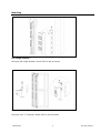
Full Length Bracket
Using the full length bracket, mount PDU to rack as shown
Mini "L" Brackets (SLB-4)
Using the mini “L” brackets, attach PDU to rack as shown
GM1084 Rev 2
6
Rev Date: 7/29/2014
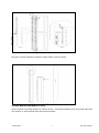
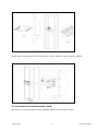
Vertical Extension Brackets (VCB-1)
Using the vertical extension brackets, attach PDU to rack as shown
Toolless Mounting Hardware (11621)
Secure toolless mounting buttons to PDU as shown. Use toolless buttons with key-holed slots built
into cabinet or with optional Geist key-holed brackets.
GM1084 Rev 2
7
Rev Date: 7/29/2014
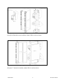
Toolless Full Length Bracket (TLFL)
Using full length toolless bracket and toolless mounting buttons, attach PDU to rack as shown
Single Side Mount 2 Unit Brackets (TSMX2)
Using single side mount 2 unit brackets and toolless mounting buttons, attach PDU to rack as
shown
GM1084 Rev 2
8
Rev Date: 7/29/2014
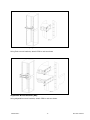
Offset/Side Mount Brackets (EZB-1)
Using the offset/side mount brackets, attach PDU to rack as shown.
7" Extension Brackets (XB-7)
Using the 7” extension brackets, attach PDU to rack as shown
GM1084 Rev 2
9
Rev Date: 7/29/2014
Flush Mount Brackets (FM)
Using flush mount brackets, attach PDU to rack as shown
Adjustable Mount Brackets (AM)
Using adjustable mount brackets, attach PDU to rack as shown
GM1084 Rev 2
10
Rev Date: 7/29/2014
Panel Mount Brackets (PM)
Using panel mount brackets, attach PDU to rack as shown
23" Conversion Mounting Brackets (23-RM)
Using conversion mounting brackets, attach 19” PDU to 23” rack as shown
GM1084 Rev 2
11
Rev Date: 7/29/2014
Cable Mount Bracket (CMB-1)
Attach cable mount bracket to PDU as shown; use tie-wraps to secure cords to bracket
19" Horizontal/Panel Mount Brackets (7938)
Using the 19” horizontal/panel mount brackets, attach PDU to rack as shown
GM1084 Rev 2
12
Rev Date: 7/29/2014
Optional Local Monitoring
Current Meter
The Geist CM-3 current meter is a low-power, high accuracy meter capable of measuring true
RMS Current. The value of current per output circuit is shown on an easy to read, 4-digit LED
Display. The display continuously scrolls through the three different measured values of output
circuit current. The Current Meter will automatically begin to display value of output current
when the PDU is connected to AC Mains power.
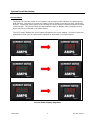
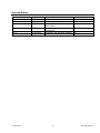
The CM-3 meter displays the circuit name followed by the circuit reading. All three circuits are
displayed and the cycle is continuously repeated as illustrated in the figure below.
Current Meter Display Sequence
GM1084 Rev 2
13
Rev Date: 7/29/2014
Optional Remote Monitoring
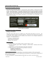
Current Monitoring Meter Overview
The Geist Current Monitoring Meter is a high accuracy meter capable of measuring true RMS
current. The value of line current per input phase and output circuit current is shown on an easy
to read, 4-digit LED Display.4 The display continuously scrolls through the different measured
values. The Current Monitoring Meter also provides access to measurement data and control
values through a web page, SNMP, or XML. The Current Monitoring Meter Instructions section of
this document will give more detailed information on the operation and functionality of the
Current Monitoring Meter.
Current Monitoring Meter
Current Monitoring Meter Instructions
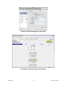
Setting an IP Address
The PDU comes preset with an IP address for initial setup and access to the unit. The
‘Configuration page’ contains the network properties. Access to the unit requires the IP address
to be known, the IP address may be manually reset should the user-configured address be
forgotten. The default address is:
IP Address: 192.168.123.123
Subnet Mask: 255.255.255.0
Gateway: 192.168.123.1
First time setup:
1. Connect PDU to your computer using a crossover cable or a hub.
2. On your computer, go to “Start > Settings > Control Panel > Network and Dial Up
Connections.”
3. Right Click on “Local Area Connection” and select “Properties.”
4. Select the option to “Use the following IP address” and enter:
IP address: 192.168.123.1
Subnet mask: 255.255.255.0
Default gateway: 192.168.123.15
Actual configuration of circuits measured by Current Monitoring Meter is PDU model specific.
Please contact Geist Customer Service department with questions on measurement configuration of
Current Monitoring Meters.
5
In some configurations, leaving the gateway field blank may resolve connectivity issues.
4
GM1084 Rev 2
14
Rev Date: 7/29/2014
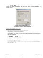
Click “OK” twice.
You can now access the unit using your web browser at the permanent IP address of
192.168.123.123.
Typical Network Card Settings for PC
or Laptop to connect to default IP address
First time setup (MacOS 10.5 and 10.6):
Open System Preferences via the Dock or the Apple menu.
Select “Network” under “Internet & Network.”
Select “Ethernet” from the list on the left side of the window and enter these settings on the
right side of the window:
Configure:
IP Address:
Subnet Mask:
Router:
Manually
192.168.123.1
255.255.255.0
Leave blank
Hit “Apply” and confirm the changes.
The unit should now be accessible in a web browser via the unit’s permanent IP address:
http://192.168.123.123/.
GM1084 Rev 2
15
Rev Date: 7/29/2014
MacOS X network settings for initial setup
Connecting to the PDU using a web browser
GM1084 Rev 2
16
Rev Date: 7/29/2014
LED Display
Each PDU has a built-in 4-digit LED display mounted midway down the chassis. The display
scrolls through the most recent current measurement (in amps) for each circuit, one at a time.
It displays a circuit name, pauses, and then displays the measurement. Momentarily press the
“Pause Scroll/IP Address Reset” button on the front of the PDU to pause the display on the current
measurement. While paused, the display will cycle back and forth between circuit name and
current reading every three seconds. Momentarily pressing the “Pause Scroll/IP Address Reset”
button again will skip ahead to the next circuit. The display will begin to scroll again thirty
seconds after the last button push.
Notes:
During the first cycle after the display has been paused, the display may take
up to six seconds to display a measurement.
Due to the time required to measure current accurately, the same reading may
be shown twice while the display is paused.
For reference:
Cr-1
Cr-2
Cr-3
Cr-4
Cr-5
Cr-6
=
=
=
=
=
=
Circuit
Circuit
Circuit
Circuit
Circuit
Circuit
1
2
3
4
5
6
Ph-A = Phase A
Ph-b = Phase B
Ph-C = Phase C
nEUt = Neutral
Fd-A = Feed A
Fd-B = Feed B
Viewing the IP Address/Resetting to Default IP
In the event that the IP address of the PDU is lost, it is possible to view the currently configured
IP address on the unit’s built-in LED display or reset the IP address to the default.
To view the IP address, press and hold the “Pause Scroll/IP Address Reset” button on the front
of the PDU for 20 seconds. The screen will stop displaying scrolling power data in order to display
the currently configured IP address. The display will show the IP address using the following
format:
c-IPaaa.bbb.ccc.ddd
The ‘’ indicates a pause and the aaa/bbb/ccc/ddd indicate a portion of the currently configured
IP address. The IP address will be displayed twice before normal scrolling continues.
CAUTION: If the “Pause Scroll/IP Address Reset” button is being held while the second
segment (bbb above) of the IP address is being displayed, the unit’s IP address will be
reset. To prevent this, release the button as soon as “c-IP” shows up on the display.
To reset the IP address to the backup IP address, press and hold the “Pause Scroll/IP Address
Reset” button on the front of the PDU for 20 seconds, at which point the display will show the
current IP address. Continue to hold the “Pause Scroll/IP Address Reset” button for 10 more
seconds and the display will switch to scrolling d-IP192.168.123.123. The IP
address is then reset to 192.168.123.123. The display will resume its normal function after the
display shows the IP address twice and the “Pause Scroll/IP Address Reset” has been released.
Once the IP address has been reset, the Setting an IP Address instructions should be followed to
access the unit.
GM1084 Rev 2
17
Rev Date: 7/29/2014
Rebooting the Meter
Should an Current Monitoring Meter with firmware version 1.36 or higher installed stop
responding to network traffic, it is possible to restore functionality by rebooting the meter without
removing power from the PDU it is enclosed in.
To reboot the meter, press and hold the “Pause Scroll/IP Address Reset” button on the front on
the PDU for 20 seconds. The screen will stop displaying scrolling power data in order to display
the currently configured IP address. The display will show the IP address using the following
format:
c-IPaaa.bbb.ccc.ddd
The ‘’ indicates a pause and the aaa/bbb/ccc/ddd indicate a portion of the currently configured
IP address. As soon as “c-IP” is displayed, release the “Pause Scroll/IP Address Reset” button.
Press and release the “Pause Scroll/IP Address Reset” button twice while the IP address is being
displayed. The screen will read “8.8.8.8.” for a few seconds and then resume scrolling normally,
indicating a successful reboot.
Web Page
The main interface to the PDU is its web page, accessible by typing the unit’s IP address into a
web browser. The web page is the source for the most up to date measurement of each circuit.
All measurements are in Amps.
SNMP/XML
In addition to HTML based web pages, the PDU presents its data via SNMP and an XML page.
To use the PDU with SNMP Client software, download the MIB from the link on the unit’s web
page and import it into the SNMP software. Contact the client software manufacturer for
instructions specific to their software. The PDU’s SNMP community comes preset to ‘public’. To
change this, go to the ‘Configuration’ page, enter a new name in the SNMP Community box and
hit “Save Changes.” In addition SNMP traps can be utilized to monitor a user set threshold for
each circuit, alarm settings and SNMP server settings are located on the ‘Configuration’ page.
The XML page provides terse output that is easily parsed by both humans and computers and is
useful for creating scripts to download and process information off the unit automatically. The
XML page is available at http://<IP address of meter>/data.xml.
Sample uses of XML and SNMP data are provided in the Sample Usage section of this document.
Firmware Updates/Instructions
The unit firmware is field upgradeable via FTP. Firmware updates and instructions are available
at the following website.
http://www.geistglobal.com/support
GM1084 Rev 2
18
Rev Date: 7/29/2014
Sample Usage
The simplest way to get data from a Current Monitoring Meter into a script is via the XML page.
Simply performing an HTTP GET (as a web browser does) on http://<IP address of
meter>/data.xml will download the XML file. The following examples assume that the meter’s IP
address is 192.168.123.123.
Perl Example:
using LWP::UserAgent;
my $ip = "192.168.123.123";
my $browser = LWP::UserAgent->new;
$browser->timeout(5);
my $xmlFile = $browser->get("http://" . $ip . "/data.xml" )->content;
At this point, $xmlFile will contain the text of data.xml, ready to be parsed however necessary.
Unix/Linux Command Line Example:
wget http://192.168.123.123/data.xml
This command will download data.xml into the current directory. At this point, the file is ready
to be used by any local application or script.
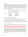
SNMP Example
Getif is a simple, free SNMP viewer for Windows available from:
http://www.wtcs.org/snmp4tpc/getif.htm
1. Drop the EM meter’s MIB file into Getif’s MIBs directory (Typically C:\Program Files\Getif
2.3.1\MIBs) and start Getif.
2. Type in the unit’s IP address into the box labeled “Host Name” and click the Start button.
Getif Configuration Example
GM1084 Rev 2
19
Rev Date: 7/29/2014
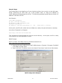
3. Click the ‘MBrowser’ tab and expand the .iso tree down to geistmfg.
4. Select geistmfg and click the Start button. Getif should start requesting data from the
unit via SNMP and display it in the large box at the bottom of the window.
Getif Geist Entry in MIB Table
Satellite Current Monitoring Meter Overview
The Geist Satellite Current Monitoring Meter is a high accuracy meter capable of measuring true
RMS current. The value of line current per input phase and output circuit current is shown on an
easy to read, 4-digit LED Display.6 The display continuously scrolls through the different
measured values. The Satellite Current Monitoring Meter reports data as an external sensor to
the Geist RSMINI163, RSE, RSO, RSM, RCX, RCM or RCU master units (not compatible with
RSMINI-P or FC-3-2) via an RJ-12 uplink. Up to 4 Satellite Current Monitoring units can be
connected to a single master.7
Actual configuration of circuits measured by Current Monitoring Meter is PDU model specific.
Please contact Geist Customer Service department with questions on measurement configuration of
Current Monitoring Meters.
7
Satellite Current Monitoring Meter unit and master unit must be grounded to the same ground.
6
GM1084 Rev 2
20
Rev Date: 7/29/2014
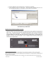
LED Display
Each PDU has a built-in 4-digit LED display mounted midway down the chassis. The display
scrolls through the most recent current measurement (in amps) for each circuit, one at a time.
It displays a circuit name, pauses, and then displays the measurement. Momentarily press the
“Scroll” button on the front of the PDU to pause the display on the current measurement. While
paused, the display will cycle back and forth between circuit name and current reading every
three seconds. Momentarily pressing the “Scroll” button again will skip ahead to the next circuit.
The display will begin to scroll again thirty seconds after the last button push.
Notes:
During the first cycle after the display has been paused, the display may take
up to six seconds to display a measurement.
Due to the time required to measure current accurately, the same reading may
be shown twice while the display is paused.
For reference:
Cr-1
Cr-2
Cr-3
Cr-4
Cr-5
Cr-6
=
=
=
=
=
=
Circuit
Circuit
Circuit
Circuit
Circuit
Circuit
1
2
3
4
5
6
Ph-A = Phase A
Ph-b = Phase B
Ph-C = Phase C
nEUt = Neutral
Fd-A = Feed A
Fd-B = Feed B
DM-16 PDU Display on R-Series Master Unit
GM1084 Rev 2
21
Rev Date: 7/29/2014
Serial Communication
Satellite Current Monitoring Meter is also capable of serial communication via a serial terminal or
console. The RJ-12 port on the unit can be connected to other serial devices via an adapter cable.
The serial interface can be used to view unit version, # of channels, and current measurement
data.
RJ-12 Pin-Out for Serial Cable
DB-9 to RJ-12 Pin-Out Diagram
Pins 1-3 on RJ-12 connector must be left un-terminated for proper communication.
located closest to the red reset button on the meter.
Pin 1 is
Serial Command List
GM1084 Rev 2
22
Rev Date: 7/29/2014
Service/Tech Support
Service and Maintenance
No service or maintenance is required. Do not attempt to open the PDU or you may void the
warranty. No serviceable parts inside. It is recommended that power be removed from the unit
before installing or removing any equipment.
More Technical Support
http://www.geistglobal.com
(800) 432-3219
Email: [email protected]
Or contact your distributor.
GM1084 Rev 2
23
Rev Date: 7/29/2014
Table of Figures
Full Length Bracket................................................................................................................................................................... 6
Mini "L" Brackets (SLB-4) ...................................................................................................................................................... 6
Vertical Extension Brackets (VCB-1) ...................................................................................................................................... 7
Toolless Mounting Hardware (11621)...................................................................................................................................... 7
Toolless Full Length Bracket (TLFL) ...................................................................................................................................... 8
Single Side Mount 2 Unit Brackets (TSMX2) ......................................................................................................................... 8
Offset/Side Mount Brackets (EZB-1) ....................................................................................................................................... 9
7" Extension Brackets (XB-7)................................................................................................................................................... 9
Flush Mount Brackets (FM) ................................................................................................................................................... 10
Adjustable Mount Brackets (AM) .......................................................................................................................................... 10
Panel Mount Brackets (PM) ................................................................................................................................................... 11
23" Conversion Mounting Brackets (23-RM) ....................................................................................................................... 11
Cable Mount Bracket (CMB-1) .............................................................................................................................................. 12
19" Horizontal/Panel Mount Brackets (7938) ....................................................................................................................... 12
Current Meter Display Sequence ........................................................................................................................................... 13
Current Monitoring Meter ..................................................................................................................................................... 14
Typical Network Card Settings for PC .................................................................................................................................. 15
or Laptop to connect to default IP address ........................................................................................................................... 15
MacOS X network settings for initial setup .......................................................................................................................... 16
Connecting to the PDU using a web browser ........................................................................................................................ 16
Getif Configuration Example ................................................................................................................................................. 19
Getif Geist Entry in MIB Table .............................................................................................................................................. 20
DM-16 PDU Display on R-Series Master Unit ...................................................................................................................... 21
DB-9 to RJ-12 Pin-Out Diagram ............................................................................................................................................ 22
GM1084 Rev 2
24
Rev Date: 7/29/2014
Revision History
Revision
1.0
1.1
1.2
Date
4/8/2009
7/1/2009
6/30/2010
1.3
1/24/11
1.4
2.0
6/22/2012
7/29/2014
GM1084 Rev 2
Notes
Original Published Version
Added Link Speed Information
Updated Current Monitoring
Meter Name
Added Satellite Current
Monitoring
Changed Logo and Web Address
Changed Company Name
25
Approved By
BP
BP
BP
SC & BP
SR
QN
Rev Date: 7/29/2014