1
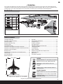
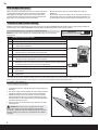
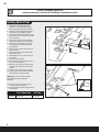
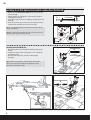
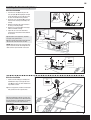
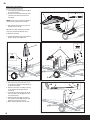
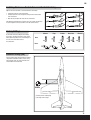
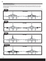
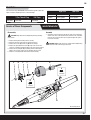
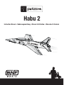
Habu 2 Instruction Manual • Bedienungsanleitung • Manuel d’utilisation • Manuale di Istruzioni EN NOTICE All instructions, warranties and other collateral documents are subject to change at the sole discretion of Horizon Hobby, Inc. For up-to-date product literature, visit www.horizonhobby.com and click on the support tab for this product. Meaning of Special Language: The following terms are used throughout the product literature to indicate various levels of potential harm when operating this product: NOTICE: Procedures, which if not properly followed, create a possibility of physical property damage AND little or no possibility of injury. CAUTION: Procedures, which if not properly followed, create the probability of physical property damage AND a possibility of serious injury. WARNING: Procedures, which if not properly followed, create the probability of property damage, collateral damage, and serious injury OR create a high probability of superficial injury. WARNING: Read the ENTIRE instruction manual to become familiar with the features of the product before operating. Failure to operate the product correctly can result in damage to the product, personal property and cause serious injury. This is a sophisticated hobby product. It must be operated with caution and common sense and requires some basic mechanical ability. Failure to operate this Product in a safe and responsible manner could result in injury or damage to the product or other property. This product is not intended for use by children without direct adult supervision. Do not attempt disassembly, use with incompatible components or augment product in any way without the approval of Horizon Hobby, Inc. This manual contains instructions for safety, operation and maintenance. It is essential to read and follow all the instructions and warnings in the manual, prior to assembly, setup or use, in order to operate correctly and avoid damage or serious injury. Age Recommendation: Not for children under 14 years. This is not a toy. Safety Precautions and Warnings As the user of this product, you are solely responsible for operating in a manner that does not endanger yourself and others or result in damage to the product or the property of others. • Always keep a safe distance in all directions around your model to avoid collisions or injury. This model is controlled by a radio signal subject to interference from many sources outside your control. Interference can cause momentary loss of control • Always operate your model in open spaces away from full-size vehicles, traffic and people. • Always carefully follow the directions and warnings for this and any optional support equipment (chargers, rechargeable battery packs, etc.). • Always keep all chemicals, small parts and anything electrical out of the reach of children. 2 • Always avoid water exposure to all equipment not specifically designed and protected for this purpose. Moisture causes damage to electronics. • Never place any portion of the model in your mouth as it could cause serious injury or even death. • Never operate your model with low transmitter batteries. • Always keep aircraft in sight and under control. • Always use fully charged batteries. • Always keep transmitter powered on while aircraft is powered. • Always remove batteries before disassembly. • Always keep moving parts clean. • Always keep parts dry. • Always let parts cool after use before touching. • Always remove batteries after use. • Always ensure failsafe is properly set before flying. • Never operate aircraft with damaged wiring. • Never touch moving parts. EN – Introduction – You are about to take flight with one of the hottest electric ducted fans ever built. Its potent one-two punch of speed and precision aerobatic ability will make every flight one to remember. Before you take to the sky though, you must read through this manual. The ParkZone® Habu 2 can cover a lot of ground in a hurry and things happen fast. The better understanding you have of its performance and systems prior to your first flight, the better that flight will be. Box Contents Included Screws and Fasteners Size Qty 2X8mm 6 2.5X8mm 7 2.5X8mm (black) 4 3X10mm 4 3X25mm 3 BIND PLUG Spare fasteners may be included. Table of Contents Low Voltage Cutoff (LVC) ................................................................... 4 Transmitter and Receiver Binding...................................................... 4 Installing the Battery ......................................................................... 4 Arming the ESC Before Flight ............................................................ 5 Installing the Wing ............................................................................ 5 Installing Optional Flaps .................................................................... 6 Installing the E-flite Optional Retractable Landing Gear ..................... 7 Installing the E-flite Optional Retractable Landing Gear (Continued)... 8 Installing the Fixed Landing Gear ...................................................... 9 Attaching the Tail ............................................................................ 10 Installing Clevises on Control Horns and Control Centering .............. 11 Factory Settings .............................................................................. 11 Center of Gravity (CG) ..................................................................... 11 Control Direction Test ...................................................................... 12 36.3 in (920mm) Dual Rates ...................................................................................... 13 Service of Power Components ........................................................ 13 Preflight Checklist ........................................................................... 14 Flying Tips and Repairs ................................................................... 14 Post Flight Checklist ....................................................................... 15 AMA National Model Aircraft Safety Code ........................................ 15 Troubleshooting Guide .................................................................... 16 Limited Warranty ............................................................................ 17 Contact Information ........................................................................ 18 Compliance Information for the European Union .............................. 18 Replacement Parts.......................................................................... 67 Optional Parts ................................................................................. 68 Parts Contact Information ............................................................... 68 Installed Ducted Fan Unit: Delta-V® 15 69mm EDF Fan Unit (EFLDF15) Motor: BL15 Ducted Fan Motor, 3200Kv (EFLM3215DF) 43.3 in (1100mm) ESC: 60-Amp Pro Switch-Mode BEC Brushless ESC (EFLA1060) (5) Servos Receiver: Spektrum™ AR600 2.4GHz DSM2®/DSMX® full range sport receiver Needed to Complete Battery: 3200mAh 14.8V 4-cell 30C Li-Po (EFLB32004S30) Battery Charger: 3–4 cell Li-Po battery charger (PKZ7040) Weight: (RTF ) 51.8 oz (1470 g)* Weight: (RTF with Flaps and Retracts) 54.7 oz (1550 g)* * Weight is with E-Flite 3200mAh 4 cell Lipo (EFLB32004S30) Required Transmitter: Full-Range 2.4GHz with Spektrum™ DSM2/DSMX technology. To register your product online, visit www.parkzone.com 3 EN Low Voltage Cutoff (LVC) When a Li-Po battery is discharged below 3V per cell, it will not hold a charge. The ESC protects the flight battery from over-discharge using Low Voltage Cutoff (LVC). Before the battery charge decreases too much, LVC removes power supplied to the motor. Power to the motor pulses, showing that some battery power is reserved for flight control and safe landing. When the motor pulses, land the aircraft immediately and recharge the flight battery. Disconnect and remove the Li-Po battery from the aircraft after use to prevent trickle discharge. Charge your Li-Po battery to about half capacity before storage. During storage, make sure battery charge does not fall below 3V per cell. Transmitter and Receiver Binding Binding is the process of programming the receiver of the control unit to recognize the GUID (Globally Unique Identifier) code of a single specific transmitter. You need to ‘bind’ your chosen Spektrum DSM2/DSMX technology equipped aircraft transmitter to the receiver for proper operation. Please visit www.bindnfly.com for a complete list of compatible transmitters. NOTICE: When using a Futaba transmitter with a Spektrum DSM® module, you must reverse the throttle channel. Binding Procedure Reference Table Install a bind plug in the receiver bind port. 5. Connect the flight battery to the ESC. The ESC will produce a series of sounds. One long tone, then three short tones confirm that the LVC is set for the ESC. 6. Power on the ESC switch. The receiver LED will begin to flash rapidly. 7. Power on the transmitter while holding the transmitter bind button or switch. Refer to your transmitter’s manual for binding button or switch instructions. 8. When the receiver binds to the transmitter, the light on the receiver will turn solid and the ESC will produce a series of four ascending tones. The tones will indicate the ESC is armed, provided the throttle stick and throttle trim are low enough to trigger arming. 9. Remove the bind plug from the bind port. 2.4GHz DSM® TECHNOLOGY 6CH SPORT RECEIVER 2048 RUDD 4. GEAR Move the transmitter controls to neutral (flight controls: rudder, elevators and ailerons) or to low positions (throttle, throttle trim).* AUX 1 Make sure the transmitter is powered off. 3. AILE 2. ELEV Read the transmitter instructions for binding to a receiver (location of transmitter’s Bind control). BIND/DATA 1. THRO BIND PLUG 10. Safely store the bind plug (some owners attach the bind plug to their transmitter using two-part loops and clips). 11. The receiver should retain the binding instructions received from the transmitter until another binding is done. * The throttle will not arm if the transmitter’s throttle control is not put at the lowest position. If you encounter problems, follow binding instructions and refer to the transmitter troubleshooting guide for other instructions. If needed, contact the appropriate Horizon Product Support office. Installing the Battery 1. Carefully lift the front of the canopy (A) and pull the canopy forward and off the fuselage. 2. Place the blue battery connector toward the front of the airplane and install the flight battery (B) all the way to the front of the battery compartment. 3. If binding the aircraft receiver to the transmitter, refer to the transmitter manual’s binding instructions. If the aircraft is already bound to the transmitter, always power on the transmitter before connecting the flight battery to the ESC connector in the aircraft. 4. Install the canopy on the fuselage. Make sure the magnets on the canopy and fuselage meet. CAUTION: Always disconnect the Li-Po battery from the aircraft receiver when not flying to avoid over-discharging the battery. Batteries discharged to a voltage lower than the lowest approved voltage may become damaged, resulting in loss of performance and potential fire when batteries are charged. 4 A B EN Arming the ESC Before Flight 1 • Lower throttle and throttle trim to lowest settings. 2 Power on Transmitter 3 • Connect battery to ESC. 4 • Power on ESC switch. Wait 5 seconds Continuous LED Series of tones Installing the Wing B A If you plan on installing optional flaps or retracts, you must do so before installing the wing. Please proceed to the following pages for instructions. 1. Remove the canopy from the fuselage. 2. Turn the wing and fuselage so their bottom sides face up. 3. Slide the two guide pins (A) of the wing into the two holes in the fuselage. 4. Connect both aileron servo connectors (B) to the aileron Y-harness. The left and right servo connectors do not have to be connected to a particular side of the Y-harness. 5. Align and attach the wing to the fuselage using 3 screws (C). The 2 rear screws are longer than the front screw. 6. When needed, disassemble in reverse order. CAUTION: DO NOT crush or otherwise damage wiring when attaching the wing to the fuselage. C 3 X 25mm NOTICE: Use of CA (cyanocrylate adhesive) accelerant on your model can damage paint. DO NOT handle the model until the accelerant fully dries. 5 EN If you are assembling your aircraft using only stock parts, proceed to the Installing the Landing Gear section. Installing Optional Flaps 1. Install the left and right flap servos (A) (PKZ1081 x 2, sold separately) in the wing pocket using hot glue or double-sided tape. 2. Install the control horns (B) and plates (C) on the wing using 2 screws (D) in each horn. 3. Install a connector and clevis (E) in the second innermost hole of the servo arm and outer hole of the control horn. 4. Carefully cut a wedge of foam from the flap hinge near the aileron hinge (see illustration). 5. Carefully cut a small amount of foam at the flap and wing root so the flap moves freely (see illustration). 6. Remove the tape to put the servo wires in the wing channel (F). 7. Put the flap servo wires in the wing channel with the aileron wires. 8. Install the flap servo connector in the hole at the wing root. 9. Place tape over the channel. 10. Cut a small amount of tape at the flap servo to let the servo arm move freely. 11. Adjust the clevis so the flap is not pulled fully against the wing at the hinge when the flap is operated. 12. Install the servo connectors in the fuselage. 13. Install the wing on the fuselage using installation instructions on the previous page. NOTICE: Make sure wires are not crushed or damaged when the wing is attached to the fuselage. 14. Attach the servo connectors to the correct receiver channels or Y-harnesses. 15. Do a control test of the flaps using your aircraft and transmitter. 1/2 or Takeoff Flap Flap down 6 13mm down Full Flaps 25mm down F A E B D C EN Installing the E-flite Optional Retractable Landing Gear Before installing the optional E-flite® retractable landing gear (EFLG110), collect the wheels and necessary fasteners from the included aircraft parts. 2 in (51mm) A Setting up the Retractable Nose Gear Strut For Your aircraft 1 in (25.4 mm) B The nose gear strut included with the electric retracts does not let the nose gear fully retract into the fuselage. Cut, then bend the nose strut so that the nose wheel extends and retracts freely. 15° 1. Measure 2 inches (51mm) below the coil, then mark and cut off the strut (A). 2 Measure and mark about 1 inch (25.4mm) below the coil, then bend the strut (B) to a 15° angle (approximately). Ensure the bend does not angle the strut left or right or the gear may not steer straight. 3. Install your aircraft’s nose wheel (C) on the retract strut (D) using an axle (E), axle screws, wheel collar (F) and set screw. D E C F Tip: Use a metal file to make flat spots on both sides of the strut so the axle screws can be tightened. Installing Retractable Nose Gear 1. Install the retract harness in the fuselage by connecting the harness to the 3 gear extensions and the GEAR port on the receiver. 2. Where installed, remove the nose gear plate and 6 screws from the nose. 3. Replace the 5-hole steering servo arm with the included 2-hole servo arm (G) using the installed screw as shown. 4. Connect the clevis (J) to the gear (H) using the screw (I). 5. Connect the linkage (K) to the inner most hole of the steering servo arm using the included snap link (L). 6. Connect the retract connnector (M) to the gear harness extension in the nose compartment. 7. Install the nose retract (N) in the fuselage using 4 screws (O) included with the aircraft. Carefully align and install the screws in the existing holes in the nose compartment. Some force will be required to cut threads in the plastic using these screws. L G H I K J Q NOTICE: Always ensure the aircraft rolls straight when the rudder control on your transmitter is at neutral. P 2.5 X 8mm O 8. Where needed, install the outer plate (P) on the nose using 6 screws (Q). 9. Operate the nose gear to ensure it moves freely and operates correctly. 3 X 10mm Tip: If desired for scale appearance, install the nose gear door (R) on the strut. Tip: For increased steering travel, move the pushrod to the outer hole of the servo arm. M N Setting up the Retractable Main Struts For Your Aircraft R 7 EN Installing the E-flite Optional Retractable Landing Gear (Continued) 1. Measure and mark 2.25 inches (57.2mm) below the coil of the strut, then cut off the strut (A). 2. Install the included rear wheels (B) on the retract axles (C), using wheel collars (D) and set screws (E). 3. Loosely fit the retract axles on the rear landing gear struts (F) using the axle screws (G). 4. Ensure the wheels move freely in and out of the wheel wells when extending and retracting, then tighten the axle screws on the struts. 2.25 in (57.2mm) A G Tip: Use a metal file to make flat spots on both sides of the strut so the axle screws can be tightened. F C B Tip: Apply a small amount of threadlock to the axle screws and set screws in the wheel collars to keep the wheels on the struts. D E Installing Retractable Main Gear 1. Where installed, remove 8 screws (H) and the landing gear doors (I) from the wing. 2. Install the main retracts (J) in the wing using the 8 screws removed from the landing gear doors. 3. Connect the main retracts to the gear harness extensions (K) in the fuselage. H 3 X 25mm I Tip: If desired for scale appearance, install the left and right main gear doors (L) on the respective struts. Operate the landing gear to ensure they move freely and operate correctly. J K L 8 EN Installing the Fixed Landing Gear Nose Gear Installation J 1. Insert the nose strut (A) into the post in the nose gear plate (B) while aligning the flat spot on the strut with the set screw (C). The coil on the nose strut should be facing rearward. 2. Connect the nose gear linkage (D) to the innermost hole in the steering servo arm (E) in the fuselage. 3. Attach the clevis (F) to the outer most hole in the nose gear steering arm (G). 4. Attach the nose gear plate (H) to the fuselage with the 6 included screws (I). 5. Tighten the set screw on the strut. Where needed, apply a small amount of threadlock to the set screw. Tip: If desired for scale appearance, install the nose gear cover (J) on the strut. Tip: For increased steering travel, move the pushrod out on the servo arm one hole at a time. A B C E D G F NOTICE: Adjust the clevis on the nose wheel steering arm so that the aircraft rolls straight when the rudder control on your transmitter is at neutral. I 2.5 X 8mm H Main Gear Installation 1. Install each main landing gear strut (K) on the installed doors using 2 screws (L) and a strut cover (M). The coils on the struts should be facing rearward as shown. Tip: For scale appearance, install the left and right main gear doors on the respective struts. L K 2.5 X 8mm M Tip: For belly landings, install the nose gear cover plate using the included 6 screws. We recommend that you install the 2 included skids in the fuselage behind the nose gear plate and in front of the exhaust nozzle. 9 EN Attaching the Tail 1. Loosely align the horizontal stabilizer unit (A) on the rear of the fuselage. 2. Correctly connect the rudder and elevator servo connectors to the marked connectors in the fuselage (B). B A NOTICE: Ensure no wires are pinched or damaged when the tail unit is attached to the fuselage. 3. Align and install the unit on the top of the rear fuselage using 2 screws (C). Tip: Remove the rudder linkage from the rudder servo arm so the right mounting plate can be installed on the vertical fin. 4. Install the tube (D) in the holes in the vertical fin (E) and in the top of the stabilizer unit. I E H 2.5 X 8mm C 2.5 X 8mm D F G 5. Align and press the tail cone (F) on the rear of the fuselage, then apply the included tape (G) to the tailcone and fuselage. 6. Attach the vertical fin to the stabilizer unit using the left and right mounting plates (H) and 5 screws (I). 7. Put the Z-bend of the linkage (J) in the second hole of the rudder servo arm (K) (the hole next to the outermost hole). 8. Attach the linkage clevis (L) to the outer hole of the rudder control horn (M). Ensure the tube tightens the clevis on the control horn. 9. Where needed, disassemble in reverse order. 10 M L J K EN Installing Clevises on Control Horns and Control Centering Tip: Turn the clevis clockwise or counterclockwise on the linkage. • Pull the tube from the clevis to the linkage. • Carefully spread the clevis and put the clevis pin into the desired hole in the control horn. • Move the tube to tighten the clevis onto the control horn. After binding a transmitter to the model receiver, set all trims and sub-trims to 0, then adjust the clevises by hand to center the control surfaces. 1. 4. 2. 5. 3. 6. Factory Settings Fly the model at factory settings before making any changes. For pilots who wish for more control throw, adjust the position of the control linkages on the servo arms and control horns for increased travel. Ailerons Flaps Rudder Nose Gear Elevator Arms Servo Strut Horns Center of Gravity (CG) Place the battery all the way forward in the battery compartment and hold the battery in place using hook and loop straps. It is easiest to balance the aircraft with the aircraft inverted. 102mm (4 inches) from the leading edge of the wing at the fuselage. 11 EN Control Direction Test Bind your aircraft and transmitter before performing these tests. Move the controls on the transmitter to ensure the aircraft control surfaces move correctly. After doing the Control Test, correctly set the failsafe. Make sure the transmitter controls are at neutral and the throttle and throttle trim are in the low position, then rebind the model to your transmitter. If the receiver loses its link to the transmitter, the failsafe automatically moves the controls and throttle settings to those made at binding. Elevator Up Elevator Down Elevator Aileron Stick Left Stick Right Stick Left Rudder Stick Left Stick Right Stick Left Optional Flaps Flaps up Stick Left 12 Flaps Down EN Dual Rates We recommend using a DSM2/DSMX aircraft transmitter capable of dual rates. Adjust according to individual preferences after initial flight. 1/2 or Takeoff Flap Flap down Full Flaps 13mm down 25mm down Service of Power Components High Rate Low Rate Aileron 19mm up/down 13mm up/down Elevator 16mm up/down 13mm up/down Rudder 25mm left/right 19mm left/right MAINTENANCE Disassembly Assembly CAUTION: Always disconnect the flight battery before performing motor service. 1. Assemble in reverse order. Correctly align the colors of the motor wires with the wire colors of the ESC. Ensure the front of the rotor is installed facing the nose of the aircraft. A tool is required to tighten the spinner on the rotor and collet. 1. 2. 3. 4. Remove the wing, disconnecting servos as needed. Disconnect the motor connectors from the ESC connectors. Remove the 4 screws (A) and fan unit (B) from the fuselage. Remove the spinner (C) from the rotor (D), using a tool such as a hex wrench or screwdriver inserted through the hole in the tip of the spinner. 5. Remove the rotor, backplate (E) and collet (F) from the motor (G). Tap lightly on the end of the collet to free the backplate from the collet. 6. Remove 2 screws (H) and the motor from the motor mount (I). C D E F I CAUTION: DO NOT handle the fan unit or ESC while the flight battery is connected to the ESC. Personal injury could result. G A 2.5 X 6mm H 3 X 5mm B Not all wiring shown. 13 EN Preflight Checklist Before Flying Check List Before Flying Check List 1. Charge flight battery. 6. Adjust flight controls and transmitter. 2. Install flight battery in aircraft (once it has been fully charged). 7. Perform a radio system Range Check. 3. Bind aircraft to transmitter. 8. Find a safe and open area. 4. Make sure linkages move freely. 9. Plan flight for flying field conditions. 5. Perform Control Direction Test with transmitter. Flying Tips and Repairs Range Check your Radio System After final assembly, range check the radio system with the Habu 2. Refer to your specific transmitter instruction manual for range test information. Flying Always choose a wide-open space for flying your ParkZone Habu 2. It is ideal that you fly at a sanctioned flying field. If you are not flying at an approved site, always avoid flying near houses, trees, wires and buildings. You should also be careful to avoid flying in areas where there are many people, such as busy parks, schoolyards or soccer fields. Consult local laws and ordinances before choosing a location to fly your aircraft. Landing CAUTION: Always lower the throttle after landing to avoid accidental intake of materials, which could result in possible damage to the rotor and/or motor and cause personal injury. For your first flights, set your transmitter timer or a stopwatch to 3 1/2 minutes. Adjust your timer for longer or shorter flights once you have flown the model. When the motor pulses, land the aircraft immediately and recharge the flight battery. It is not recommended to continuously fly the battery to LVC. This is a go-where-you-point-it aircraft. It tracks very straight and is capable of many maneuvers. It has a wide speed range, from full throttle high-speed passes to slow flight, but has great handling qualities throughout its entire flight envelope. If this is your first ducted fan aircraft, just remember that because there is no prop blast blowing air over the control surfaces, the controls will not be as responsive at low speeds. The aircraft is easy to fly, but because it can reach a very high speed, plan your flight path to avoid obstacles or people. This aircraft is very easy to land and can reward you with very smooth scalelike touchdowns. Approach the runway with a 1/4 to 1/8 throttle. Use the power to control altitude and the elevator to control angle of attack. Once your glide path is established, fly the aircraft down to about a foot (30 cm) off the runway. Gradually reduce power and flare the aircraft to touch down on the main wheels first. Reduce elevator input to set the nosewheel on the ground and steer with the rudder stick until the aircraft has come to a stop. You can hold the nosewheel off the runway while landing for aerodynamic braking, however, be aware that the aircraft can hop back into the air if a gust of wind or too much elevator input is given while holding the nose off the ground. Always make wide turns with the nose gear to avoid tipping the aircraft on its side. Hand launch Flaps It is advisable to have a helper for the first few hand launches. Hold the airplane behind the wing with the throwing hand and support the nose with the opposite hand. Run the motor up to full throttle and give a FIRM throw straight ahead. The aircraft should be launched firmly with the nose up 5–10 degrees and directly into the wind. Do not throw nose down. ROG Takeoff Taxi into position on the runway. Avoid sharp turns when taxiing at higher speeds to avoid tipping the aircraft on its side. Once in position on the runway, start your timer. Hold 1/2 to full up elevator at the start of the takeoff roll to get weight off the nosewheel and allow for smoother takeoffs. Steer with the rudder, and, as speed increases, reduce the up elevator input to 1/4 to 1/2 up elevator. The airplane will lift off when flying speed is reached. Belly Landing If landing on grass without the landing gear, use the same approach as if flying with landing gear. Start your flare with the power off about 1 foot (30 cm) above the ground and hold the nose off until the tail touches down. Try to keep the wings level to prevent clipping a wing on the ground and turning the aircraft sideways. 14 When using the optional flaps, the takeoffs and landings are shorter. During landing, the flaps allow a landing approach to be steeper with less throttle. The flaps make the plane come in at a slower airspeed and make it easier to flare and settle in for a smooth landing. When deploying the flaps, slow the aircraft down to 1/4 throttle. If the flaps are deployed when the aircraft is at a higher speed, the aircraft will pitch up. If your transmitter is capable, a slight amount of down elevator to flap mixing will reduce the pitch up tendency. NOTICE: When finished flying, never keep the aircraft in the sun. Do not store it in a hot, enclosed area such as a car. Doing so can damage the foam. Repairs Thanks to the Z-Foam™ construction, repairs to most of the foam can be made using virtually any adhesive (hot glue, regular CA (cyanocrylate adhesive), epoxy, etc). NOTICE: Use of CA accelerant on your model can damage paint. DO NOT handle the model until the accelerant fully dries. When parts are not repairable, see the Replacement Parts List for ordering by item number. EN Post Flight Checklist After Flying Check List 1. Disconnect flight battery from ESC (Required for Safety and battery life). 2. Power off transmitter. 3. Remove flight battery from aircraft. 4. Recharge flight battery. After Flying Check List 5. Repair or replace all damaged parts. 6. Store flight battery apart from aircraft and monitor the battery charge. 7. Make note of flight conditions and flight plan results, planning for future flights. AMA National Model Aircraft Safety Code Effective January 1, 2011 A. GENERAL A model aircraft is a non-human-carrying aircraft capable of sustained flight in the atmosphere. It may not exceed limitations of this code and is intended exclusively for sport, recreation and/or competition. All model flights must be conducted in accordance with this safety code and any additional rules specific to the flying site. 1. Model aircraft will not be flown: (a) In a careless or reckless manner. (b) At a location where model aircraft activities are prohibited. 2. Model aircraft pilots will: (a) Yield the right of way to all man carrying aircraft. (b) See and avoid all aircraft and a spotter must be used when appropriate. (AMA Document #540-D-See and Avoid Guidance.) (c) Not fly higher than approximately 400 feet above ground level within three (3) miles of an airport, without notifying the airport operator. (d) Not interfere with operations and traffic patterns at any airport, heliport or seaplane base except where there is a mixed use agreement. (e) Not exceed a takeoff weight, including fuel, of 55 pounds unless in compliance with the AMA Large Model Aircraft program. (AMA Document 520-A) (f) Ensure the aircraft is identified with the name and address or AMA number of the owner on the inside or affixed to the outside of the model aircraft. (This does not apply to model aircraft flown indoors). (g) Not operate aircraft with metal-blade propellers or with gaseous boosts except for helicopters operated under the provisions of AMA Document #555. (h) Not operate model aircraft while under the influence of alcohol or while using any drug which could adversely affect the pilot’s ability to safely control the model. (i) Not operate model aircraft carrying pyrotechnic devices which explode or burn, or any device which propels a projectile or drops any object that creates a hazard to persons or property. Exceptions: • Free Flight fuses or devices that burn producing smoke and are securely attached to the model aircraft during flight. • Rocket motors (using solid propellant) up to a G-series size may be used provided they remain attached to the model during flight. Model rockets may be flown in accordance with the National Model Rocketry Safety Code but may not be launched from model aircraft. • Officially designated AMA Air Show Teams (AST) are authorized to use devices and practices as defined within the Team AMA Program Document (AMA Document #718). (j) Not operate a turbine-powered aircraft, unless in compliance with the AMA turbine regulations. (AMA Document #510-A). 3. Model aircraft will not be flown in AMA sanctioned events, air shows or model demonstrations unless: (a) The aircraft, control system and pilot skills have successfully demonstrated all maneuvers intended or anticipated prior to the specific event. (b) An inexperienced pilot is assisted by an experienced pilot. 4. When and where required by rule, helmets must be properly worn and fastened. They must be OSHA, DOT, ANSI, SNELL or NOCSAE approved or comply with comparable standards. B. RADIO CONTROL 1. All pilots shall avoid flying directly over unprotected people, vessels, vehicles or structures and shall avoid endangerment of life and property of others. 2. A successful radio equipment ground-range check in accordance with manufacturer’s recommendations will be completed before the first flight of a new or repaired model aircraft. 3. At all flying sites a safety line(s) must be established in front of which all flying takes place (AMA Document #706-Recommended Field Layout): (a) Only personnel associated with flying the model aircraft are allowed at or in front of the safety line. (b) At air shows or demonstrations, a straight safety line must be established. (c) An area away from the safety line must be maintained for spectators. (d) Intentional flying behind the safety line is prohibited. 4. RC model aircraft must use the radio-control frequencies currently allowed by the Federal Communications Commission (FCC). Only individuals properly licensed by the FCC are authorized to operate equipment on Amateur Band frequencies. 5. RC model aircraft will not operate within three (3) miles of any pre-existing flying site without a frequency-management agreement (AMA Documents #922-Testing for RF Interference; #923- Frequency Management Agreement) 6. With the exception of events flown under official AMA Competition Regulations, excluding takeoff and landing, no powered model may be flown outdoors closer than 25 feet to any individual, except for the pilot and the pilot’s helper(s) located at the flight line. 7. Under no circumstances may a pilot or other person touch a model aircraft in flight while it is still under power, except to divert it from striking an individual. This does not apply to model aircraft flown indoors. 8. RC night flying requires a lighting system providing the pilot with a clear view of the model’s attitude and orientation at all times. 9. The pilot of a RC model aircraft shall: (a) Maintain control during the entire flight, maintaining visual contact without enhancement other than by corrective lenses prescribed for the pilot. (b) Fly using the assistance of a camera or First-Person View (FPV) only in accordance with the procedures outlined in AMA Document #550. Please see your local or regional modeling association’s guidelines for proper, safe operation of your model aircraft. 15 EN Troubleshooting Guide Problem Aircraft will not respond to throttle but responds to other controls Possible Cause Solution Throttle is not set to lowest stick postiion and/or throttle trim is too high Reset controls with throttle stick and throttle trim at lowest setting Throttle servo travel is lower than 100% Make sure throttle servo travel is 100% or greater Throttle channel is reversed Reverse throttle channel on transmitter Extra fan noise or extra vibration Damaged rotor and spinner, collet or motor Replace damaged parts Rotor is out of balance Balance or replace rotor Reduced flight time or aircraft underpowered Flight battery charge is low Completely recharge flight battery Flight battery is damaged Replace flight battery and follow flight battery instructions Aircraft will not Bind (during binding) to transmitter Aircraft will not link (after binding) to transmitter Control surface does not move Flight conditions may be too cold Make sure battery is warm before use Battery capacity may be too low for flight conditions Replace battery or use a larger capacity battery Transmitter is too near aircraft during binding process Move powered transmitter a few feet from aircraft, disconnect and reconnect flight battery to aircraft Aircraft or transmitter is too close to large metal object Move aircraft or transmitter away from large metal object Bind plug is not installed correctly Install bind plug and bind aircraft to transmitter Flight battery/Transmitter battery charge is too low Replace/recharge batteries ESC switch is off Power on ESC switch Transmitter is too near aircraft during linking process Move powered transmitter a few feet from aircraft, disconnect and reconnect flight battery to aircraft Aircraft or transmitter is too close to large metal object Move aircraft or transmitter away from large metal object Bind plug is left installed Rebind transmitter to aircraft and remove bind plug before cycling power Aircraft bound to different model memory (ModelMatch™ radios only) Select correct model memory on transmitter Flight battery/Transmitter battery charge is too low Replace/recharge batteries Transmitter may have been bound to a different model (using different DSM Protocol) Bind aircraft to transmitter ESC switch is off Power on ESC switch Control surface, control horn, linkage or servo damage Replace or repair damaged parts and adjust controls Wire is damaged or connections are loose Do a check of wires and connections, connect or replace as needed Transmitter is not bound correctly or the incorrect model was selected Re-bind or select correct model in transmitter BEC (Battery Elimination Circuit) of the ESC is damaged Replace ESC ESC switch is off Power on ESC switch Controls reversed Transmitter settings are reversed Do the Control Direction Test and adjust controls on transmitter appropriately Motor power pulses then motor loses power ESC uses default soft Low Voltage Cutoff (LVC) Recharge flight battery or replace battery that is no longer performing 16 Weather conditions might be too cold Postpone flight until weather is warmer Battery is old, worn out or damaged Replace battery Battery C rating might be too small Use recommended 30C battery EN Limited Warranty What this Warranty Covers Inspection or Services Horizon Hobby, Inc. (“Horizon”) warrants to the original purchaser that the product purchased (the “Product”) will be free from defects in materials and workmanship at the date of purchase. If this Product needs to be inspected or serviced and is compliant in the country you live and use the Product in, please use the Horizon Online Service Request submission process found on our website or call Horizon to obtain a Return Merchandise Authorization (RMA) number. Pack the Product securely using a shipping carton. Please note that original boxes may be included, but are not designed to withstand the rigors of shipping without additional protection. Ship via a carrier that provides tracking and insurance for lost or damaged parcels, as Horizon is not responsible for merchandise until it arrives and is accepted at our facility. An Online Service Request is available at Horizon Hobby Service Center. If you do not have internet access, please contact Horizon Product Support to obtain a RMA number along with instructions for submitting your product for service. When calling Horizon, you will be asked to provide your complete name, street address, email address and phone number where you can be reached during business hours. When sending product into Horizon, please include your RMA number, a list of the included items, and a brief summary of the problem. A copy of your original sales receipt must be included for warranty consideration. Be sure your name, address, and RMA number are clearly written on the outside of the shipping carton. What is Not Covered This warranty is not transferable and does not cover (i) cosmetic damage, (ii) damage due to acts of God, accident, misuse, abuse, negligence, commercial use, or due to improper use, installation, operation or maintenance, (iii) modification of or to any part of the Product, (iv) attempted service by anyone other than a Horizon Hobby authorized service center, (v) Product not purchased from an authorized Horizon dealer, or (vi) Product not compliant with applicable technical regulations. OTHER THAN THE EXPRESS WARRANTY ABOVE, HORIZON MAKES NO OTHER WARRANTY OR REPRESENTATION, AND HEREBY DISCLAIMS ANY AND ALL IMPLIED WARRANTIES, INCLUDING, WITHOUT LIMITATION, THE IMPLIED WARRANTIES OF NON-INFRINGEMENT, MERCHANTABILITY AND FITNESS FOR A PARTICULAR PURPOSE. THE PURCHASER ACKNOWLEDGES THAT THEY ALONE HAVE DETERMINED THAT THE PRODUCT WILL SUITABLY MEET THE REQUIREMENTS OF THE PURCHASER’S INTENDED USE. Purchaser’s Remedy Horizon’s sole obligation and purchaser’s sole and exclusive remedy shall be that Horizon will, at its option, either (i) service, or (ii) replace, any Product determined by Horizon to be defective. Horizon reserves the right to inspect any and all Product(s) involved in a warranty claim. Service or replacement decisions are at the sole discretion of Horizon. Proof of purchase is required for all warranty claims. SERVICE OR REPLACEMENT AS PROVIDED UNDER THIS WARRANTY IS THE PURCHASER’S SOLE AND EXCLUSIVE REMEDY. Limitation of Liability HORIZON SHALL NOT BE LIABLE FOR SPECIAL, INDIRECT, INCIDENTAL OR CONSEQUENTIAL DAMAGES, LOSS OF PROFITS OR PRODUCTION OR COMMERCIAL LOSS IN ANY WAY, REGARDLESS OF WHETHER SUCH CLAIM IS BASED IN CONTRACT, WARRANTY, TORT, NEGLIGENCE, STRICT LIABILITY OR ANY OTHER THEORY OF LIABILITY, EVEN IF HORIZON HAS BEEN ADVISED OF THE POSSIBILITY OF SUCH DAMAGES. Further, in no event shall the liability of Horizon exceed the individual price of the Product on which liability is asserted. As Horizon has no control over use, setup, final assembly, modification or misuse, no liability shall be assumed nor accepted for any resulting damage or injury. By the act of use, setup or assembly, the user accepts all resulting liability. If you as the purchaser or user are not prepared to accept the liability associated with the use of the Product, purchaser is advised to return the Product immediately in new and unused condition to the place of purchase. Law These terms are governed by Illinois law (without regard to conflict of law principals). This warranty gives you specific legal rights, and you may also have other rights which vary from state to state. Horizon reserves the right to change or modify this warranty at any time without notice. NOTICE: Do not ship LiPo batteries to Horizon. If you have any issue with a LiPo battery, please contact the appropriate Horizon Product Support office. Warranty Requirements For Warranty consideration, you must include your original sales receipt verifying the proof-of-purchase date. Provided warranty conditions have been met, your Product will be serviced or replaced free of charge. Service or replacement decisions are at the sole discretion of Horizon. Non-Warranty Service Should your service not be covered by warranty, service will be completed and payment will be required without notification or estimate of the expense unless the expense exceeds 50% of the retail purchase cost. By submitting the item for service you are agreeing to payment of the service without notification. Service estimates are available upon request. You must include this request with your item submitted for service. Nonwarranty service estimates will be billed a minimum of ½ hour of labor. In addition you will be billed for return freight. Horizon accepts money orders and cashier’s checks, as well as Visa, MasterCard, American Express, and Discover cards. By submitting any item to Horizon for service, you are agreeing to Horizon’s Terms and Conditions found on our website Horizon Hobby Service Center. NOTICE: Horizon service is limited to Product compliant in the country of use and ownership. If non-compliant product is received by Horizon for service, it will be returned unserviced at the sole expense of the purchaser. WARRANTY SERVICES Questions, Assistance, and Services Your local hobby store and/or place of purchase cannot provide warranty support or service. Once assembly, setup or use of the Product has been started, you must contact your local distributor or Horizon directly. This will enable Horizon to better answer your questions and service you in the event that you may need any assistance. For questions or assistance, please visit our website at www.horizonhobby.com, submit a Product Support Inquiry, or call 877.504.0233 toll free to speak to a Product Support representative. 17 EN Contact Information Country of Purchase Horizon Hobby Address Phone Number/Email Address Horizon Service Center (Electronics and engines) 4105 Fieldstone Rd Champaign, Illinois 61822 USA 877-504-0233 Online Repair Request: visit www.horizonhobby.com/service Horizon Product Support (All other products) 4105 Fieldstone Rd Champaign, Illinois 61822 USA 877-504-0233 [email protected] United Kingdom Horizon Hobby Limited Units 1-4 Ployters Rd Staple Tye Harlow, Essex CM18 7NS United Kingdom +44 (0) 1279 641 097 [email protected] Germany Horizon Technischer Service Christian-Junge-Straße 1 25337 Elmshorn, Germany +49 (0) 4121 2655 100 [email protected] France Horizon Hobby SAS 14 Rue Gustave Eiffel Zone d’Activité du Réveil Matin 91230 Montgeron +33 (0) 1 60 47 44 70 [email protected] China Horizon Hobby – China Room 506, No. 97 Changshou Rd. Shanghai, China, 200060 +86 (021) 5180 9868 [email protected] United States of America Compliance Information for the European Union Declaration of Conformity (in accordance with ISO/IEC 17050-1) Instructions for disposal of WEEE by users in the European Union No. HH2012032902 Product(s): Item Number(s): Equipment class: Habu 2 BNF Basic PKZ7150 1 The object of declaration described above is in conformity with the requirements of the specifications listed below, following the provisions of the European R&TTE directive 1999/5/EC: EN 301 489-1 V1.7.1: 2006 EN 301 489-17 V1.3.2: 2008 Signed for and on behalf of: Horizon Hobby, Inc. Champaign, IL USA Mar 29, 2012 18 Steven A. Hall Vice President International Operations and Risk Management Horizon Hobby, Inc. This product must not be disposed of with other waste. Instead, it is the user’s responsibility to dispose of their waste equipment by handing it over to a designated collections point for the recycling of waste electrical and electronic equipment. The separate collection and recycling of your waste equipment at the time of disposal will help to conserve natural resources and ensure that it is recycled in a manner that protects human health and the environment. For more information about where you can drop off your waste equipment for recycling, please contact your local city office, your household waste disposal service or where you purchased the product. © 2012 Horizon Hobby, Inc. ParkZone, Delta-V, DSM, DSM2, ModelMatch, Bind-N-Fly, EC3 and Z-Foam are trademarks or registered trademarks of Horizon Hobby, Inc. DSMX is a trademark of Horizon Hobby, Inc., registered in the U.S. The Spektrum trademark is used with permission of Bachmann Industries, Inc. Futaba is a registered trademark of Futaba Denshi Kogyo Kabushiki Kaisha Corporation of Japan. Patents Pending www.parkzone.com PKZ7150 Created 03/12 32362