1
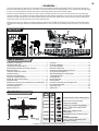
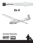
Archer Instruction Manual / Bedienungsanleitung Manuel d’utilisation / Manuale di Istruzioni EN NOTICE All instructions, warranties and other collateral documents are subject to change at the sole discretion of Horizon Hobby, Inc. For up-to-date product literature, visit www.horizonhobby.com and click on the support tab for this product. Meaning of Special Language: The following terms are used throughout the product literature to indicate various levels of potential harm when operating this product: NOTICE: Procedures, which if not properly followed, create a possibility of physical property damage AND little or no possibility of injury. CAUTION: Procedures, which if not properly followed, create the probability of physical property damage AND a possibility of serious injury. WARNING: Procedures, which if not properly followed, create the probability of property damage, collateral damage, and serious injury OR create a high probability of superficial injury. WARNING: Read the ENTIRE instruction manual to become familiar with the features of the product before operating. Failure to operate the product correctly can result in damage to the product, personal property and cause serious injury. This is a sophisticated hobby product. It must be operated with caution and common sense and requires some basic mechanical ability. Failure to operate this Product in a safe and responsible manner could result in injury or damage to the product or other property. This product is not intended for use by children without direct adult supervision. Do not attempt disassembly, use with incompatible components or augment product in any way without the approval of Horizon Hobby, Inc. This manual contains instructions for safety, operation and maintenance. It is essential to read and follow all the instructions and warnings in the manual, prior to assembly, setup or use, in order to operate correctly and avoid damage or serious injury. Age Recommendation: Not for children under 14 years. This is not a toy. Safety Precautions and Warnings As the user of this product, you are solely responsible for operating in a manner that does not endanger yourself and others or result in damage to the product or the property of others. • Always keep a safe distance in all directions around your model to avoid collisions or injury. This model is controlled by a radio signal subject to interference from many sources outside your control. Interference can cause momentary loss of control • Always operate your model in open spaces away from full-size vehicles, traffic and people. • Always carefully follow the directions and warnings for this and any optional support equipment (chargers, rechargeable battery packs, etc.). • Always keep all chemicals, small parts and anything electrical out of the reach of children. • Always avoid water exposure to all equipment not specifically designed and protected for this purpose. Moisture causes damage to electronics. • Never place any portion of the model in your mouth as it could cause serious injury or even death. • Never operate your model with low transmitter batteries. • Always keep aircraft in sight and under control. • Always use fully charged batteries. • Always keep transmitter powered on while aircraft is powered. • Always remove batteries before disassembly. • Always keep moving parts clean. • Always keep parts dry. • Always let parts cool after use before touching. • Always remove batteries after use. • Always ensure failsafe is properly set before flying. • Never operate aircraft with damaged wiring. • Never touch moving parts. Battery Warning The Battery Charger included with your aircraft is designed to safely balance and charge the Li-Po battery. CAUTION: All instructions and warnings must be followed exactly. Mishandling of Li-Po batteries can result in a fire, personal injury, and/or property damage. • By handling, charging or using the included Li-Po battery, you assume all risks associated with lithium batteries. • If at any time the battery begins to balloon or swell, discontinue use immediately. If charging or discharging, discontinue and disconnect. Continuing to use, charge or discharge a battery that is ballooning or swelling can result in fire. • Always store the battery at room temperature in a dry area for best results. • Always transport or temporarily store the battery in a temperature range of 40–120º F (5–49º C). Do not store the battery or aircraft in a car or direct sunlight. If stored in a hot car, the battery can be damaged or even catch fire. • Always charge batteries away from flammable materials. • Always inspect the battery before charging and never charge damaged batteries. • Always disconnect the battery after charging, and let the charger cool between charges. 2 • Always constantly monitor the temperature of the battery pack while charging. • ONLY USE A CHARGER SPECIFICALLY DESIGNED TO CHARGE LI-PO BATTERIES. Failure to charge the battery with a compatible charger may cause fire resulting in personal injury and/or property damage • Never discharge Li-Po cells to below 3V under load. • Never cover warning labels with hook and loop strips. • Never leave charging batteries unattended. • Never charge batteries outside recommended levels. • Never attempt to dismantle or alter the charger. • Never allow minors to charge battery packs. • Never charge batteries in extremely hot or cold places (recommended between 40–120° F or 5–49° C) or place in direct sunlight. EN – Introduction – As you’re about to find out, the compact size, scale good looks and no-nonsense flight characteristics of the ParkZone® Archer™ aircraft make it excellent company to have around almost anywhere. At home, on the road or on your lunch break, you’ll have no trouble finding the time or opportunity to fly. Assembly couldn’t be easier. In fact, you’ll probably have it together and ready for its maiden flight well before the battery has finished charging. If the Archer is the first sport plane you’ve flown since soloing a trainer, you’ll find the transition is an easy one. Like most trainers, it has tricycle landing gear and plenty of dihedral, so you should feel right at home during takeoffs and landings. About the only difference is in the shape of the wing. Unlike the flat-bottom airfoils on a lot of high-wing trainers, the semi-symmetrical airfoil makes the aircraft less likely to float and may require a touch more speed on landings. You’ll want to factor that into your approach profile as you prepare for that first landing. Whatever your experience level, though, you must take some time to read this manual. In addition to instructions for final assembly, you’ll find handy setup tips, important battery charging precautions and a helpful troubleshooting guide. It’s all here to make sure your first flight, and every one after it, is as successful as can be. Box Contents Includes Table of Contents Charging the Flight Battery ............................................................... 4 Low Voltage Cutoff (LVC) ................................................................... 4 Installing the Transmitter Batteries .................................................... 5 Understanding the Controls of the DX4e Transmitter ......................... 5 DX4e Range Check ........................................................................... 6 Transmitter and Receiver Binding...................................................... 7 Installing the Battery ......................................................................... 7 Arming the ESC and Receiver............................................................ 8 Installing the Horizontal Stabilizer ..................................................... 9 Control Horn and Servo Arm Settings ................................................ 9 Installing the Wing .......................................................................... 10 Control Surface Centering and Installing Clevises on Control Horns . 10 Installing the Landing Gear ............................................................. 11 Center of Gravity (CG) ..................................................................... 11 Control Direction Test ...................................................................... 12 Dual Rates ...................................................................................... 12 Flying Tips and Repairs ................................................................... 13 First Flight Preparation .................................................................... 13 Maintenance After Flying ................................................................ 13 Removing the Nose Gear Nose Gear Service ................................... 14 Service of Power Components ........................................................ 14 AMA National Model Aircraft Safety Code ........................................ 15 Troubleshooting Guide .................................................................... 16 Limited Warranty ............................................................................ 17 Contact Information ........................................................................ 17 FCC Information .............................................................................. 18 Compliance Information for the European Union .............................. 18 Parts Contact Information ............................................................... 67 Replacement Parts.......................................................................... 67 Optional Parts ................................................................................. 68 Specifications 25.6 inches (650mm) 36.8 inches (935mm) Installed Installed 370 Brushless Outrunner Motor, 1300Kv (PKZ6116) Installed Installed 10-Amp Pro Brushless ESC (EFLA1010) Installed Installed Installed Installed Included Included Included Included Weight: 16.4 oz (466 g) Needed to DX4e Complete Included (2) Aileron Servos (PKZ1081) (1) Rudder Servo (1) Elevator Servo (PKZ1080) Spektrum™ AR400 4-Channel DSM2®/DSMX® Aircraft Receiver Battery: 7.4V 2S 1300mAh 20C Li-Po (EFLB13002S20) Battery Charger: 2S DC Li-Po balancing charger (EFLC3125) Recommended Transmitter: Full-Range 4-Channel 2.4GHz with Spektrum™ DSM2®/DSMX® technology. To register your product online, visit www.parkzone.com 3 EN Charging the Flight Battery Your aircraft comes with a DC balancing charger and 2S Li-Po battery. You should only charge your battery with the included charger. Never leave the battery and charger unattended during the charge process. Failure to follow the instructions properly could result in a fire. When charging, ensure the battery is on a heat-resistant surface. Charge the flight battery while assembling the aircraft. Install the fully charged battery to perform control tests and binding. Charger Specifications • Input power: 10–14V • Charges 2-cell Li-Po packs with a minimum capacity of 1300mAh DC Li-Po Balancing Charger Features • Balances and charges 2-cell lithium polymer battery packs • LED charge status indicator • 12V accessory outlet power cord Purchase optional 12V adapters (HBZ6513 or HBZ4747) to power your charger more conveniently. 7.4V 2S 1300mAh 20C Li-Po (EFLB13002S20) • Maximum charge rate 1C (1.3 amps) The E-flite® 2S Li-Po battery pack features a balancing lead that allows you to safely charge your battery pack when used with the included Li-Po balancing charger. The Battery Charging Process 1. Charge only batteries that are cool to the touch and are not damaged. Look at the battery to make sure it is not damaged e.g., swollen, bent, broken or punctured. 2. Insert the charger into the appropriate power supply (12V accessory outlet). 3. Connect the balancing lead of the battery to the charger port. 4. The LED will flash during charging. 5. The LED will glow solid when the battery is fully charged. (Approximately 1 hour) 6. Always disconnect the battery from the charger immediately upon completion of charging. The LED will turn off. CAUTION: Overcharging a battery can cause a fire. CAUTION: Only use a charger specifically designed to charge a Li-Po battery. Failure to do so could result in fire causing injury or property damage. CAUTION: Never exceed the recommended charge rate. NOTICE: If using a battery other than the included Li-Po battery, refer to your battery manufacturer’s instructions for charging. Low Voltage Cutoff (LVC) When a Li-Po battery is discharged below 3V per cell, it will not hold a charge. The ESC protects the flight battery from over-discharge using Low Voltage Cutoff (LVC). Before the battery charge decreases too much, LVC removes power supplied to the motor. Power to the motor pulses, showing that some battery power is reserved for flight control and safe landing. Disconnect and remove the Li-Po battery from the aircraft after use to prevent trickle discharge. Charge your Li-Po battery to about half capacity before storage. During storage, make sure the battery charge does not fall below 3V per cell. LVC does not prevent the battery from over-discharge during storage. NOTICE: Repeated flying to LVC will damage the battery. When the motor pulses, land the aircraft immediately and recharge the flight battery. 4 EN Installing the Transmitter Batteries 1 2 3 Your Spektrum DX4e comes prebound to the aircraft. Remove the battery cover, install the four included batteries (noting proper polarity) and reinstall the battery cover. Low Battery Alarm When the battery voltage drops below 4.7 volts, an alarm sounds and the voltage LEDs flash. The batteries must be replaced immediately. If this happens while flying, land your aircraft as soon and as safely as possible. Understanding the Controls of the DX4e Transmitter KEY A B C D E F G H I J K L M N O P Q A Antenna B Handle Trainer/Bind Button (Modes 1/3 only) R Hi/Lo Rate Switch C For more information on the transmitter, go to http://www.horizonhobby.com/products/ dx4e-dsmx-4-channel-full-range-tx-onlymd2-4-SPMR4400 and click on the support tab for the Spektrum DX4e to download the instruction manual. Right Control Stick Trim Slider (for up/down on stick) Neck Strap Connection Q D Trim Slider (for left/right on stick) P O N M L E F G H K I J Mode Switch (1/3 or 2/4) Mix Switch (Elevon only) Servo Reverse Switches Power Switch (ON/OFF) Trim Slider (for left/right on stick) Trim Slider (for up/down on stick) Left Control Stick LEDs ACT/AUX Switch (Channel 5) R S T Trainer/Bind Button (Modes 2/4 only) T S Battery Cover Trainer Port * The diagram shows the transmitter controls for Mode 2 and Mode 1 transmitters. Trainer/Bind Button ((C) Mode 1 or (R) Mode 2) The Trainer/Bind Button is used during binding or when connecting a trainer cord (SPM6805) to the trainer port (T). For complete binding instructions, refer to the binding section in this manual. When using the trainer function, connect the trainer cord into the trainer port in both the master (instructor) and the slave (student) transmitters. The master transmitter must be powered ON and bound to the receiver. The slave transmitter must be powered OFF. Any time you press and hold the trainer button on the master, it will give control authority to the slave. Releasing the trainer button returns control to the master. IMPORTANT: The slave transmitter must always have the same reverse settings as the master. channels. In the lower, or “LO”, position, servo travel decreases to 70% on these channels. This switch lets you quickly change control rates from high for aggressive maneuvers to low for smooth, precise maneuvers. When learning to fly, use low rate. Mode Switch (I) This switch changes channel assignments to the control sticks. Always ensure the controls respond as desired before flying. A Mode 1 transmitter may be switched to Mode 3, while a Mode 2 transmitter may be switched to Mode 4. Mix Switch (J) This switch enables a mix for elevons on Delta wing aircraft. If needed, refer to the transmitter manual for more information. Hi/Lo Rate Switch (D) This switch supports high and low rate functions on aileron, elevator and rudder channels. In the upper, or “HI” position, servo travel is 100% on these 5 EN Servo Reversing Switches (K) These switches select the servo direction of each channel. Use your fingernail or a small screwdriver to change the switch position to normal (NOR) or reverse (REV) as needed to make transmitter controls operate the model as desired. Perform the Control Direction Test before flying. ACT/AUX Switch (Q) This switch activates a receiver channel (such as servos) connected through an AUX channel of the receiver. France RF Setting The DX4e has a France RF setting that complies with French regulations. The France RF setting should only be turned on when operating your transmitter in France outdoors. 1 To set France mode (Illustration 1 below): Push and hold the trainer button on the top of the transmitter while pushing and holding the two sticks as shown below, then power ON the transmitter. After hearing a series of descending beep tones (high to low), release the trainer switch and the sticks. The France setting is now turned on. Bind the transmitter to the receiver for the change to take effect. To set Standard mode (Illustration 2 below): Push and hold the trainer button on the top of the transmitter while pushing and holding the two sticks as shown below, then power ON the transmitter. After hearing a series of ascending beep tones (low to high), release the trainer switch and the sticks. The France setting is turned off. 2 DX4e Range Check Placing the transmitter in RANGE CHECK mode reduces the output power, allowing a range check. DX4e Transmitter Range Check Process Before performing the range check, ensure the correct failsafe stick positions are established. 1. With the system powered on and the model restrained on the ground*, stand 90ft/28m away from the model. 2. Face the model with the transmitter in your normal flying position. 3. Push and hold the trainer button while toggling the Hi/Lo Rate Switch four times. 4. The LEDs will flash and the alarm will sound. The system is in range check mode. IMPORTANT: You must hold the trainer button during the entire range check process. Releasing the button switch will exit the range check mode. You should have total control of the model with the trainer button held at 90ft/28m meters. *In some aircraft, when the model is placed on the ground, the antenna(s) can be within inches of the ground. Close proximity of the antenna(s) to the ground can reduce the effectiveness of the range check. This is called pulling. If you experience issues during the range check, restrain the model on a nonconductive stand or table up to 2ft (60cm) above the ground. Then range check the system again. If control issues exist, contact the appropriate Product Support Department for assistance, or visit the Spektrum website for more information. 6 ers (90 28 met feet) EN Transmitter and Receiver Binding Binding is the process of programming the receiver to recognize the GUID (Globally Unique Identifier) code of a single specific transmitter. You need to ‘bind’ your chosen Spektrum™ DSM2®/DSMX® technology equipped aircraft transmitter to the receiver for proper operation (Please visit www.bindnfly.com for a complete list of compatible transmitters). CAUTION: When using a Futaba® transmitter with a Spektrum DSM® module, you must reverse the throttle channel and rebind. Refer to your Spektrum module manual for binding and failsafe instructions. Refer to your Futaba transmitter manual for instructions on reversing the throttle channel. Binding Procedure Reference Table (RTF Version: Your Spektrum DX4e comes prebound to the aircraft.) 1. Read the transmitter instructions for binding to a receiver (location of transmitter’s Bind control). 2. Make sure the transmitter is powered OFF. 3. Move the transmitter controls to neutral (flight controls: rudder, elevators and ailerons) or to low positions (throttle, throttle trim).* 4. Install a bind plug in the receiver bind port. 5. Connect the flight battery to the ESC. The ESC will produce a series of sounds. One long tone, then two short tones confirm that the LVC is set for the ESC. 6. The receiver LED will begin to flash rapidly. 7. Power ON the transmitter while holding the transmitter bind button or switch. Refer to your transmitter’s manual for binding button or switch instructions. For the DX4e, release the trainer/bind button once the LEDs flash and a series of beeps sound. Within a few seconds, the system should connect. 8. When the receiver binds to the transmitter, the light on the receiver will turn solid and the ESC will produce a series of three ascending tones. The tones indicate the ESC is armed, provided the throttle stick and throttle trim are low enough to trigger arming. 9. Remove the bind plug from the bind port. BIND PLUG 10. Safely store the bind plug (some owners attach the bind plug to their transmitter using two-part loops and clips). 11. The receiver should retain the binding instructions received from the transmitter until another binding is done. * The throttle will not arm if the transmitter’s throttle control is not put at the lowest position. If you encounter problems, follow the binding instructions and refer to the transmitter troubleshooting guide for other instructions. If needed, contact the appropriate Horizon Product Support office. Installing the Battery A 1. Push the antenna (A) into the fuselage, releasing the canopy latch. 2. Lift the back of the canopy and pull backwards to remove the canopy. 3. Install the fully charged battery (B) in the battery compartment. See the Adjusting the Center of Gravity instructions for more information. 4. Make sure the flight battery is secured using the hook and loop strap (C). 5. Reinstall the canopy. Push the rear of the canopy securely to ensure the latch is fully engaged. B C 7 EN Arming the ESC and Receiver Arming the ESC also occurs after binding as previously described, but subsequent connection of a flight battery requires the steps below. 1 CAUTION: Always keep hands away from the propeller. When armed, the motor will turn the propeller in response to any throttle movement. CAUTION: Always disconnect the Li-Po battery from the aircraft receiver when not flying to avoid over-discharging the battery. Batteries discharged to a voltage lower than the lowest approved voltage may become damaged, resulting in loss of performance and potential fire when batteries are charged. 1. Power ON the transmitter and lower the throttle and throttle trim to their lowest settings. 2 DO NOT connect the battery while the throttle stick is at full or the ESC will go into programming mode. If a musical tone sounds after 5 seconds, immediately disconnect the battery, then lower the throttle. 2. Remove the canopy and install the fully charged battery in the battery compartment using the hook and loop strip, then connect the battery to the ESC. 3. When power is applied to the ESC: 1) The ESC will sound two tones to indicate that LVC is properly set. 2) An LED will light on the receiver. 8 3 EN Installing the Horizontal Stabilizer A 1. Connect the linkage (A) to the outermost hole on the elevator control horn (B). You will need to rotate the horizontal stabilizer to attach the z-bend of the pushrod to the control horn on the elevator. B Tip: Move the elevator servo arm to full travel. This moves the pushrod rearward to give the most room to install the horizontal stabilizer. Make sure to center the servo again before flight. 2. Slide the horizontal stabilizer into the slot and align the two pins at the front of the horizontal stabilizer to the plastic stabilizer mount on the fuselage. 3. Turn the rudder to the right or left and secure the horizontal tail to the fuselage using a screw (C). When needed, disassemble in reverse order. C Control Horn and Servo Arm Settings Fly the model at factory settings before making changes. For pilots who wish to fly the model with more or less control throw, adjust the position of the linkages on the servo arms and control horns for increased travel. Always ensure the steering linkage on the rudder servo arm is correctly adjusted so the model steers straight when the rudder control is at neutral. Horns Arms Elevator More control throw Less control throw Rudder Nose Gear Steering Ailerons 9 EN Installing the Wing 1. Remove the canopy from the fuselage. 2. Turn the wing and fuselage over so their bottom sides face up. 3. Place the wing’s aileron servo connectors (A) into the hole in the fuselage. 4. Slide the two guide pins (B) at the rear of the wing into the two holes in the fuselage. 5. Align and attach the wing to the fuselage using two screws (C). B 6. Inside the fuselage, connect both aileron servo connectors to the aileron Y-harness connectors. The left and right aileron servos can be connected to either side of the Y-harness. When needed, disassemble in reverse order. CAUTION: DO NOT crush or otherwise damage wiring when attaching the wing to the fuselage. A Control Surface Centering and Installing Clevises on Control Horns Tip: Turn the clevis on the linkage to change the length of the linkage between the servo arm and the control horn. • Pull the tube from the clevis to the linkage. • Carefully spread the clevis, then insert the clevis pin into the desired hole in the control horn. • Move the tube to hold the clevis on the control horn. After binding a transmitter to the model receiver, set the trims and sub-trims to 0, then adjust the clevises to center the control surfaces. 1. 4. 2. 5. 3. 6. 10 C EN Installing the Landing Gear 1. Turn the fuselage so that the bottom of the wing faces up. 2. Install the main landing gear by inserting the main gear struts (A) into the corresponding gear plate hole located on each wing. A 3. Carefully turn each strut in the gear plate until the horizontal section of the strut snaps into place. When needed, disassemble in reverse order. Center of Gravity (CG) The CG location is 40mm back from the leading edge of the wing. Install the flight battery all the way to the front of the battery compartment. Make sure the flight battery is secured using the hook and loop strap. It is easiest to balance the Archer with the aircraft inverted. 40mm 1.60 inches back from the leading edge of the wing. 11 EN Control Direction Test Move the controls on the transmitter to make sure the aircraft control surfaces move correctly and in the proper direction. After performing the Control Test, correctly set the failsafe. Make sure the transmitter controls are at neutral and the throttle and throttle trim are in the low position, then rebind the model to your transmitter. If the receiver loses its link to the transmitter, the failsafe will drive the servos to these settings made at binding. Rudder Aileron Elevator Transmitter Command Aircraft Reaction Up Elevator Command Down Elevator Command Stick Right Stick Left Stick Right Stick Left Dual Rates Your DSM2/DSMX full range transmitter features dual rates to help you select the amount of travel that you want from the control surfaces. 12 High Rate Low Rate Aileron 12mm up/down 9mm up/down Elevator 9mm up/down 7mm up/down Rudder 12mm left/right 8mm left/right EN Flying Tips and Repairs Consult local laws and ordinances before choosing a flying location. Range Check your Radio System After final assembly, range check the radio system with the aircraft. Refer to the DX4e “Range Check” section found earlier in the manual for RTF. Or refer to your specific transmitter instruction manual for BNF. NOTICE: If a crash is imminent, reduce the throttle and trim fully. Failure to do so could result in extra damage to the airframe, as well as damage to the ESC and motor. nd Wi Flying Fly in this area Always choose a wide-open space for flying your aircraft. It is ideal for you to fly at a sanctioned flying field. If you are not flying at an approved site, always avoid flying near houses, trees, wires and buildings. You should also be careful to avoid flying in areas where there are many people, such as busy parks, schoolyards, or soccer fields. 600 feet (182 Always decrease throttle at propeller strike. .8 m ) Stand here Takeoff Start the takeoff using rudder to keep the aircraft straight. As the aircraft reaches flying speed, apply a slight amount of up elevator and the aircraft will fly off the ground. Avoid forcing the aircraft into the air. Climb to check trim. Once the trim is adjusted, you can begin to explore the flight envelope of the aircraft. Landing Flight times of 11 minutes or more are achievable if using proper throttle management. For your first flights, set your transmitter timer or a stopwatch to 9 minutes. Adjust your timer for longer or shorter flights once you have flown the model. When the motor pulses, land the aircraft immediately and recharge the flight battery. It is not recommended to fly the battery to LVC. NOTICE: Repeated flying to the LVC will damage your battery. To land the aircraft, fly to about a foot off the ground. Reduce power and start applying up elevator to flare the aircraft. Touch down on the main wheels first. Due to the angle the aircraft sits, it is possible to land nosewheel first, causing a bounce. If the aircraft bounces back into the air, apply power and go around for another landing. Once on the ground, gently steer with the rudder until the aircraft has slowed. NOTICE: Crash damage is not covered under warranty. NOTICE: When you are finished flying, never keep the aircraft in the sun. Do not store the aircraft in a hot, enclosed area such as a car. Doing so can damage the foam. Repairs Thanks to the Z-Foam™ construction of this aircraft, repairs to the foam can be made using virtually any adhesive (hot glue, regular CA, epoxy, etc). When parts are not repairable, see the Replacement Parts List for ordering by item number. For a listing of all replacement and optional parts, refer to the list at the end of this manual. NOTICE: Use of CA accelerant on your aircraft can damage paint. DO NOT handle the aircraft until accelerant fully dries. First Flight Preparation 1. 2. 3. 4. 5. 6. Read this instruction manual thoroughly. Remove and inspect the contents. Charge the flight battery. Fully assemble the model. Install the flight battery in the aircraft (once it has been fully charged). Bind the aircraft to your transmitter. (BNF only) 7. Make sure the linkages move freely. 8. Perform the Control Direction Test with the transmitter. 9. Adjust the flight controls and transmitter. 10. Perform a radio system Range Check. 11. Find a safe and open area. 12. Plan flight for flying field conditions. Maintenance After Flying 1. Disconnect the flight battery from the ESC (Required for Safety and battery life). 2. Power OFF the transmitter. 3. Remove the flight battery from the aircraft. 4. Recharge the flight battery. 5. Repair or replace all damaged parts. 6. Store the flight battery apart from the aircraft and monitor the battery charge. 7. Make note of the flight conditions and flight plan results, planning for future flights. 13 EN Removing the Nose Gear Nose Gear Service Hard landings may damage the nose gear. Replace damaged parts as needed. CAUTION: DO NOT handle the propeller while the flight battery is connected to the ESC. Personal injury could result. E C 1. Remove the canopy from the model. D G 2. Disconnect the flight battery from the model. 3. Disconnect the steering linkage from the rudder servo arm. 4. Remove the propeller and cowling from the model (as shown in the “Service of Power Components” section of this manual). F A 5. Loosen the nose gear screw (A) and remove the strut (B). 6. Remove the four screws (C) and steering arm retainer (D) from the firewall. 7. Pull the steering linkage (E) forward and remove the Z-bend end (F) of the linkage from the steering arm (G). B Reassemble in reverse order. NOTICE: Always make sure the steering linkage is adjusted correctly to ensure the model steers straight when the rudder control is at neutral. Service of Power Components Disassembly Assembly CAUTION: Always disconnect the flight battery from the model before removing the propeller. 1. Remove the screw (A) and spinner (B) from the collet (G). 2. Remove the spinner nut (C), propeller (D), spinner backplate (E), backplate (F) and collet (G) from the motor shaft (H). You will need a tool to turn the spinner nut. 3. Remove the three screws (I) from the cowling (J). Carefully remove the cowling from the fuselage. Paint may keep the cowling attached to the fuselage. 4. Remove the four screws (K) from the motor mount (L) and the fuselage. 5. Disconnect the motor wires from the ESC wires. 6. Remove the four screws (M) and motor (N) from the motor mount. A B C D E F Assemble in reverse order. • Correctly align and connect the motor wire colors with the ESC wires. • The propeller size numbers (8.25 x 5.5) must face out from the motor for correct propeller operation. • A tool is required to tighten the spinner nut on the collet. • Ensure the spinner is fully connected to the spinner back plate for safe operation. G J H N K L M I Not all wiring shown. 14 EN AMA National Model Aircraft Safety Code Effective January 1, 2011 A. GENERAL A model aircraft is a non-human-carrying aircraft capable of sustained flight in the atmosphere. It may not exceed limitations of this code and is intended exclusively for sport, recreation and/or competition. All model flights must be conducted in accordance with this safety code and any additional rules specific to the flying site. 1. Model aircraft will not be flown: (a) In a careless or reckless manner. (b) At a location where model aircraft activities are prohibited. 2. Model aircraft pilots will: (a) Yield the right of way to all man carrying aircraft. (b) See and avoid all aircraft and a spotter must be used when appropriate. (AMA Document #540-D-See and Avoid Guidance.) (c) Not fly higher than approximately 400 feet above ground level within three (3) miles of an airport, without notifying the airport operator. (d) Not interfere with operations and traffic patterns at any airport, heliport or seaplane base except where there is a mixed use agreement. (e) Not exceed a takeoff weight, including fuel, of 55 pounds unless in compliance with the AMA Large Model Aircraft program. (AMA Document 520-A) (f) Ensure the aircraft is identified with the name and address or AMA number of the owner on the inside or affixed to the outside of the model aircraft. (This does not apply to model aircraft flown indoors). (g) Not operate aircraft with metal-blade propellers or with gaseous boosts except for helicopters operated under the provisions of AMA Document #555. (h) Not operate model aircraft while under the influence of alcohol or while using any drug which could adversely affect the pilot’s ability to safely control the model. (i) Not operate model aircraft carrying pyrotechnic devices which explode or burn, or any device which propels a projectile or drops any object that creates a hazard to persons or property. Exceptions: • Free Flight fuses or devices that burn producing smoke and are securely attached to the model aircraft during flight. • Rocket motors (using solid propellant) up to a G-series size may be used provided they remain attached to the model during flight. Model rockets may be flown in accordance with the National Model Rocketry Safety Code but may not be launched from model aircraft. • Officially designated AMA Air Show Teams (AST) are authorized to use devices and practices as defined within the Team AMA Program Document (AMA Document #718). (j) Not operate a turbine-powered aircraft, unless in compliance with the AMA turbine regulations. (AMA Document #510-A). 3. Model aircraft will not be flown in AMA sanctioned events, air shows or model demonstrations unless: (a) The aircraft, control system and pilot skills have successfully demonstrated all maneuvers intended or anticipated prior to the specific event. (b) An inexperienced pilot is assisted by an experienced pilot. 4. When and where required by rule, helmets must be properly worn and fastened. They must be OSHA, DOT, ANSI, SNELL or NOCSAE approved or comply with comparable standards. B. RADIO CONTROL 1. All pilots shall avoid flying directly over unprotected people, vessels, vehicles or structures and shall avoid endangerment of life and property of others. 2. A successful radio equipment ground-range check in accordance with manufacturer’s recommendations will be completed before the first flight of a new or repaired model aircraft. 3. At all flying sites a safety line(s) must be established in front of which all flying takes place (AMA Document #706-Recommended Field Layout): (a) Only personnel associated with flying the model aircraft are allowed at or in front of the safety line. (b) At air shows or demonstrations, a straight safety line must be established. (c) An area away from the safety line must be maintained for spectators. (d) Intentional flying behind the safety line is prohibited. 4. RC model aircraft must use the radio-control frequencies currently allowed by the Federal Communications Commission (FCC). Only individuals properly licensed by the FCC are authorized to operate equipment on Amateur Band frequencies. 5. RC model aircraft will not operate within three (3) miles of any pre-existing flying site without a frequency-management agreement (AMA Documents #922-Testing for RF Interference; #923- Frequency Management Agreement) 6. With the exception of events flown under official AMA Competition Regulations, excluding takeoff and landing, no powered model may be flown outdoors closer than 25 feet to any individual, except for the pilot and the pilot’s helper(s) located at the flight line. 7. Under no circumstances may a pilot or other person touch a model aircraft in flight while it is still under power, except to divert it from striking an individual. This does not apply to model aircraft flown indoors. 8. RC night flying requires a lighting system providing the pilot with a clear view of the model’s attitude and orientation at all times. 9. The pilot of a RC model aircraft shall: (a) Maintain control during the entire flight, maintaining visual contact without enhancement other than by corrective lenses prescribed for the pilot. (b) Fly using the assistance of a camera or First-Person View (FPV) only in accordance with the procedures outlined in AMA Document #550. Please see your local or regional modeling association’s guidelines for proper, safe operation of your model aircraft. 15 EN Troubleshooting Guide Problem Aircraft will not respond to throttle but responds to other controls Extra propeller noise or extra vibration Reduced flight time or aircraft underpowered Aircraft will not Bind (during binding) to transmitter Aircraft will not connect (after binding) to transmitter Possible Cause Solution Throttle not at idle and/or throttle trim too high Reset controls with throttle stick and throttle trim at lowest setting Throttle servo travel is lower than 100% Make sure throttle servo travel is 100% or greater Throttle channel is reversed Reverse throttle channel on transmitter Motor disconnected from ESC Make sure motor is connected to the ESC Damaged propeller and spinner, collet or motor Replace damaged parts Propeller is out of balance Balance or replace propeller Prop nut is too loose Tighten the prop nut Spinner is not tight or fully seated in place Tighten the spinner or remove the spinner and turn it 180 degrees. Flight battery charge is low Completely recharge flight battery Propeller installed backwards Install propeller with numbers facing forward Flight battery damaged Replace flight battery and follow flight battery instructions Flight conditions may be too cold Make sure battery is warm before use Battery C rating is too low Replace battery or use battery with correct C rating Transmitter too near aircraft during binding process Move powered transmitter a few feet from aircraft, disconnect and reconnect flight battery to aircraft Aircraft or transmitter is too close to large metal object, wireless source or another transmitter Move aircraft and transmitter to another location and attempt binding again The bind plug is not installed correctly in the bind port Install bind plug in bind port and bind the aircraft to the transmitter Flight battery/Transmitter battery charge is too low Replace/recharge batteries Bind switch or button not held long enough during bind process Power off transmitter and repeat bind process. Hold transmitter bind button or switch until receiver is bound Transmitter too near aircraft during connecting process Move powered transmitter a few feet from aircraft, disconnect and reconnect flight battery to aircraft Aircraft or transmitter is too close to large metal object, wireless source or another transmitter Move aircraft and transmitter to another location and attempt connecting again Bind plug left installed in bind port Rebind transmitter to the aircraft and remove the bind plug before cycling power Aircraft bound to different model memory (ModelMatchTM radios only) Select correct model memory on transmitter Flight battery/Transmitter battery charge is too low Replace/recharge batteries Transmitter may have been bound using different DSM protocol Bind aircraft to transmitter Control surface does Control surface, control horn, linkage or servo damage not move Wire damaged or connections loose Replace or repair damaged parts and adjust controls Do a check of wires and connections, connect or replace as needed Transmitter is not bound correctly or the incorrect model was selected Re-bind or select correct model in transmitter Flight battery charge is low Fully recharge flight battery BEC (Battery Elimination Circuit) of the ESC is damaged Replace ESC Controls reversed Transmitter settings are reversed Perform the Control Direction Test and adjust the controls on transmitter appropriately Motor power pulses then motor loses power ESC uses default soft Low Voltage Cutoff (LVC) Recharge flight battery or replace battery that is no longer performing Weather conditions might be too cold Postpone flight until weather is warmer Battery is old, worn out, or damaged Replace battery Battery C rating might be too small Use recommended battery 16 EN Limited Warranty What this Warranty Covers Horizon Hobby, Inc. (“Horizon”) warrants to the original purchaser that the product purchased (the “Product”) will be free from defects in materials and workmanship at the date of purchase. What is Not Covered This warranty is not transferable and does not cover (i) cosmetic damage, (ii) damage due to acts of God, accident, misuse, abuse, negligence, commercial use, or due to improper use, installation, operation or maintenance, (iii) modification of or to any part of the Product, (iv) attempted service by anyone other than a Horizon Hobby authorized service center, (v) Product not purchased from an authorized Horizon dealer, or (vi) Product not compliant with applicable technical regulations. OTHER THAN THE EXPRESS WARRANTY ABOVE, HORIZON MAKES NO OTHER WARRANTY OR REPRESENTATION, AND HEREBY DISCLAIMS ANY AND ALL IMPLIED WARRANTIES, INCLUDING, WITHOUT LIMITATION, THE IMPLIED WARRANTIES OF NON-INFRINGEMENT, MERCHANTABILITY AND FITNESS FOR A PARTICULAR PURPOSE. THE PURCHASER ACKNOWLEDGES THAT THEY ALONE HAVE DETERMINED THAT THE PRODUCT WILL SUITABLY MEET THE REQUIREMENTS OF THE PURCHASER’S INTENDED USE. Purchaser’s Remedy Horizon’s sole obligation and purchaser’s sole and exclusive remedy shall be that Horizon will, at its option, either (i) service, or (ii) replace, any Product determined by Horizon to be defective. Horizon reserves the right to inspect any and all Product(s) involved in a warranty claim. Service or replacement decisions are at the sole discretion of Horizon. Proof of purchase is required for all warranty claims. SERVICE OR REPLACEMENT AS PROVIDED UNDER THIS WARRANTY IS THE PURCHASER’S SOLE AND EXCLUSIVE REMEDY. Limitation of Liability HORIZON SHALL NOT BE LIABLE FOR SPECIAL, INDIRECT, INCIDENTAL OR CONSEQUENTIAL DAMAGES, LOSS OF PROFITS OR PRODUCTION OR COMMERCIAL LOSS IN ANY WAY, REGARDLESS OF WHETHER SUCH CLAIM IS BASED IN CONTRACT, WARRANTY, TORT, NEGLIGENCE, STRICT LIABILITY OR ANY OTHER THEORY OF LIABILITY, EVEN IF HORIZON HAS BEEN ADVISED OF THE POSSIBILITY OF SUCH DAMAGES. Further, in no event shall the liability of Horizon exceed the individual price of the Product on which liability is asserted. As Horizon has no control over use, setup, final assembly, modification or misuse, no liability shall be assumed nor accepted for any resulting damage or injury. By the act of use, setup or assembly, the user accepts all resulting liability. If you as the purchaser or user are not prepared to accept the liability associated with the use of the Product, purchaser is advised to return the Product immediately in new and unused condition to the place of purchase. Law These terms are governed by Illinois law (without regard to conflict of law principals). This warranty gives you specific legal rights, and you may also have other rights which vary from state to state. Horizon reserves the right to change or modify this warranty at any time without notice. WARRANTY SERVICES Questions, Assistance, and Services Your local hobby store and/or place of purchase cannot provide warranty support or service. Once assembly, setup or use of the Product has been started, you must contact your local distributor or Horizon directly. This will enable Horizon to better answer your questions and service you in the event that you may need any assistance. For questions or assistance, please visit our website at www.horizonhobby.com, submit a Product Support Inquiry, or call 877.504.0233 toll free to speak to a Product Support representative. Inspection or Services If this Product needs to be inspected or serviced and is compliant in the country you live and use the Product in, please use the Horizon Online Service Request submission process found on our website or call Horizon to obtain a Return Merchandise Authorization (RMA) number. Pack the Product securely using a shipping carton. Please note that original boxes may be included, but are not designed to withstand the rigors of shipping without additional protection. Ship via a carrier that provides tracking and insurance for lost or damaged parcels, as Horizon is not responsible for merchandise until it arrives and is accepted at our facility. An Online Service Request is available at http:// www.horizonhobby.com/content/_service-center_render-service-center. If you do not have internet access, please contact Horizon Product Support to obtain a RMA number along with instructions for submitting your product for service. When calling Horizon, you will be asked to provide your complete name, street address, email address and phone number where you can be reached during business hours. When sending product into Horizon, please include your RMA number, a list of the included items, and a brief summary of the problem. A copy of your original sales receipt must be included for warranty consideration. Be sure your name, address, and RMA number are clearly written on the outside of the shipping carton. NOTICE: Do not ship LiPo batteries to Horizon. If you have any issue with a LiPo battery, please contact the appropriate Horizon Product Support office. Warranty Requirements For Warranty consideration, you must include your original sales receipt verifying the proof-of-purchase date. Provided warranty conditions have been met, your Product will be serviced or replaced free of charge. Service or replacement decisions are at the sole discretion of Horizon. Non-Warranty Service Should your service not be covered by warranty, service will be completed and payment will be required without notification or estimate of the expense unless the expense exceeds 50% of the retail purchase cost. By submitting the item for service you are agreeing to payment of the service without notification. Service estimates are available upon request. You must include this request with your item submitted for service. Non-warranty service estimates will be billed a minimum of ½ hour of labor. In addition you will be billed for return freight. Horizon accepts money orders and cashier’s checks, as well as Visa, MasterCard, American Express, and Discover cards. By submitting any item to Horizon for service, you are agreeing to Horizon’s Terms and Conditions found on our website http://www.horizonhobby.com/ content/_service-center_render-service-center. NOTICE: Horizon service is limited to Product compliant in the country of use and ownership. If non-compliant product is received by Horizon for service, it will be returned unserviced at the sole expense of the purchaser. Contact Information Country of Purchase Horizon Hobby Address Phone Number/Email Address Horizon Service Center (Electronics and engines) 4105 Fieldstone Rd Champaign, Illinois 61822 USA 877-504-0233 Online Repair Request: visit www.horizonhobby.com/service Horizon Product Support (All other products) 4105 Fieldstone Rd Champaign, Illinois 61822 USA 877-504-0233 [email protected] United Kingdom Horizon Hobby Limited Units 1-4 Ployters Rd Staple Tye Harlow, Essex CM18 7NS, United Kingdom +44 (0) 1279 641 097 [email protected] Germany Horizon Technischer Service Christian-Junge-Straße 1 25337 Elmshorn, Germany +49 (0) 4121 2655 100 [email protected] France Horizon Hobby SAS 11 Rue Georges Charpak 77127 Lieusaint, France +33 (0) 1 60 18 34 90 [email protected] China Horizon Hobby – China Room 506, No. 97 Changshou Rd. Shanghai, China, 200060 +86 (021) 5180 9868 [email protected] United States of America 17 EN FCC Information Operation is subject to the following two conditions: (1) This device may not cause harmful interference, and (2) this device must accept any interference received, including interference that may cause undesired operation. CAUTION: Changes or modifications not expressly approved by the party responsible for compliance could void the user’s authority to operate the equipment. Antenna Separation Distance When operating your transmitter, please be sure to maintain a separation distance of at least 5 cm between your body (excluding fingers, hands, wrists, ankles and feet) and the antenna to meet RF exposure safety requirements as determined by FCC regulations. This product contains a radio transmitter with wireless technology which has been tested and found to be compliant with the applicable regulations governing a radio transmitter in the 2.400GHz to 2.4835GHz frequency range. This illustration show the approximate 5 cm RF exposure area and typical hand placement when operating your transmitter. Compliance Information for the European Union AT ES LT RO BE FI LU SE BG FR LV SI CZ CY DE GR HU IE MT NL PL SK UK DK IT PT Declaration of Conformity Declaration of Conformity (in accordance with ISO/IEC 17050-1) (in accordance with ISO/IEC 17050-1) No. HH20120101401 Product(s): Item Number(s): Equipment class: No. HH2012101402 PKZ Archer RTF PKZ6100, PKZ6100M1 2 The object of declaration described above is in conformity with the requirements of the specifications listed below, following the provisions of the European R&TTE directive 1999/5/EC, EMC Directive 2004/108/EC and LVD Directive 2006/95/EC: Product(s): Item Number(s): Equipment class: PKZ Archer BNF PKZ6180 1 The object of declaration described above is in conformity with the requirements of the specifications listed below, following the provisions of the European R&TTE directive 1999/5/EC, EMC Directive 2004/108/EC and LVD Directive 2006/95/EC: EN 300-328 V1.7.1: 2006 EN 301 489-1 V1.7.1: 2006 EN 301 489-17 V1.3.2: 2008 EN 301 489-1 V1.7.1: 2006 EN 301 489-17 V1.3.2: 2008 EN60950-1:2006+A11:2009+A1:2010+A12: 2011 EN60950-1:2006+A11:2009+A1:2010+A12: 2011 EN55022:2010 + AC:2011 EN55024:2010 EN55022:2010 + AC:2011 EN55024:2010 Signed for and on behalf of: Horizon Hobby, Inc. Steven A. Hall Champaign, IL USA Executive Vice President and Chief Operating Officer Oct 14, 2012 International Operations and Risk Management Horizon Hobby, Inc. Signed for and on behalf of: Horizon Hobby, Inc. Champaign, IL USA Steven A. Hall Oct 14, 2012 Executive Vice President and Chief Operating Officer International Operations and Risk Management Horizon Hobby, Inc. Instructions for disposal of WEEE by users in the European Union This product must not be disposed of with other waste. Instead, it is the user’s responsibility to dispose of their waste equipment by handing it over to a designated collections point for the recycling of waste electrical and electronic equipment. The separate collection and recycling of your waste equipment at the time of disposal will help to conserve natural resources and ensure that it is recycled in a manner that protects human health and the environment. For more information about where you can drop off your waste equipment for recycling, please contact your local city office, your household waste disposal service or where you purchased the product. 18 Parts Contact Information • Kontaktinformationen für Ersatzteile • Coordonnées pour obtenir des pièces détachées • Recapiti per i ricambi Country of Purchase Horizon Hobby Address Phone Number/Email Address United States of America Sales 4105 Fieldstone Rd Champaign, Illinois 61822 USA 800-338-4639 [email protected] United Kingdom Horizon Hobby Limited Units 1-4 Ployters Rd Staple Tye Harlow, Essex CM18 7NS, United Kingdom +44 (0) 1279 641 097 [email protected] Germany Horizon Hobby GmbH Christian-Junge-Straße 1 25337 Elmshorn, Germany +49 (0) 4121 2655 100 [email protected] France Horizon Hobby SAS 11 Rue Georges Charpak 77127 Lieusaint, France +33 (0) 1 60 18 34 90 [email protected] China Horizon Hobby – China Room 506, No. 97 Changshou Rd. Shanghai, China, 200060 +86 (021) 5180 9868 [email protected] Replacement Parts • Ersatzteile • Pièces de rechange • Pezzi di ricambio Part # | Nummer Numéro | Codice Description Beschreibung Description Descrizione PKZ6102 Decal Sheet: Archer Parkzone Archer: Derkorbogen Planche de décalcomanies: Archer Foglio con decalcomanie: Archer PKZ6103 Painted Pilot: Archer Parkzone Archer: Pilot lackiert Pilote peint: Archer Pilota verniciato: Archer PKZ6104 Canopy and Pilot: Archer Parkzone Archer: Kabinenhaube u. Pilot PKZ6106 Landing Gear Set: Archer Parkzone Archer: Fahrwerk-Set Set del carrello di atterraggio: Archer PKZ6111 Prop Adapter: Archer Parkzone Archer: Propelleradapter Verrière avec pilote: Archer Jeu de train d'atterrissage principal : Archer Adaptateur d’hélice: Archer PKZ6114 Firewall: Archer Parkzone Archer: Brandschott Cloison pare feu: Archer Ordinata motore: Archer PKZ6116 370 BL motor, 1300Kv Parkzone Archer: 370 BL Motor, 1300Kv Moteur 370BL, 1300Kv 370 BL motore, 1300Kv PKZ6118 Motor Shaft: metal 370 Outrunner Parkzone 370 Aussenläufer: Motorwelle Axe moteur 370BL Albero motore per 370 cassa rotante PKZ6120 Painted Wing: Archer Parkzone Archer: Tragfläche lackiert Aile peinte: Archer Ala verniciata: Archer PKZ6122 Pushrod Set: Archer Parkzone Archer: Schubstangen-Set Jeu de tiges: Archer Set asta di spinta: Archer PKZ6124 Vertical Stab: Archer Parkzone Archer: Höhenruder Dérive: Archer Impennaggio verticale: Archer PKZ6125 PKZ6126 PKZ6128 Horizontal Stab: Archer Parkzone Archer: Höhenleitwerk Stabilisateur horizontal: Archer Stabilizzatore orizzontale: Archer Cowl: Archer Parkzone Archer: Motorhaube Capotage : Archer Cappuccio: Archer Motor Mount: Archer Parkzone Archer:Motorträger Support moteur : Archer Supporto del motore: Archer PKZ6167 PKZ1080 PKZ1081 Painted Bare Fuse: Archer Parkzone Archer: Rumpf ohne Einbauten Fuselage nu peint: Archer Fusoliera nuda verniciata: Archer SV80 Short Lead Servo Parkzone SV80 Servo Servo de dérive SV80 SV80 servo con cavo corto SV80 Long Lead 3-Wire Servo Parkzone SV80 Servo mit langem Kabel EFLA1010 10-Amp Pro Brushless ESC 10A Pro Regler EFLAEC207 EC2 BATT to JST Female,15mm 20AWG AR400 4-Channel DSM2/DSMX Aircraft Receiver EC2 Akku auf JST Buchse, 15mm, 20 AWG Spektrum AR400 4-Channel DSMX Flugzeug Empfänger SV80 servo a 3 fi li a terminale lungo Controllo elettronico di velocità (ESC) per 10 Amp Pro Brushless Adaptateur prise EC2 vers JST femelle, EC2 BATT a JST femmina,15mm longueur 15mm 20AWG Récepteur AR400 4 voies DSM2/DSMX AR400 4-canali DSM2/DSMX ricevitore 2S 7.4V 20C Li-Po, 13 EFLB13002S20 1300mAh AWG EC2 Battery Propeller 8.25 x 5.5 PKZ1022 2-Cell DC Balancing Li-Po EFLC3125 Charger 1300mAh 2S 7.4V 20C Li-Po, 13 AWG EC2 Akku Propeller 8.25 x 5.5 Batterie LI-Po 7.4V 2S 1300mA 20C, prise EC2 Hélice 8.25 x 5.5 2S DC Balancing Ladegerät Chargeur équilibreur LI-Po DC 2S SPMAR400 Capottina e pilota: Archer Adattatore elica: Archer Servo 3 câbles grande longueur SV80 Contrôleur brushless pro 10A Batteria 1300mAh 2S 7.4V 20C Li-Po, 13 AWG EC2 Elica 8.25 x 5.5 Caricabatterie per 2 celle LiPo con bilanciatore 67 Optional Parts • Optionale Bauteile • Pièces optionnelles • Pezzi opzionali Part # | Nummer Numéro | Codice Description Beschreibung Description Descrizione SPM6805 Trainer Cord: ALL SPM Cordon écolage : Toutes les SPM Cavo trainer EFLA250 Park Flyer Tool Assortment, 5 pc Spektrum Trainerkabel E-flite Park Flyer Werkzeugsortiment; 5 teilig Assortiment d'outils park flyer, 5pc EFLAEC202 EC2 Battery Connector, Female (2) E-flite EC2 Akkubuchse (2) Prise EC2 femelle (2pc) EFLAEC203 EC2 Device/Battery Connector, Male/Female E-flite EC2 Stecker / Buchse Prise EC2 male/femelle EFLC3025 Celectra 80W AC/DC Multi-Chemistry Battery Charger E-flite 80W AC/DC Multi-Akku Ladegerät - EU Chargeur de batterie AC/DC Celectra 80 W multi-types EFLC3020 200W DC multi-chemistry battery charger E-flite 200W DC Multi-Akku Ladegerät Chargeur multiple DC 200W EFLC4010 Celectra 15VDC 250W Power Supply E-flite 15VDC 250W Netzteil - EU Alimentation Celectra CC 15 V 250 W Spektrum DX4e DSMX 4 Kanal Sender Emetteur DX4e DSMX 4 voies ohne Empfänger Spektrum DX5e DSMX 5 Kanal Sender DX5e DSMX 5-Channel Transmitter Emetteur DX5e DSMX 5 voies ohne Empfänger DX6i DSMX 6-Channel Transmitter Spektrum DX6i DSMX 6-Kanal Sender Emetteur DX6i DSMX 6 voies DX4e DSMX 4-Channel Transmitter 68 Park Flyer assortimento attrezzi, 5 pc EC2 Connettore femmina x batteria (2) EC2 Connettore batteria maschio/ femmina Caricabatterie per batteria multichimica 80 W c.a./c.c. 200W DC Caricabatterie universale Alimentatore Celectra 15V c.c., 250 W DX4e DSMX Trasmettitore 4 canali DX5e DSMX Trasmettitore 5 canali DX6i DSMX Trasmettitore 6 canali DX7s DSMX 7-Channel Transmitter Spektrum DX7s DSMX 7 Kanal Sender Emetteur DX7s DSMX 7 voies DX7s DSMX Trasmettitore 7 canali DX8 DSMX 8-Channel Transmitter DX8 DSMX Trasmettitore 8 canali Spektrum DX8 DSMX 8 Kanal Sender Emetteur DX8 DSMX 8 voies © 2013 Horizon Hobby, Inc. ParkZone, Archer, AS3X, E-flite, Celectra, EC2, DSM, DSM2, DSMX, Z-Foam, Bind–N–Fly and ModelMatch are trademarks or registered trademarks of Horizon Hobby, Inc. The Spektrum trademark is used with permission of Bachmann Industries, Inc. Futaba is a registered trademark of Futaba Denshi Kogyo Kabushiki Kaisha Corporation of Japan. All other trademarks, service marks and logos are property of their respective owners. www.parkzone.com PKZ6180, PKZ6100 Created 05/13 35401.1