1
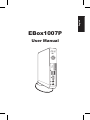
English
EBox1007P
User Manual
E7312
English
First Edition
March 2012
Copyright © 2012 ASUSTeK COMPUTER INC. All Rights Reserved.
No part of this manual, including the products and software described in it, may
be reproduced, transmitted, transcribed, stored in a retrieval system, or translated
into any language in any form or by any means, except documentation kept by the
purchaser for backup purposes, without the express written permission of ASUSTeK
COMPUTER, INC. (“ASUS”).
Products and corporate names mentioned in this manual may or may not be
registered trademarks or copyrights of their respective companies, and are used
for identification purposes only. All trademarks are the property of their respective
owners.
Every effort has been made to ensure that the contents of this manual are correct
and up to date. However, the manufacturer makes no guarantee regarding the
accuracy of its contents, and reserves the right to make changes without prior
notice.
Contents
English
Contents........................................................................................................ 3
Notices........................................................................................................... 4
Safety information..................................................................................... 9
Global Environmental Regulation Compliance and
Declaration .........................................................................................11
ASUS Recycling/Takeback Services............................................11
ENERGY STAR complied product.................................................12
Notes for this manual.............................................................................12
Welcome.....................................................................13
Package contents.....................................................................................13
Knowing your PC.......................................................14
Front view...................................................................................................14
Rear view.....................................................................................................16
Top view......................................................................................................18
Bottom view..............................................................................................19
Positioning your PC...................................................20
Installing the stand (optional).............................................................20
Installing your PC to a monitor (optional)......................................21
Setting up your PC.....................................................22
Connecting to a display.........................................................................22
Connecting to USB devices..................................................................22
Connecting to a network device........................................................23
Connecting to LAN...........................................................................23
Connecting to Wi-Fi via wireless antenna................................23
Turning on the system...........................................................................24
Using your PC.............................................................25
Configuring wireless connection.......................................................25
Configuring wired connection............................................................26
ASUS Easy Update...................................................................................30
Recovering your system............................................31
Using the recovery partition................................................................31
Using the USB storage device (USB Restore).................................33
EB1007P
3
Notices
English
Federal Communications Commission Statement
This device complies with Part 15 of the FCC Rules. Operation is
subject to the following two conditions:
• This device may not cause harmful interference, and
• This device must accept any interference received including
interference that may cause undesired operation.
This equipment has been tested and found to comply with the limits
for a Class B digital device, pursuant to Part 15 of the FCC Rules.
These limits are designed to provide reasonable protection against
harmful interference in a residential installation. This equipment
generates, uses and can radiate radio frequency energy and, if not
installed and used in accordance with manufacturer’s instructions,
may cause harmful interference to radio communications. However,
there is no guarantee that interference will not occur in a particular
installation. If this equipment does cause harmful interference to
radio or television reception, which can be determined by turning
the equipment off and on, the user is encouraged to try to correct
the interference by one or more of the following measures:
• Reorient or relocate the receiving antenna.
• Increase the separation between the equipment and receiver.
• Connect the equipment to an outlet on a circuit different from
that to which the receiver is connected.
• Consult the dealer or an experienced radio/TV technician for
help.
CAUTION: Any changes or modifications not expressly approved by
the grantee of this device could void the user’s authority to operate
the equipment.
4
EB1007P
RF exposure warning
English
This equipment must be installed and operated in accordance with
provided instructions and the antenna(s) used for this transmitter
must be installed to provide a separation distance of at least 20
cm from all persons and must not be co-located or operating in
conjunction with any other antenna or transmitter. End-users and
installers must be provide with antenna installation instructions
and transmitter operating conditions for satisfying RF exposure
compliance.
Declaration of Conformity
(R&TTE directive 1999/5/EC)
The following items were completed and are considered relevant
and sufficient:
•
•
•
•
Essential requirements as in [Article 3]
Protection requirements for health and safety as in [Article 3.1a]
Testing for electric safety according to [EN 60950]
Protection requirements for electromagnetic compatibility in
[Article 3.1b]
• Testing for electromagnetic compatibility according to [EN 301
489-1] & [EN 301 489-17]
• Effective use of the radio spectrum as in [Article 3.2]
• Radio test suites according to [EN 300 328-2]
EB1007P
5
CE Marking
English
CE marking for devices without wireless LAN/Bluetooth
The shipped version of this device complies with the requirements
of the EEC directives 2004/108/EC “Electromagnetic compatibility”
and 2006/95/EC “Low voltage directive”.
CE marking for devices with wireless LAN/ Bluetooth
This equipment complies with the requirements of Directive 1999/5/
EC of the European Parliament and Commission from 9 March, 1999
governing Radio and Telecommunications Equipment and mutual
recognition of conformity.
Wireless Operation Channel for Different Domains
6
N. America
2.412-2.462 GHz
Ch01 through CH11
Japan
2.412-2.484 GHz
Ch01 through Ch14
Europe ETSI
2.412-2.472 GHz
Ch01 through Ch13
EB1007P
France Restricted Wireless Frequency Bands
English
Some areas of France have a restricted frequency band. The worst
case maximum authorized power indoors are:
• 10mW for the entire 2.4 GHz band (2400 MHz–2483.5 MHz)
• 100mW for frequencies between 2446.5 MHz and 2483.5 MHz
Channels 10 through 13 inclusive operate in the band 2446.6 MHz
to 2483.5 MHz.
There are few possibilities for outdoor use: On private property or on
the private property of public persons, use is subject to a preliminary
authorization procedure by the Ministry of Defense, with maximum
authorized power of 100mW in the 2446.5–2483.5 MHz band. Use
outdoors on public property is not permitted.
In the departments listed below, for the entire 2.4 GHz band:
• Maximum authorized power indoors is 100mW
• Maximum authorized power outdoors is 10mW
Departments in which the use of the 2400–2483.5 MHz band is
permitted with an EIRP of less than 100mW indoors and less than
10mW outdoors:
01 Ain
02 Aisne
03 Allier
05 Hautes Alpes 08 Ardennes
09 Ariège
11 Aude
12 Aveyron
16 Charente
24 Dordogne
25 Doubs
26 Drôme
32 Gers
36 Indre
37 Indre et Loire
41 Loir et Cher
45 Loiret
50 Manche
55 Meuse
58 Nièvre
59 Nord
60 Oise
61 Orne
63 Puy du Dôme
64 Pyrénées Atlantique
66 Pyrénées Orientales
67 Bas Rhin
68 Haut Rhin
70 Haute Saône
71 Saône et Loire
75 Paris
82 Tarn et Garonne
84 Vaucluse
88 Vosges
89 Yonne
90 Territoire de Belfort
94 Val de Marne
EB1007P
7
English
This requirement is likely to change over time, allowing you to use
your wireless LAN card in more areas within France. Please check
with ART for the latest information (www.arcep.fr)
Your WLAN Card transmits less than 100mW, but more than 10mW.
Canadian Department of Communications Statement
This digital apparatus does not exceed the Class B limits for
radio noise emissions from digital apparatus set out in the
Radio Interference Regulations of the Canadian Department of
Communications.
This class B digital apparatus complies with Canadian ICES-003.
IC Radiation Exposure Statement for Canada
This equipment complies with IC radiation exposure limits set forth
for an uncontrolled environment. To maintain compliance with IC
RF exposure compliance requirements, please avoid direct contact
to the transmitting antenna during transmitting. End users must
follow the specific operating instructions for satisfying RF exposure
compliance.
Operation is subject to the following two conditions:
• This device may not cause interference and
• This device must accept any interference, including interference
that may cause undesired operation of the device.
REACH
Complying with the REACH (Registration, Evaluation, Authorization,
and Restriction of Chemicals) regulatory framework, we publish
the chemical substances in our products at ASUS REACH website at
http://csr.asus.com/english/REACH.htm.
8
EB1007P
Safety information
English
Your PC is designed and tested to meet the latest standards of safety
for information technology equipment. However, to ensure your
safety, it is important that you read the following safety instructions.
Setting up your system
• Read and follow all instructions in the documentation before you
operate your system.
• Do not use this product near water or a heated source such as a
radiator.
• Set up the system on a stable surface with the provided stand.
Never use the system alone without the stand.
• Openings on the chassis are for ventilation. Do not block or cover
these openings. Make sure you leave plenty of space around the
system for ventilation. Never insert objects of any kind into the
ventilation openings.
• Use this product in environments with ambient temperatures
between 0˚C and 35˚C.
• If you use an extension cord, make sure that the total ampere
rating of the devices plugged into the extension cord does not
exceed its ampere rating.
Care during use
• Do not walk on the power cord or allow anything to rest on it.
• Do not spill water or any other liquids on your system.
• When the system is turned off, a small amount of electrical
current still flows. Always unplug all power, modem, and network
cables from the power outlets before cleaning the system.
• If you encounter the following technical problems with the
product, unplug the power cord and contact a qualified service
technician or your retailer.
•
The power cord or plug is damaged.
•
Liquid has been spilled into the system.
EB1007P
9
English
•
•
•
The system does not function properly even if you follow
the operating instructions.
The system was dropped or the cabinet is damaged.
The system performance changes.
Lithium-Ion Battery Warning
CAUTION: Danger of explosion if battery is incorrectly
replaced. Replace only with the same or equivalent type
recommended by the manufacturer. Dispose of used batteries
according to the manufacturer’s instructions.
LASER PRODUCT WARNING
CLASS 1 LASER PRODUCT
NO DISASSEMBLY
The warranty does not apply to the products that
have been disassembled by users
DO NOT throw the PC in municipal waste. This product has been
designed to enable proper reuse of parts and recycling. This
symbol of the crossed out wheeled bin indicates that the product
(electrical, electronic equipment, and mercury-containing button
cell battery) should not be placed in municipal waste. Check local
technical support services for product recycling.
DO NOT throw the battery in municipal waste. This symbol of the
crossed out wheeled bin indicates that the battery should not be
placed in municipal waste. Check local technical support services
for battery replacement.
10
EB1007P
English
Global Environmental Regulation Compliance and
Declaration
ASUS follows the green design concept to design and manufacture
our products, and makes sure that each stage of the product
life cycle of ASUS product is in line with global environmental
regulations. In addition, ASUS disclose the relevant information
based on regulation requirements.
Please refer to http://csr.asus.com/english/Compliance.htm for
information disclosure based on regulation requirements ASUS is
complied with:
Japan JIS-C-0950 Material Declarations
EU REACH SVHC
Swiss Energy Laws
ASUS Recycling/Takeback Services
ASUS recycling and takeback programs come from our commitment
to the highest standards for protecting our environment. We believe
in providing solutions for you to be able to responsibly recycle our
products, batteries, other components as well as the packaging
materials. Please go to http://csr.asus.com/english/Takeback.htm for
detailed recycling information in different regions.
EB1007P
11
ENERGY STAR complied product
English
ENERGY STAR is a joint program of the U.S.
Environmental Protection Agency and the U.S.
Department of Energy helping us all save money
and protect the environment through energy
efficient products and practices.
All ASUS products with the ENERGY STAR
logo comply with the ENERGY STAR standard, and the power
management feature is enabled by default. The monitor and
computer are automatically set to sleep after 15 and 30 minutes of
user inactivity. To wake your computer, click the mouse or press any
key on the keyboard.
Please visit http://www.energy.gov/powermanagement for
detail information on power management and its benefits to the
environment. In addition, please visit http://www.energystar.gov for
detail information on the ENERGY STAR joint program.
ENERGY STAR is NOT supported on FreeDOS-based products or
without OS.
Notes for this manual
To make sure that you perform certain tasks properly, take note of
the following symbols used throughout this manual.
WARNING: Vital information that you MUST follow to prevent
injury to yourself.
IMPORTANT: Instructions that you MUST follow to complete a
task.
TIP: Tips and useful information that help you complete a task.
NOTE: Additional information for special situations.
12
EB1007P
Welcome
English
Congratulations on your purchase of the PC. The following
illustration displays the package contents of your new PC. If any of
the below items is damaged or missing, contact your retailer.
Package contents
PC
Stand and screw (optional)
VESA mount and Screw pack
(optional)
Antenna
AC adapter
Power cord
Quick
Warranty card
Start G
uide
Quick start guide
If the device or its components fail or malfunction during normal
and proper use within the warranty period, bring the warranty
card to the ASUS Service Center for replacement of the defective
components.
EB1007P
13
Knowing your PC
English
Front view
Refer to the diagram below to identify the components on this side
of the system.
1
2
3
4
5
6
14
1
Hard disk LED
The hard disk LED blinks when data is being written into or
read from the hard disk drive.
2
Power switch
The power switch allows powering ON and OFF the system.
EB1007P
Memory card slot
The built-in memory card reader reads MMC/SD/SDHC
cards used in devices like digital cameras, MP3 players,
mobile phones, and PDAs.
4
USB port
The USB (Universal Serial Bus) port is compatible with
USB devices such as keyboards, mouse devices, cameras,
and hard disk drives. USB allows many devices to run
simultaneously on a single computer, with some peripheral
acting as additional plug-in sites or hubs.
5
Headphone/Audio Out jack
The stereo headphone jack (3.5mm) is used to connect
the system’s audio out signal to amplified speakers or
headphones.
6
Microphone jack
The microphone jack is designed to connect the
microphone used for video conferencing, voice narrations,
or simple audio recordings.
EB1007P
English
3
15
Rear view
English
Refer to the diagram below to identify the components on this side
of the system.
1
2
3
4
5
6
1
Antenna jack
The jack is used to connect the supplied wireless antenna to
enhance wireless signal reception.
The antenna is installable/ removable according to need.
Fasten the antenna onto the PC for better signal reception
when Wi-Fi is in use.
16
EB1007P
Power input (DC 19V)
The supplied power adapter converts AC power to DC
power for use with this jack. Power supplied through this
jack supplies power to the PC. To prevent damage to the PC,
always use the supplied power adapter.
English
2
The power adapter may become warm to hot when in use. Do
not cover the adapter and keep it away from your body.
3
USB port
The USB (Universal Serial Bus) port is compatible with
USB devices such as keyboards, mouse devices, cameras,
and hard disk drives. USB allows many devices to run
simultaneously on a single computer, with some peripheral
acting as additional plug-in sites or hubs.
4
LAN port
The eight-pin RJ-45 LAN port supports a standard Ethernet
cable for connection to a local network.
5
Display (Monitor) Output
The 15-pin D-sub monitor port supports a standard
VGA-compatible device such as a monitor or projector to
allow viewing on a larger external display.
6
Headphone/Audio Out jack
The stereo headphone jack (3.5mm) is used to connect
the system’s audio out signal to amplified speakers or
headphones.
EB1007P
17
Top view
English
Refer to the diagram below to identify the components on this side
of the system.
E-SATA
1
1
E-SATA e-SATA
2
18
2
Port
External SATA or eSATA allows external connection of
Serial-ATA devices originally designed for use inside the
computer. It is up to six times faster than existing USB 2.0, &
1394 for external storage solutions and is also hot pluggable
using shielded cables and connectors up to two meters.
USB port
The USB (Universal Serial Bus) port is compatible with
USB devices such as keyboards, mouse devices, cameras,
and hard disk drives. USB allows many devices to run
simultaneously on a single computer, with some peripheral
acting as additional plug-in sites or hubs.
EB1007P
Bottom view
English
Refer to the diagram below to identify the components on this side
of the system.
1
1
Kensington® Lock Port
The Kensington® lock port allows the PC to be secured
using Kensington® compatible security products. These
security products usually include a metal cable and lock
that prevent the PC to be removed from a fixed object.
EB1007P
19
Positioning your PC
English
Installing the stand (optional)
Erect your PC with the optional stand. To do so:
1. Locate the screw hole on the bottom of the PC.
2. Align the stand screw to the PC screw hole, and then secure the
stand to the PC with a coin.
PC bottom view
1
Screw hole
Stand screw
2
20
EB1007P
English
Installing your PC to a monitor
(optional)
You can also install your PC to the back of a monitor. To do so:
1. Secure the optional VESA mount to your monitor with four
screws (HNM/M4 x 8).
To fasten the VESA mount, your monitor must comply with VESA75
or VESA100 standard.
2. Place your PC on the VESA mount noting the correct alignment,
and then secure the PC to the VESA mount with a coin.
PC bottom view
EB1007P
21
Setting up your PC
You need to connect peripherals before using your PC.
English
Connecting to a display
Connect one end of the VGA cable to an LCD monitor ( 1 ) and the
other end to the Display (Monitor) Output port on the system rear
panel ( 2 ).
2
LCD monitor
1
Connecting to USB devices
Connect USB devices like wired/wireless keyboards (varying with
areas), mouse devices, and printers to the USB ports on the system
rear panel.
22
EB1007P
English
Connecting to a network device
Connecting to LAN
Connect one end of a network cable to the LAN port on the system
rear panel and the other end to a hub or switch.
Network cable with RJ-45 connectors
Network hub or switch
Connecting to Wi-Fi via wireless antenna
The wireless antenna is provided for enhancing wireless signal
reception. The antenna is installable/ removable according to need. Fasten
the antenna onto the PC for better signal reception when Wi-Fi is in use.
EB1007P
23
Turning on the system
English
Connect the supplied AC adapter to the DC IN jack on the system
rear panel, and then press the power switch on the front panel to
turn on the system.
3
4
2
1
• When your PC is not in use, unplug the power adapter or switch
off the AC outlet to save on power consumption.
• Adjust the power management settings in the Window®
Control Panel. This is to ensure that your PC is set to a low
power consumption mode and is fully operational at the same
time.
To enter the BIOS setup, press <F2> repeatedly during bootup.
24
EB1007P
Using your PC
English
All screenshots in this section are for reference only. Actual screen
images may vary with operating systems. Visit the ASUS website at
www.asus.com for the latest information.
This PC is not supported under Windows® 8.
Configuring wireless connection
To connect to a wireless network, follow the instructions below:
For security concerns, DO NOT connect to an unsecured network.
Otherwise, the transmitted information without encryption might
be visible to others.
1. Click the wireless network icon with an orange star
Windows® Notification area.
in the
2. Select the wireless access point you
want to connect to from the list and click
Connect to build the connection.
If you cannot find the desired access
point, click the Refresh icon on the
upper right corner to refresh and search
in the list again.
3. When connecting, you may have to enter a password.
4. After a connection has been established, the connection is
shown on the list.
5. You can see the wireless network icon
in the Notification
area.
EB1007P
25
Configuring wired connection
English
To establish a wired network, follow the instructions below:
Using a dynamic IP / PPPoE network connection:
1. Click the network icon with a
yellow warning triangle
in the
Windows® Notification area and
select Open Network and Sharing
Center.
2. Click Change adapter
settings in the left blue
pane.
3. Right-click Local Area
Connection and select
Properties.
26
EB1007P
5. Click Obtain an IP address
automatically and click
OK.
English
4. Click Internet Protocol
Version 4(TCP/IPv4) and
click Properties.
(Continue the following steps if using PPPoE)
6. Return to the Network
and Sharing Center and
then click Set up a new
connection or network.
EB1007P
27
English
28
7. Select Connect to the
Internet and click Next.
8. Select Broadband (PPPoE)
and click Next.
9. Enter your User name and,
Password, and Connection
name. Click Connect.
10. Click Close to finish the
configuration.
11. Click the network icon
in the taskbar and click
the connection you just
created.
12. Enter your user name and
password. Click Connect to
connect to the Internet.
EB1007P
English
Using a static IP:
1. Repeat steps 1–4 in Using a
dynamic IP to start the static IP
network configuration.
2 Click Use the following IP
address.
3. Enter the IP address, Subnet
mask and Gateway from your
service provider.
4. If needed, enter the preferred
DNS Server address and
alternative address.
5. After entering all the related values, click OK to build the
network connection.
EB1007P
29
ASUS Easy Update
English
ASUS Easy Update is a software tool that automatically detects and
downloads the latest BIOS, drivers, and applications for your PC.
1. From the Windows® notification
area, right-click the ASUS Easy
Update icon.
2. Select Schedule to set how
often you want to update
your system.
3. Select Update to activate
the update.
4. Click OK to display the
items you can download.
5. Check the item(s) you want
to download, and then click
OK.
30
EB1007P
Recovering your system
English
Using the recovery partition
The Recovery Partition includes an image of the operating system,
drivers, and utilities installed on your system at the factory. The
recovery partition provides a comprehensive recovery solution that
quickly restores your system’s software to its original working state,
provided that your hard disk drive is in good working order. Before
using the recovery partition, copy your data files (such as Outlook
PST files) to a USB device or to a network drive and make note of any
customized configuration settings (such as network settings).
Recovering the Windows OS to the Factory Default
Partition (F9 Recovery)
1. Press [F9] during bootup.
2. Select Windows setup [EMS Enabled] when this item appears
and press [Enter].
3. Select the language and click Next.
4. Select Recover the OS to the Default Partition and click Next.
5. The factory default partition will be displayed. Click Next.
6. Data on the default partition will be cleared. Click Recover to
start the system recovery.
You will lose all your data on the selected partition. Ensure to back
up your important data beforehand.
7. When recovery is successfully completed, click Reboot to restart
the system.
EB1007P
31
English
Backing up the Factory Default Environment Data to a
USB Drive (F9 Backup)
1. Repeat steps 1–3 in the previous section.
2. Select Backup the Factory Environment to a USB Drive and
click Next.
3. Connect a USB storage device to your PC to start the Factory
Default Environment backup.
The required size of the connected USB storage device should be
larger than 20GB. The actual size may vary with your PC model.
4. Select a desired USB storage device if more than one USB
storage device is connected to your PC and click Next.
If there is already a partition with proper size in the selected USB
storage device (for example, a partition that has been used as the
backup partition), the system will show this partiton automatically
and reuse it for backup.
5. Based on the different situations in the previous step, data on
the selected USB storage device or on the selected partition will
be cleared. Click Backup to start backup.
You will lose all your data on the selected USB storage device or
on the selected partition. Ensure to back up your important data
beforehand.
6. When backing up the factory default environment is
successfully completed, click Reboot to restart the system.
32
EB1007P
English
Using the USB storage device (USB
Restore)
When the Recovery Partition in your system is crashed, use the USB
storage device to restore the system to the factory default partition
or the factory environment data to the entire hard disk.
1. Connect the USB storage device that you back up the factory
environment data to.
2. Press <F8> for on bootup and the Please select boot device
screen appears. Select USB:XXXXXX to boot from the connected
USB storage device.
3. Select the language and click Next.
4. Select Restore and click Next.
5. Select a task and click Next. Task options:
Restore the OS to the Default Partition only
Select this option if you simply want to restore the OS to the
factory default partition. This option deletes all data on the
system partition “C” and keeps the partition “D” unchanged.
After you click Next, the factory default partition will be
displayed. Click Next again.
Restore the Whole Hard Disk
Select this option if you want to restore your PC to the factory
default state. This option deletes all data from your hard disk
and creates a new system partition as drive “C” , an empty
partition as drive “D“ and a Recovery Partition.
6. Data on the factory default partition or on the whole hard disk
will be cleared depending on the option you selected in the
previous step. Click Restore to start the task.
7. When restore is successfully completed, click Reboot to restart
the system.
EB1007P
33
ASUS contact information
English
ASUSTeK COMPUTER INC.
Address
Telephone Fax E-mail
Web site
15 Li-Te Road, Peitou, Taipei, Taiwan 11259
+886-2-2894-3447
+886-2-2890-7798
[email protected]
www.asus.com.tw
Technical Support
Telephone Online support
+86-21-38429911
support.asus.com
ASUS COMPUTER INTERNATIONAL (America)
Address
Telephone
Fax
Web site
800 Corporate Way, Fremont, CA 94539, USA
+1-510-739-3777
+1-510-608-4555
usa.asus.com
Technical Support
Telephone Support fax
Online support
+1-812-282-2787
+1-812-284-0883
support.asus.com
ASUS COMPUTER GmbH (Germany and Austria)
Address
Fax
Web site
Online contact
Harkort Str. 21-23, D-40880 Ratingen, Germany
+49-2102-959911
www.asus.de
www.asus.de/sales
Technical Support
Component Telephone
System/Notebook/Eee/
LCD Telephone
Support Fax
Online support
34
EB1007P
+49-1805-010923
+49-1805-010920
+49-2102-9599-11
support.asus.com