1
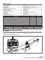
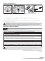
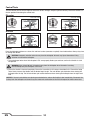
Instruction Manual
Bedienungsanleitung
Manuel d’utilisation
Manuale di Istruzioni
RTF
READY-TO-FLY
NOTICE
All instructions, warranties and other collateral documents are subject to change at the sole discretion of Horizon
Hobby, LLC. For up-to-date product literature, visit horizonhobby.com and click on the support tab for this product.
Meaning of Special Language
The following terms are used throughout the product literature to indicate various levels of potential harm when
operating this product:
NOTICE: Procedures, which if not properly followed, create a possibility of physical property damage AND a little or no
possibility of injury.
CAUTION: Procedures, which if not properly followed, create the probability of physical property damage AND a
possibility of serious injury.
WARNING: Procedures, which if not properly followed, create the probability of property damage, collateral damage,
and serious injury OR create a high probability of superficial injury.
WARNING: Read the ENTIRE instruction manual to become familiar with the features of the product before
operating. Failure to operate the product correctly can result in damage to the product, personal property and
cause serious injury.
This is a sophisticated hobby product. It must be operated with caution and common sense and requires some basic
mechanical ability. Failure to operate this Product in a safe and responsible manner could result in injury or damage
to the product or other property. This product is not intended for use by children without direct adult supervision. Do
not use with incompatible components or alter this product in any way outside of the instructions provided by Horizon
Hobby, LLC. This manual contains instructions for safety, operation and maintenance. It is essential to read and follow
all the instructions and warnings in the manual, prior to assembly, setup or use, in order to operate correctly and avoid
damage or serious injury.
Age Recommendation: Not for children under 14 years. This is not a toy.
Safety Precautions and Warnings
• Always keep a safe distance in all directions around
your model to avoid collisions or injury. This model is
controlled by a radio signal subject to interference from
many sources outside your control. Interference can
cause momentary loss of control.
• Always operate your model in open spaces away from
full-size vehicles, traffic and people.
• Always carefully follow the directions and warnings for
this and any optional support equipment
(chargers, rechargeable battery packs, etc.).
• Always keep all chemicals, small parts and anything
electrical out of the reach of children.
• Always avoid water exposure to all equipment not
specifically designed and protected for this purpose.
Moisture causes damage to electronics.
• Never place any portion of the model in your mouth as it
could cause serious injury or even death.
• Never operate your model with low transmitter
batteries.
• Always keep aircraft in sight and under control.
• Always move the throttle fully down at rotor strike.
• Always use fully charged batteries.
• Always keep transmitter powered on while aircraft is
powered.
• Always remove batteries before disassembly.
• Always keep moving parts clean.
• Always keep parts dry.
• Always let parts cool after use before touching.
• Always remove batteries after use.
• Never operate aircraft with damaged wiring.
• Never touch moving parts.
WARNING AGAINST COUNTERFEIT PRODUCTS: If you ever need to replace your Spektrum receiver found in
a Horizon Hobby product, always purchase from Horizon Hobby, LLC or a Horizon Hobby authorized dealer to
ensure authentic high-quality Spektrum product. Horizon Hobby, LLC disclaims all support and warranty with regards,
but not limited to, compatibility and performance of counterfeit products or products claiming compatibility with
DSM or Spektrum.
EN
2
Table of Contents
First Flight Preparation .....................................................4
Flying Checklist ...............................................................4
Charging Warnings...........................................................4
Battery Charging..............................................................5
Installing the Transmitter Batteries (RTF) ..........................5
Transmitter Setup Table ...................................................6
Installing the Flight Battery ..............................................7
Transmitter and Receiver Binding.....................................7
SAFE Technology .............................................................8
Panic Recovery ................................................................8
Transmitter Control ..........................................................9
Flight Mode and Rate Selection ........................................9
Control Tests ..................................................................10
Understanding the Primary Flight Controls .....................11
Flying the 200 SR X .......................................................12
Post-Flight Inspection and Maintenance Checklist ..........12
Troubleshooting Guide ...................................................13
Exploded View ...............................................................14
Parts Listings .................................................................14
Limited Warranty ...........................................................15
Warranty and Service Contact Information .....................16
FCC Information .............................................................16
IC Information ...............................................................16
Compliance Information for the European Union .............17
Features
Airframe – Blade ® 200 SR X
Main Motor - 3900Kv Brushless
Tail Motor - 5100Kv Brushless
Recevier - Spektrum™ AR636H Receiver
ESC - Dual Brushless ESC
Battery – 800mAh 3S 11.1V 30C Li-Po
Charger – 3S 0.8A Li-Po Balancing Charger with AC to DC Adapter
Transmitter – LP6DSM SAFE™ Transmitter
Length
Height
Main Rotor Diameter
RTF
Included
Installed
Installed
Installed
Installed
Included
Included
Included
BNF
Included
Installed
Installed
Installed
Installed
Included
Included
Required
Specifications
14.76 in (375mm)
3.25 in (82.5mm)
Tail Rotor Diameter
5.31 in (135mm)
8.82 oz (250 g)
Flying Weight
16.14 in (410mm)
To register your product online,visit www.bladehelis.com
Box Contents
• Blade 200 SR X
• 800mAh 3S 11.1V 30C Li-Po Battery
• 3S Li-Po Balancing Charger with AC to DC Adapter
• LP6DSM SAFE Transmitter (RTF Only)
• 4 AA Batteries (RTF Only)
3
EN
First Flight Preparation
Flying Checklist
• Remove and inspect contents
• Begin charging the flight battery
• Install the flight battery in the helicopter
(once it has been fully charged)
• Program your computer transmitter (BNF only)
• Bind your transmitter (BNF only)
• Familiarize yourself with the controls
• Find a suitable area for flying
❏ Always turn the transmitter on first
❏ Plug the flight battery into the lead from the ESC
❏ Allow the receiver and ESC to initialize and arm properly
❏ Fly the model
❏ Land the model
❏ Unplug the flight battery from the ESC
❏ Always turn the transmitter off last
Charging Warnings
The battery charger (EFLC3105) included with your
helicopter has been designed to safely charge the Li-Po
battery.
• Always charge batteries away from flammable materials.
• Always inspect the battery before charging.
• Always disconnect the battery after charging, and let the
charger cool between charges.
• Always constantly monitor the temperature of the battery
pack while charging.
• ONLY USE A CHARGER SPECIFICALLY DESIGNED TO CHARGE
LI-PO BATTERIES. Failure to charge the battery with a
compatible charger may cause a fire resulting in personal
injury and/or property damage.
• Never discharge Li-Po cells to below 3V under load.
• Never cover warning labels with hook and loop strips.
• Never leave charging batteries unattended.
• Never charge batteries outside recommended levels.
• Never charge damaged batteries.
• Never attempt to dismantle or alter the charger.
• Never allow minors to charge battery packs.
• Never charge batteries in extremely hot or cold places
(recommended between 40–120° F or 5–49° C) or place in
direct sunlight.
CAUTION: All instructions and warnings must be
followed exactly. Mishandling of Li-Po batteries
can result in a fire, personal injury and/or property
damage.
• By handling, charging or using the included Li-Po battery,
you assume all risks associated with lithium batteries.
• If at any time the battery begins to balloon or swell,
discontinue use immediately. If charging or discharging,
discontinue and disconnect. Continuing to use, charge or
discharge a battery that is ballooning or swelling can result
in fire.
• Always store the battery at room temperature in a dry area
for best results.
• Always transport or temporarily store the battery in a
temperature range of 40–120º F (5–49° C). Do not store the
battery or model in a car or direct sunlight. If stored in a hot
car, the battery can be damaged or even catch fire.
EN
4
Battery Charging
NOTICE: Charge only batteries that are cool to the touch and
are not damaged. Look at the battery to make sure it is not
damaged e.g., swollen, bent, broken or punctured.
1. Connect the AC to DC adapter to an AC outlet.
2. Connect the AC to DC adapter to the charger.
3. Connect the battery balance lead to the charger.
The connector is keyed to prevent reverse
polarity connection.
4. Always disconnect the flight battery from the charger
immediately upon completion of charging.
LED Indicators
Red Flashing LED: Input power with no battery connected
Red and Green Solid LEDs: Battery connected and
charging
Red Solid LED: Charge complete
Red and Green Flashing LEDs: Charge error
Charging a fully discharged (not over-discharged) 800mAh battery takes approximately 1–1.5 hours.
The charger can also be powered through the DC alligator clips. Connect them to a 11.5–15V DC power source, noting
proper polarity.
CAUTION: Do not connect to AC and DC power sources at the same time. Doing so may cause a short circuit,
resulting in damage to the product, personal injury or property damage.
NOTICE: Always connect cable polarities correctly. Consult the battery instructions, safety sheet or product support before
using a 12V battery with sources other than a standard AC wall outlet.
Installing the Transmitter Batteries (RTF)
Replace the transmitter batteries
when the transmitter beeps.
5
EN
EN
6
Acro
DX9/DX18
DX5e (New)
w/ 3 Position
Switch
Acro
N/A
DX4e (New)
w/ 3 Position
Switch
DX8
N/A
MLP6DSM
Acro
N/A
Transmitter
DX7/7SE
Model
Type
AUX1 = REV
Throttle Travel =
85% Low, 100% Full
AUX1 = REV
All Others = NORM
Throttle Travel =
85% Low, 100% Full
AUX1=REV
Throttle Travel =
85% Low, 100% Full
Flap=INH
Trainer=AUX1
Gear=INH
F Mode=Gear
Channel Input
Config
5 GEAR = B
6 AUX 1 = I
All channels = NORM
All channels = NORM
N/A
Reversing Setup
Gear=INH
Flap=GEAR
Trainer=Aux1
MIX=NOR
MIX=NOR
DIP Switches:
1, 2, 4, 5, 6, 7,
9, and 10 = OFF
3 and 8 = ON
Setup /
Channel
Assignments
Switch B Pos 2 = Experienced
Switch B Pos 1 = Intermediate
Switch B Pos 0 = Beginner
Switch B Pos 2 = Experienced
Switch B Pos 1 = Intermediate
Switch B Pos 0 = Beginner
Gyro Switch Pos 2 = Experienced
Gyro Switch Pos 1 = Intermediate
Gyro Switch Pos 0 = Beginner
CH 5 Pos 2 = Experienced
CH 5 Pos 1 = Intermediate
CH 5 Pos 0 = Beginner
CH 5 Pos 2 = Experienced
CH 5 Pos 1 = Intermediate
CH 5 Pos 0 = Beginner
CH 5 Pos 2 = Experienced
CH 5 Pos 1 = Intermediate
CH 5 Pos 0 = Beginner
Flight Modes
Ail D/R switch = Ail D/R
Ele D/R switch = Ail D/R
Rud D/R switch = Ail D/R
Ail D/R switch = Ail D/R
Ele D/R switch = Ail D/R
Rud D/R switch = Ail D/R
Ail D/R switch = Ail D/R
Ele D/R switch = Ail D/R
Rud D/R switch = Ail D/R
Ail/Ele/Rud
Ail/Ele/Rud
Default
Dual Rates
100%
100%
100%
100%
Fixed
100%
Fixed
100%
Fixed
Hgh
Rate
70%
70%
70%
70%
Fixed
70%
Fixed
70%
Fixed
Low
Rate
Timer
Count Down
08:00 Tone
Start: Throttle Out
Timer
Count Down
08:00 Tone
Start: Throttle Out
Pos: 25%
Timer
Count Down
08:00 Tone
Start: Throttle Out
Pos: 25%
Other Settings
Transmitter Setup Table
Installing the Flight Battery
1
2
3
1. Lower the throttle stick to the lowest position. If your transmitter utilizes mechanical trims (like the included RTF
transmitter), set the throttle trim to the highest position. Set all other trims to the center position.
2. Power ON the transmitter.
3. Attach the hook material to the helicopter frame and the loop material to the flight battery.
4. Install the flight battery on the helicopter frame. Secure the flight battery with the hook and loop strap.
5. Connect the battery connector to the ESC.
6. Place the helicopter on a flat surface and leave it still until the ESC beeps twice and the blue LED glows solid,
indicating initialization is complete.
If you experience issues during initialization, refer to the Troubleshooting Guide at the back of the manual.
CAUTION: Always disconnect the Li-Po battery from the aircraft when not flying to avoid over-discharging the
battery. Batteries discharged to a voltage lower than the lowest approved voltage may become damaged,
resulting in loss of performance and potential fire when batteries are charged.
Transmitter and Receiver Binding
To bind or re-bind your helicopter to your chosen transmitter, please follow the directions below.
General Binding Procedure
1. Disconnect the flight battery from the helicopter.
2. Refer the Transmitter Setup Table to correctly setup your transmitter.
3. Lower the throttle stick to the lowest position. If your transmitter utilizes mechanical trims (like the included RTF
transmitter), set the throttle trim to the highest position. Set all other trims to the center position.
4. Power off the transmitter and move all switches to the 0 position. Move the throttle to the low/off position.
5. Install the bind plug in the receiver BIND/PROG port.
6. Connect the flight battery to the ESC. The receiver LED flashes, indicating it is in bind mode.
7. Put the transmitter into bind mode while powering on the transmitter.
8. Release the bind button/switch after 2–3 seconds. The helicopter is bound when the LED on the receiver turns solid.
9. Disconnect the flight battery and power the transmitter off.
CAUTION: When using a Futaba® transmitter with a Spektrum™ DSM2 ®/DSMX ® module, you must reverse the
throttle channel and re-bind. Refer to your Spektrum module manual for binding and failsafe instructions.
Refer to your Futaba transmitter manual for instructions on reversing the throttle channel.
7
EN
RTF
Your RTF transmitter comes prebound to the model. If you need to re-bind, follow the directions below.
LP6DSM Binding Procedure
1. Disconnect the flight battery from the helicopter.
2. Lower the throttle stick to the lowest position. Set the throttle trim to the highest position.
Set all other trims to the center position.
3. Power off the transmitter.
4. Install the bind plug in the receiver BIND/PROG port.
5. Connect the flight battery to the ESC. The receiver LED flashes, indicating it is in bind mode.
6. When the LED is flashing, press and hold the Bind Switch while powering on the transmitter.
7. The transmitter will beep and the LED will blink. Release the Bind Switch when the transmitter stops beeping.
8. The helicopter is bound when the LED on the receiver control unit is solid.
9. Disconnect the flight battery and power the transmitter off.
If you encounter problems, obey binding instructions and refer to the troubleshooting guide for other instructions.
If needed, contact the appropriate Horizon Product Support office. For a list of compatible DSM® transmitters, please
visit www.bindnfly.com.
™
Technology
Revolutionary SAFE™ (Sensor Assisted Flight Envelope) technology uses an innovative combination of multi-axis sensors
and software that allows model aircraft to know its position relative to the horizon. This spatial awareness is utilized to create
a controlled flight envelope the aircraft can use to maintain a safe region of bank and pitch angles so you can fly more safely.
Far beyond stability, this level of protection offers multiple modes so the pilot can choose to develop his or her skills with a
greater degree of security and flight control that always feels crisp and responsive.
SAFE technology delivers:
• Flight envelope protection you can enable at the flip of a switch.
• Multiple modes let you adapt SAFE technology to your skill level instantly.
Best of all, sophisticated SAFE technology doesn’t require any work to enjoy. Every aircraft with SAFE installed is ready to use
and optimized to offer the best possible flight experience.
FlySAFERC.com
Panic Recovery
• Immediate recovery to a safe flying attitude.
• Move the throttle to 50% and return all other transmitter controls to neutral for the quickest recovery.
• This mode is intended to provide the pilot with the confidence to continue to improve their flight skills.
If you get into distress while flying in any mode, pull and hold the Bind/Panic Switch and move the control sticks to their
neutral position. The SAFE technology will return the aircraft to a stable attitude, if the aircraft is at a sufficient height with no
obstacles in its path. Release the Panic Switch to turn off Panic Recovery and return to the current flight mode.
EN
8
Transmitter Control
RTF
Bind/Panic
Switch
Volts Display
Flight Mode Switch
0 = Beginner Mode
1 = Intermediate Mode
2 = Experienced Mode
Dual Rate Switch
Back = High Rate
Forward = Low Rate
H
G
B
C
F
D
ON
A
E
H
Mode 1
A
Power LED
Mode 2
Power LED
B
C
1 2 3 4 5 6 7 8 9 10
D
E
F
G
H
Aileron (Left/Right)
Throttle (Up/Down)
Throttle
Trim
Aileron
Trim
ON/OFF
Switch
Rudder
Trim
Elevator
Trim
Rudder (Left/Right)
Elevator (Up/Down)
Aileron (Left/Right)
Elevator (Up/Down)
Elevator
Trim
Aileron
Trim
ON/OFF
Switch
Rudder
Trim
Throttle
Trim
Rudder (Left/Right)
Throttle (Up/Down)
Flight Mode and Rate Selection
Refer to the Transmitter Setup Table for which switch on your transmitter selects flight modes and specific setup information.
RTF
Change flight modes by moving the three-position flight
mode switch. Ensure the flight mode switch is in the desired
position before flying.
• In Beginner Mode (switch position 0), the bank angle is
limited to 15 degrees. When the cyclic stick is released,
the model will return to level.
• In Intermediate Mode (switch position 1), the bank angle
is limited to 35 degrees. When the cyclic stick is released,
the model will return to level.
• In Experienced Mode (switch position 2), the bank angle
is not limited. When the sticks are released, the model will
not return to level. If you lose orientation, use the Panic
Switch to return the model to a familiar orientation.
Change rates by moving the two-position dual rate switch.
• Low rate reduces the control rates, providing an easier to
fly model. Beginners should use low rate for initial flights.
• High rate provides full control and should be used by
intermediate and experience pilots.
Flight mode
switch
9
Dual rate
switch
EN
Control Tests
Test the controls prior to the first flight to ensure the servos, linkages and parts operate correctly. Ensure the throttle is in
the low position when doing the control tests.
Elevator
Left Side View
Left Side View
Elevator up
Elevator down
Aileron
Rear View
Rear View
Aileron right
Aileron left
Motor
Place the helicopter outdoors on a clean, flat and level surface (concrete or asphalt) free of obstructions. Always stay clear
of moving rotor blades.
CAUTION: Keep pets and other animals away from the helicopter. Animals may injure themselves if they
attack or run toward the helicopter.
1. The motor beeps twice when the helicopter’s ESC arms properly. Before you continue, confirm that throttle is at full
low position.
WARNING: Stay at least 30 feet (10 meters) away from the helicopter when the motor is running.
Do not attempt to fly the helicopter at this time.
2. Ensure the throttle is lowered completely. Ensure the transmitter is still setup as described in the Transmitter Setup
Table. Slowly increase the throttle until the blades begin to spin. The main blades spin clockwise when viewing the
helicopter from the top. The tail rotor blades spin counterclockwise when viewing the helicopter from the right-hand
side.
NOTICE: If the main rotor blades are spinning counterclockwise, reduce the throttle to low immediately. Disconnect the
battery from the helicopter and reverse any two motor wire connections to the ESC and repeat the motor control test.
EN
10
Understanding the Primary Flight Controls
If you are not familiar with the controls of your 200 SR X, take a few minutes to familiarize yourself with them before
attempting your first flight.
Throttle
Left Side View
Left Side View
Descend
Climb
Throttle up
Throttle down
Rudder
Rudder right
Rudder left
Nose Yaws Right
Nose Yaws Left
Elevator
Left Side View
Elevator down
Left Side View
Elevator up
Forward
Backward
Aileron
Rear View
Aileron left
Rear View
Left
Aileron right
Right
Flying the 200 SR X
Consult your local laws and ordinances before choosing a location to fly your aircraft.
We recommend flying your aircraft outside in calm winds (3 MPH or less) or inside a large gymnasium. Always avoid
flying near houses, trees, wires and buildings. You should also be careful to avoid flying in areas where there are many
people, such as busy parks, schoolyards or soccer fields.
It is best to fly from a smooth flat surface as this will allow the model to slide without tipping over. Keep the helicopter
approximately 2 ft (600mm) above the ground. Keep the tail pointed toward you during initial flights to keep the control
orientation consistent. Releasing the stick in Beginner or Intermediate Modes will allow the helicopter to level itself and
activating the Panic Switch will level the helicopter quickly. If you become disoriented, slowly lower the throttle stick to
land softly. During initial flights, only attempt hovering the model in one spot and takeoff and landing.
11
EN
Flying the 200 SR X continued
Takeoff
Place the model onto a flat, level surface free of obstacles and walk back 30 feet (10 meters). Slowly increase the
throttle until the model is approximately 2 ft. (600mm) off the ground and check the trim so the model flies as desired.
Once the trim is adjusted, begin flying the model.
Typical flight time for the included battery is approximately 10 minutes.
Hovering
Making small corrections on the transmitter, try to hold the helicopter in one spot. If flying in calm winds, the model
should require almost no corrective inputs. After moving the cyclic stick and returning it to center the model should level
itself. The model may continue to move due to inertia. Move the cycle stick in the opposite direction to stop the movement.
After you become comfortable hovering, you can progress into flying the model to different locations, keeping the tail
pointed towards you at all times. You can also ascend and descend using the throttle stick. Once you're comfortable with
these maneuvers, you can attempt flying with the tail in different orientations. It is important to keep in mind that the
flight control inputs will rotate with the helicopter, so always try to picture the control inputs relative to the nose of the
helicopter. For example, forward will always drop the nose of the helicopter.
Low Voltage Cutoff (LVC)
LVC decreases the power to the motors when the battery voltage gets low. When the motor power decreases and the red
LED on the ESC flashes, land the aircraft immediately and recharge the flight battery.
LVC does not prevent the battery from over-discharge during storage.
NOTICE: Repeated flying to LVC will damage the battery.
Landing
To land, slowly decrease the throttle while in a low-level hover. After landing, disconnect and remove the battery from
the aircraft after use to prevent trickle discharge. Fully charge your battery before storing it. During storage, make sure
the battery charge does not fall below 3V per cell.
Post-Flight Inspection and Maintenance Checklist
√
Make sure the plastic ball link holds the control ball, but is not tight (binding) on the ball. When a link is too
loose on the ball, it can separate from the ball during flight and cause a crash. Replace worn ball links before
they fail.
Make sure the battery is not connected before cleaning. Remove dust and debris with a soft brush or a dry,
Cleaning
lint-free cloth.
Bearings
Replace bearings when they become notchy (sticky in places when turning) or draggy.
Wiring
Make sure the wiring does not contact moving parts. Replace damaged wiring and loose connectors.
Make sure there are no loose screws, other fasteners or connectors. Do not over-tighten metal screws in
Fasteners
plastic parts. Tighten screws so the parts are mated together, then turn the screw only 1/8th of a turn more.
Make sure there is no damage to rotor blades and other parts which move at high speed. Damage to these
parts includes cracks, burrs, chips or scratches. Replace damaged parts before flying. Verify both main rotor
Rotors
blades have the correct and equal tension in the blade grips. When the helicopter is held up sideways, the
main blades should support their own weight. When the helicopter is shaken lightly, the blades should fall.
Inspect the tail rotor for damage and replace if necessary. Verify the boom support bolts are tight and the
Tail
plastic ends adhere to the carbon support rods. Verify the tail motor bolts, tail rotor adapter bolts and tail motor
mount bolts are properly tightened. Inspect the tail boom for any damage and replace if necessary.
Inspect the main frame and landing gear for damage and replace if necessary. Check the mainshaft for vertiMechanics cal play and adjust the locking collar if necessary. Verify that the main gear mesh is correct and that no tight
spots exist in the 360 degree rotation. Inspect all wires for damage and replace as necessary.
Ball Links
After a crash, for parts replacement or for more advanced setup and settings, go to the product page on
www.horizonhobby.com <http://www.horizonhobby.com> and download the Blade 200 SR X Advanced Setup and
Settings Guide.
EN
12
Troubleshooting Guide
Problem
Possible Cause
Solution
Helicopter control response is Aircraft was not initialized properly
inconsistent or requires extra or a vibration is interfering with the
trim to neutralize movement sensor operation
Disconnect the flight battery, center the control trim and
re-initialize the helicopter
Disconnect the flight battery, place the throttle stick in the
lowest position and lower the throttle trim a few clicks. ConHelicopter will not respond
nect the flight battery and allow the model to initialize
to throttle
Disconnect the flight battery and re-initialize the helicopter
Helicopter moved during initialization
while keeping the helicopter from moving
Flight battery charge is low
Completely recharge the flight battery
Replace the flight battery and follow the flight battery instrucHelicopter has reduced flight Flight battery is damaged
tions
time or is underpowered
Make sure the battery is warm (room temperature) before
Flight conditions might be too cold
use
Power off the transmitter. Move the transmitter a larger disTransmitter too near aircraft during
tance from the aircraft. Disconnect and reconnect the flight
binding process
battery to the aircraft. Follow the binding instructions
LED on receiver flashes
Bind switch or button was not held
rapidly and aircraft will not
Power off transmitter and repeat bind process
respond to transmitter (during while transmitter was powered on
binding)
Aircraft or transmitter is too close to
Move aircraft and transmitter to another
large metal object, wireless source or
location and attempt binding again
another transmitter
Less than a 5-second wait between
first powering on the transmitter and Leave the transmitter powered on. Disconnect and reconnect
connecting the flight battery to the
the flight battery to the helicopter
helicopter
The helicopter is bound to a differLED on the receiver flashes
Select the correct model memory on the transmitter. Disconrapidly and the helicopter will ent model memory (ModelMatch™ nect and reconnect the flight battery to the helicopter
transmitters
only)
not respond to the transmitter
(after binding)
Flight battery or transmitter battery
Replace or recharge batteries
charge is too low
Aircraft or transmitter is too close to
Move aircraft and transmitter to another
large metal object, wireless source or
location and attempt connecting again
another transmitter
Helicopter vibrates or shakes Damaged rotor blades, spindle or
Check main rotor blades and blade grips for cracks or chips.
in flight
blade grips
Replace damaged parts. Replace bent spindle
Verify the receiver is properly attached to the helicopter.
Inspect mounting tape for damage. Verify that no wires are
contacting the receiver. Inspect and balance all rotating comRandom movements in flight Vibration
ponents. Verify the main shaft and tail rotor adapter are not
damaged or bent. Inspect mechanics for broken or damaged
parts and replace as necessary
Verify that the boom support bolts are tight and the plastic
boom support ends are properly adhered to the boom supLoose boom supports, damaged tail
Tail oscillation/wag or poor
port rods. Inspect the tail rotor for damage. Verify that all
rotor, main gear mesh, loose bolts,
performance
bolts on the tail assembly are properly tightened. Verify main
vibration
gear mesh and ensure no tight spots in the mesh through full
rotation. Replace any damaged or worn components
Throttle too high and/or throttle trim
is too high
13
EN
Problem
Possible Cause
Solution
Drift in calm winds
Vibration, damaged linkage, damaged servo
Drift in wind
Normal
Under normal operation the transmitter trims should not
require adjustment and the center positions are memorized
during initialization. If you find that trim adjustments are necessary after take off, verify the balance of all rotating components, ensure the linkages are not damaged and make sure
the servos are in proper working condition.
The model will drift with the wind but should remain level in
flight. Simply hold the cyclic stick in the necessary position
to keep the model stationary. The model must lean into the
wind to remain stationary, if the model remains level then it
will drift with the wind.
Model was not initialized on a level
Panic Recovery or Return to still surface
Level does not level the model Model was not taken off of a level
surface
Severe vibration
Re-initialize the model on a level and still surface.
Always lift off from a level surface.
Check the main shaft, tail rotor, main rotor blades, main
frame and adapter for damage, replace as necessary. Vibration must be minimized for Panic Recovery and Return to
Level functions to work properly.
Rotating component out of balance
Exploded View
3
2
21
4
1
18
5
22
20
6
9
11
19
16
19
7
8
15
17
16
27
12
25
24
10
9
11
13
23
26
14
28
7
27
EN
14
Parts Listings
1
2
3
4
5
6
7
8
9
10
11
12
13
14
15
16
17
Part #
Description
BLH2000
BLH2080
BLH2001
BLH2002
BLH2003
BLH2004
BLH2005
BLH2006
BLH2007
BLH2008
BLH2009
BLH2010
BLH2011
BLH2012
BLH2013
BLH2014
BLH2015
BLH2016
BLH2017
200 SR X RTF
200 SR X BNF
Main Blade Set (2), Wht: 200SRX
Main Blade Grips w/ Hdwe: 200SR
Spindle Set: 200SRX
Main Rotor Hub w/ Hdwe: 200SRX
Rotor Head Linkage St(4): 200SR
Swashplate: 200SRX
Pushrod Set (2): 200SRX
Main Shaft w/ Collar: 200SRX
Main Frame Set: 200SRX
Antirotation Bracket: 200SRX
Canopy Mount Set (2): 200SRX
Main Gear w/ Hdwe (2): 200SRX
Aluminum Motor Mount Set:200SR
Landing Gear w/Hdwe, Wht: 200SR
Tail Boom w/ Motor Wires: 200SRX
Tail Boom Support Set (2): 200SRX
Horizontal Stab/Fin Mnt: 200SRX
Part #
18
19
20
21
22
23
24
Description
BLH2018
BLH2019
BLH2020
BLH2021
BLH2022
BLH2023
BLH2024
Tail Case: 200SRX
Stab Fin Set, White: 200SRX
Tail Rotor Hub Set: 200SRX
T/R Blade Set (2), Wht: 200SRX
Tail Motor: 200SRX
Canopy: 200SRX
Heli Dual Brushless ESC: 200SRX
800mAh 3S 11.1V 30C LiPo,
25 EFLB8003SJ30
18AWG JST
26 EFLH1516
3900Kv Brushless Motor: BSR
27 EFLRS60
6.0-Gram Super Sub-Micro S60 Servo
28 SPMAR636H AR636H SAFE Helicopter Receiver
BLH2025
Main Blade Holder: 200SRX
BLH2026
Complete Hdwe Set: 200SRX
BLH2027
Tool Kit: 200SRX
BLH2028
LP6DSM SAFE TX: 200SRX
BLH20281
LP6DSM Mode 1 SAFE TX: 200SRX
EFLC3105
3-Cell LiPo Balancing Charger, 0.8A
EFLC4000
AC to 12VDC, 1.5-Amp Power Supply
Limited Warranty
What this Warranty Covers
Horizon Hobby, LLC, (Horizon) warrants to the original purchaser
that the product purchased (the "Product") will be free from
defects in materials and workmanship at the date of purchase.
What is Not Covered
This warranty is not transferable and does not cover (i) cosmetic
damage, (ii) damage due to acts of God, accident, misuse,
abuse, negligence, commercial use, or due to improper use,
installation, operation or maintenance, (iii) modification of or to
any part of the Product, (iv) attempted service by anyone other
than a Horizon Hobby authorized service center, (v) Product not
purchased from an authorized Horizon dealer, or (vi) Product not
compliant with applicable technical regulations.
OTHER THAN THE EXPRESS WARRANTY ABOVE, HORIZON
MAKES NO OTHER WARRANTY OR REPRESENTATION, AND
HEREBY DISCLAIMS ANY AND ALL IMPLIED WARRANTIES,
INCLUDING, WITHOUT LIMITATION, THE IMPLIED WARRANTIES
OF NON-INFRINGEMENT, MERCHANTABILITY AND FITNESS FOR
A PARTICULAR PURPOSE. THE PURCHASER ACKNOWLEDGES
THAT THEY ALONE HAVE DETERMINED THAT THE PRODUCT
WILL SUITABLY MEET THE REQUIREMENTS OF THE
PURCHASER’S INTENDED USE.
Purchaser’s Remedy
Horizon’s sole obligation and purchaser’s sole and exclusive
remedy shall be that Horizon will, at its option, either (i) service,
or (ii) replace, any Product determined by Horizon to be defective. Horizon reserves the right to inspect any and all Product(s)
involved in a warranty claim. Service or replacement decisions
are at the sole discretion of Horizon. Proof of purchase is
required for all warranty claims. SERVICE OR REPLACEMENT
AS PROVIDED UNDER THIS WARRANTY IS THE PURCHASER’S
SOLE AND EXCLUSIVE REMEDY.
Limitation of Liability
HORIZON SHALL NOT BE LIABLE FOR SPECIAL, INDIRECT,
INCIDENTAL OR CONSEQUENTIAL DAMAGES, LOSS OF
PROFITS OR PRODUCTION OR COMMERCIAL LOSS IN ANY
WAY, REGARDLESS OF WHETHER SUCH CLAIM IS BASED IN
CONTRACT, WARRANTY, TORT, NEGLIGENCE, STRICT LIABILITY
OR ANY OTHER THEORY OF LIABILITY, EVEN IF HORIZON HAS
BEEN ADVISED OF THE POSSIBILITY OF SUCH DAMAGES.
Further, in no event shall the liability of Horizon exceed the
individual price of the Product on which liability is asserted. As
Horizon has no control over use, setup, final assembly, modification or misuse, no liability shall be assumed nor accepted
for any resulting damage or injury. By the act of use, setup or
assembly, the user accepts all resulting liability. If you as the
purchaser or user are not prepared to accept the liability associated with the use of the Product, purchaser is advised to return
the Product immediately in new and unused condition to the
place of purchase.
Law
These terms are governed by Illinois law (without regard to
conflict of law principals). This warranty gives you specific legal
rights, and you may also have other rights which vary from state
to state. Horizon reserves the right to change or modify this
warranty at any time without notice.
WARRANTY SERVICES
Questions, Assistance, and Services
Your local hobby store and/or place of purchase cannot provide
warranty support or service. Once assembly, setup or use of the
Product has been started, you must contact your local distributor
or Horizon directly. This will enable Horizon to better answer your
questions and service you in the event that you may need any
assistance. For questions or assistance, please visit our website
at www.horizonhobby.com, submit a Product Support Inquiry, or
call the toll free telephone number referenced in the Warranty
and Service Contact Information section to speak with a Product
Support representative.
15
EN
Inspection or Services
If this Product needs to be inspected or serviced and is compliant in the country you live and use the Product in, please use
the Horizon Online Service Request submission process found
on our website or call Horizon to obtain a Return Merchandise
Authorization (RMA) number. Pack the Product securely
using a shipping carton. Please note that original boxes may
be included, but are not designed to withstand the rigors of
shipping without additional protection. Ship via a carrier that
provides tracking and insurance for lost or damaged parcels, as
Horizon is not responsible for merchandise until it arrives and is
accepted at our facility. An Online Service Request is available at
http://www.horizonhobby.com/content/_service-center_renderservice-center. If you do not have internet access, please contact
Horizon Product Support to obtain a RMA number along with
instructions for submitting your product for service. When calling
Horizon, you will be asked to provide your complete name, street
address, email address and phone number where you can be
reached during business hours. When sending product into
Horizon, please include your RMA number, a list of the included
items, and a brief summary of the problem. A copy of your
original sales receipt must be included for warranty consideration. Be sure your name, address, and RMA number are clearly
written on the outside of the shipping carton.
NOTICE: Do not ship LiPo batteries to Horizon. If you have
any issue with a LiPo battery, please contact the appropriate Horizon Product Support office.
Warranty Requirements
For Warranty consideration, you must include your original sales receipt verifying the proof-of-purchase date.
Provided warranty conditions have been met, your Product will
be serviced or replaced free of charge. Service or replacement
decisions are at the sole discretion of Horizon.
Non-Warranty Service
Should your service not be covered by warranty, service
will be completed and payment will be required without notification or estimate of the expense unless the
expense exceeds 50% of the retail purchase cost.
By submitting the item for service you are agreeing to payment
of the service without notification. Service estimates are available upon request. You must include this request with your item
submitted for service. Non-warranty service estimates will be
billed a minimum of ½ hour of labor. In addition you will be billed
for return freight. Horizon accepts money orders and cashier’s
checks, as well as Visa, MasterCard, American Express, and
Discover cards. By submitting any item to Horizon for service,
you are agreeing to Horizon’s Terms and Conditions found on
our website http://www.horizonhobby.com/content/_servicecenter_render-service-center.
ATTENTION: Horizon service is limited to Product compliant in the country of use and ownership. If received,
a non-compliant Product will not be serviced. Further,
the sender will be responsible for arranging return shipment of the un-serviced Product, through a carrier of the
sender’s choice and at the sender’s expense. Horizon will
hold non-compliant Product for a period of 60 days from
notification, after which it will be discarded.
Warranty and Service Contact Information
Country of
Purchase
United States of
America
Horizon Hobby
Contact Information
Horizon Service Center
(Repairs and Repair Requests)
servicecenter.horizonhobby.
com/RequestForm/
www.quickbase.com/db/
bghj7ey8c?a=GenNewRecord
888-959-2304
[email protected]
888-959-2304
[email protected]
Horizon Product Support
(Product Technical Assistance)
Sales
United Kingdom
Service/Parts/Sales:
Horizon Hobby Limited
Germany
Horizon Technischer Service
Sales: Horizon Hobby GmbH
France
Service/Parts/Sales:
Horizon Hobby SAS
China
Service/Parts/Sales:
Horizon Hobby – China
EN
+44 (0) 1279 641 097
[email protected]
+49 (0) 4121 2655 100
[email protected]
+33 (0) 1 60 18 34 90
[email protected]
+86 (021) 5180 9868
16
Address
4105 Fieldstone Rd
Champaign, Illinois, 61822 USA
Units 1–4 , Ployters Rd, Staple Tye
Harlow, Essex, CM18 7NS, United
Kingdom
Christian-Junge-Straße 1
25337 Elmshorn, Germany
11 Rue Georges Charpak
77127 Lieusaint, France
Room 506, No. 97 Changshou Rd.
Shanghai, China 200060
FCC Information
This device complies with part 15 of the FCC rules. Operation is subject to the following two conditions: (1) This device
may not cause harmful interference, and (2) this device must accept any interference received, including interference that
may cause undesired operation.
CAUTION: Changes or modifications not expressly approved by the party responsible for compliance could void
the user’s authority to operate the equipment.
This product contains a radio transmitter with wireless technology which has been tested and found to be compliant with
the applicable regulations governing a radio transmitter in the 2.400GHz to 2.4835GHz frequency range.
IC Information
This device complies with Industry Canada license-exempt RSS standard(s). Operation is subject to the following two
conditions:
(1) this device may not cause interference, and (2) this device must accept any interference, including interference that
may cause undesired operation of the device.
Compliance Information for the European Union
Declaration of Conformity
Declaration of Conformity
(in accordance with ISO/IEC 17050-1)
No. HH2014041103
Product(s):
Blade 200 SR X BNF
Item Number(s):
BLH2080EU/BLH2080UK
Equipment class:
1
The object of declaration described above is in conformity
with the requirements of the specifications listed below,
following the provisions of the European R&TTE directive
1999/5/EC, EMC Directive 2004/108/EC and LVD Directive
2006/95/EC:
EN 301 489-1 V1.9.2: 2012
EN 301 489-17 V2.1.1: 2009
EN61000-3-2:2006+A1:2009+A2:2009
EN61000-3-3:2008
EN60950-1:2006+A11:2009+A1:2010+A12: 2011
EN55022:2010 + AC:2011
EN55024:2010
(in accordance with ISO/IEC 17050-1)
No. HH2014041102
Product(s):
Blade 200 SR X RTF
Item Number(s):
BLH2000EU1/BLH2000EU2/
BLH2000UK1/BLH2000UK2
Equipment class:
1
The object of declaration described above is in conformity
with the requirements of the specifications listed below,
following the provisions of the European R&TTE Directive
1999/5/EC, EMC Directive 2004/108/EC and LVD Directive
2006/95/EC:
EN 300-328 V1.7.1: 2006
EN 301 489-1 V1.9.2: 2012
EN 301 489-17 V2.1.1: 2009
EN60950-1:2006+A11:2009+A1:2010+A12: 2011
EN61000-3-2:2006+A1:2009+A2:2009
EN61000-3-3:2008
EN55022:2010 + AC:2011
EN55024:2010
Signed for and on behalf of:
Horizon Hobby, LLC.
Champaign, IL USA
Apr 11, 2014
Robert Peak
Chief Financial Officer
Horizon Hobby, LLC
Signed for and on behalf of:
Horizon Hobby, LLC
Champaign, IL USA
Apr 11, 2014
Robert Peak
Chief Financial Officer
Horizon Hobby, LLC
Instructions for disposal of WEEE by users in the European Union
This product must not be disposed of with other waste. Instead, it is the user’s responsibility to dispose of their waste
equipment by handing it over to a designated collections point for the recycling of waste electrical and electronic
equipment. The separate collection and recycling of your waste equipment at the time of disposal will help to
conserve natural resources and make sure that it is recycled in a manner that protects human health and the environment. For more information about where you can drop off your waste equipment for recycling, please contact your
local city office, your household waste disposal service or where you purchased the product.
17
EN
©2014 Horizon Hobby, LLC.
Blade, E-flite, SAFE, the SAFE logo, DSM, DSM2, DSMX, the BNF logo, ModelMatch
and the Horizon Hobby logo are trademarks or registered trademarks of Horizon Hobby, LLC.
The Spektrum trademark is used with permission of Bachmann Industries, Inc. Futaba is a registered trademark of Futaba Denshi
Kogyo Kabushiki Kaisha Corporation of Japan. All other trademarks, service marks or logos are property of their respective owners.
Patents pending.
Created 11/13 40394 BLH2000, BLH2080
IT
68