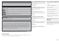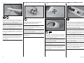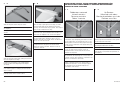
1
ARF ALMOST-READY-TO-FLY Allusive ™ 2.2m Instruction Manual Bedienungsanleitung Manuel d’utilisation Manuale di Istruzioni NOTICE SAFETY WARNINGS AND PRECAUTIONS SAFE OPERATING RECOMMENDATIONS All instructions, warranties and other collateral documents are subject to change at the sole discretion of Horizon Hobby, Inc. For up-to-date product literature, visit horizonhobby. com and click on the support tab for this product. Read and follow all instructions and safety precautions before use. Improper use can result in fire, serious injury and damage to property. • Inspect your model before every flight to ensure it is airworthy. Components Meaning of Special Language The following terms are used throughout the product literature to indicate various levels of potential harm when operating this product: NOTICE: Procedures, which if not properly followed, create a possibility of physical property damage AND a little or no possibility of injury. CAUTION: Procedures, which if not properly followed, create the probability of physical property damage AND a possibility of serious injury. WARNING: Procedures, which if not properly followed, create the probability of property damage, collateral damage, and serious injury OR create a high probability of superficial injury. WARNING: Read the ENTIRE instruction manual to become familiar with the features of the product before operating. Failure to operate the product correctly can result in damage to the product, personal property and cause serious injury. Use only with compatible components. Should any compatibility questions exist, please refer to the product instructions, component instructions or contact the appropriate Horizon Hobby office. Flight Fly only in open areas to ensure safety. It is recommended flying be done at radio control flying fields. Consult local ordinances before choosing a flying location. • Always be courteous and respectful of other users in your selected flight area. • Choose an area clear of obstacles and large enough to safely accomodate your flying activity. • Make sure this area is clear of friends and spectators prior to launching your aircraft. • Be aware of other activities in the vicinity of your flight path that could cause potential conflict. Propeller • Carefully plan your flight path prior to launch. Keep loose items that can become entangled in the propeller away from the prop. This includes loose clothing or other objects such as pencils and screwdrivers. Keep your hands away from the propeller as injury can occur. • Abide by any and all established AMA National Model Aircraft Safety Code. Batteries This is a sophisticated hobby product. It must be operated with caution and common sense and requires some basic mechanical ability. Failure to operate this Product in a safe and responsible manner could result in injury or damage to the product or other property. This product is not intended for use by children without direct adult supervision. Do not use with incompatible components or alter this product in any way outside of the instructions provided by Horizon Hobby, Inc. This manual contains instructions for safety, operation and maintenance. It is essential to read and follow all the instructions and warnings in the manual, prior to assembly, setup or use, in order to operate correctly and avoid damage or serious injury. • Be aware of any other radio frequency user who may present an interference problem. Always follow the manufacturer’s instructions when using and disposing of any batteries. Mishandling of Li-Po batteries can result in fire causing serious injury and damage. Small Parts REGARDING MOTOR AND BATTERY SELECTION This model has been tested using the components listed in the Power Systems section of this manual. Using components that exceed the output of the listed components may place excessive loads on the airframe. This could result in the failure of the airframe in highspeed or high-load situations. This kit includes small parts and should not be left unattended near children as choking and serious injury could result. Age Recommendation: Not for children under 14 years. This is not a toy. USING THE MANUAL This manual is divided into sections to help make assembly easier to understand. Boxes () have been placed next to each step. These help keep track of steps that have been completed. 2 EFL Allusive 2.2m HINWEIS Alle Anweisungen, Garantien und anderen zugehörigen Dokumente können im eigenen Ermessen von Horizon Hobby, Inc. jederzeit geändert werden. Die aktuelle Produktliteratur finden Sie auf horizonhobby.com unter der Registerkarte „Support“ für das betreffende Produkt. Spezielle Bedeutungen Die folgenden Begriffe werden in der gesamten Produktliteratur verwendet, um auf unterschiedlich hohe Gefahrenrisiken beim Betrieb dieses Produkts hinzuweisen: HINWEIS: Wenn diese Verfahren nicht korrekt befolgt werden, können sich möglicherweise Sachschäden UND geringe oder keine Gefahr von Verletzungen ergeben. ACHTUNG: Wenn diese Verfahren nicht korrekt befolgt werden, ergeben sich wahrscheinlich Sachschäden UND WARNUNGEN UND SICHERHEITSVORKEHRUNGEN EMPFEHLUNGEN ZUM SICHEREN BETRIEB Bitte lesen und befolgen Sie alle Anweisungen und Sichervorkehrungen vor dem Gebrauch. Falscher, nicht sachgemäßer Gebrauch kann Feuer, ernsthafte Verletzungen und Sachbeschädigungen zur Folge haben. • Überprüfen Sie zur Flugtauglichkeit ihr Modell vor jedem Flug. Komponenten Verwenden Sie mit dem Produkt nur kompatible Komponenten. Sollten Fragen zur Kompatibilität auftreten, lesen Sie bitte die Produkt- oder Bedienungsanweisung oder kontaktieren den Service von Horizon Hobby. die Gefahr von schweren Verletzungen. Fliegen WARNUNG: Wenn diese Verfahren nicht korrekt befolgt werden, ergeben sich wahrscheinlich Sachschäden, Kollateralschäden und schwere Verletzungen ODER mit hoher Wahrscheinlichkeit oberflächliche Verletzungen. Fliegen Sie um Sicherheit garantieren zu können, nur in weiten offenen Gegenden. Wir empfehlen hier den Betrieb auf zugelassenen Modellflugplätzen. Bitte beachten Sie lokale Vorschriften und Gesetze, bevor Sie einen Platz zum Fliegen wählen. WARNUNG: Lesen Sie die GESAMTE Bedienungsanleitung, um sich vor dem Betrieb mit den Produktfunktionen vertraut zu machen. Wird das Produkt nicht korrekt betrieben, kann dies zu Schäden am Produkt oder persönlichem Eigentum führen oder schwere Verletzungen verursachen. Dies ist ein hochentwickeltes Hobby-Produkt. Es muss mit Vorsicht und gesundem Menschenverstand betrieben werden und benötigt gewisse mechanische Grundfähigkeiten. Wird dieses Produkt nicht auf eine sichere und verantwortungsvolle Weise betrieben, kann dies zu Verletzungen oder Schäden am Produkt oder anderen Sachwerten führen. Dieses Produkt eignet sich nicht für die Verwendung durch Kinder ohne direkte Überwachung eines Erwachsenen. Verwenden Sie das Produkt nicht mit inkompatiblen Komponenten oder verändern es in jedweder Art ausserhalb der von Horizon Hobby, Inc. vorgegebenen Anweisungen. Diese Bedienungsanleitung enthält Anweisungen für Sicherheit, Betrieb und Wartung. Es ist unbedingt notwendig, vor Zusammenbau, Einrichtung oder Verwendung alle Anweisungen und Warnhinweise im Handbuch zu lesen und zu befolgen, damit es bestimmungsgemäß betrieben werden kann und Schäden oder schwere Verletzungen vermieden werden. Nicht geeignet für Kinder unter 14 Jahren. Dies ist kein Spielzeug. Propeller Halten Sie lose Gegenstände die sich im Propeller verfangen können weg vom Propeller. Dieses gilt auch für Kleidung oder andere Objekte wie zum Beispiel Stifte oder Schraubendreher. Halten Sie ihre Hände weg vom Propeller, es besteht akute Verletzungsgefahr. Akkus • Beachten Sie andere Piloten deren Sendefrequenzen ihre Frequenz stören könnte. • Begegnen Sie anderen Piloten in ihrem Fluggebiet immer höflich und respektvoll. • Wählen Sie ein Fluggebiet, dass frei von Hindernissen und groß genug ist. • Stellen Sie vor dem Start sicher, dass die Fläche frei von Freunden und Zuschauern ist. • Beobachten Sie den Luftraum und andere Flugzeuge/ Objekte die ihren Flugweg kreuzen und zu einem Konflikt führen könnten. • Planen Sie sorgfältig ihren Flugweg vor dem Start. MOTOR- UND AKKUAUSWAHL Dieses Modell wurde mit den Komponenten getestet die in dem Kapitel Antriebe aufgeführt sind. Sollten Sie Komponenten verwenden die nicht aufgeführt sind, könnte dieses zu einer erheblichen Belastung des Rumpfes führen. Das könnte zu einem Versagen des Rumpfes bei hohen Geschwindigkeiten oder bei starken Belastungen führen. Folgen Sie immer den Herstelleranweisungen bei dem Gebrauch oder Entsorgung von Akkus. Falsche Behandlung von Li-Po Akkus kann zu Feuer mit Körperverletzungen und Sachbeschädigung führen. Kleinteile Dieser Baukasten beinhaltet Kleinteile und darf nicht unbeobachtet in der Nähe von Kindern gelassen werden, da die Teile verschluckt werden könnten mit ernsthaften Verletzung zur Folge. ÜBER DIESE ANLEITUNG Diese Anleitung ist zur Vereinfachung des Zusammenbaues in Sektionen unterteilt. Neben den Sektionen befinden sich Kästchen () die es Ihnen leichter machen den Arbeitsschritt als erledigt abzuhaken. EFL Allusive 2.2m 3 REMARQUE La totalité des instructions, garanties et autres documents est sujette à modification à la seule discrétion d’Horizon Hobby, Inc. Pour obtenir la documentation à jour, rendez-vous sur le site horizonhobby.com et cliquez sur l’onglet de support de ce produit. Signification de certains termes spécifiques Les termes suivants sont utilisés dans l’ensemble du manuel pour indiquer différents niveaux de danger lors de l’utilisation de ce produit: AVERTISSEMENTS RELATIFS À LA SÉCURITÉ CONSIGNES DE SÉCURITÉ CONCERNANT L’UTILISATION Lisez et suivez toutes les instructions relatives à la sécurité avant utilisation. Une utilisation inappropriée peut entraîner un incendie, de graves blessures et des dégâts matériels. • Inspectez votre modèle avant chaque vol. Composants REMARQUE: Procédures qui, si elles ne sont pas suivies correctement, peuvent entraîner des dégâts matériels ET éventuellement un faible risque de blessures. Utilisez uniquement des composants compatibles. Si vous avez des questions concernant la compatibilité, référez-vous à ce manuel ou contactez le service technique Horizon Hobby. ATTENTION: Procédures qui, si elles ne sont pas suivies correctement, peuvent entraîner des dégâts Le vol matériels ET des blessures graves. AVERTISSEMENT: Procédures qui, si elles ne sont pas suivies correctement, peuvent entraîner des dégâts matériels et des blessures graves OU engendrer une probabilité élevée de blessure superficielle. Volez uniquement dans des zones dégagées pour un maximum de sécurité. Il est recommandé d’utiliser les pistes des clubs d’aéromodélisme. Consultez votre mairie pour connaître les sites autorisés. L’hélice AVERTISSEMENT: Lisez la TOTALITÉ du manuel d’utilisation afin de vous familiariser avec les caractéristiques du produit avant de le faire fonctionner. Une utilisation incorrecte du produit peut entraîner sa détérioration, ainsi que des risques de dégâts matériels, voire de blessures graves. Gardez éloignés tous les éléments qui pourraient être attrapés par l’hélice. Cela inclut les vêtements larges ou les objets comme des outils par exemple. Gardez toujours vos mains à distance pour éviter tout cas de blessures. Les batteries Ceci est un produit de loisirs sophistiqué. Il doit être manipulé avec prudence et bon sens et requiert des aptitudes de base en mécanique. Toute utilisation irresponsable de ce produit ne respectant pas les principes de sécurité peut provoquer des blessures, entraîner des dégâts matériels et endommager le produit. Ce produit n’est pas destiné à être utilisé par des enfants sans la surveillance directe d’un adulte. N’essayez pas de modifier ou d’utiliser ce produit avec des composants incompatibles hors des instructions fournies par Horizon Hobby, Inc. Ce manuel comporte des instructions relatives à la sécurité, au fonctionnement et à l’entretien. Il est capital de lire et de respecter la totalité des instructions et avertissements du manuel avant l’assemblage, le réglage et l’utilisation, ceci afin de manipuler correctement l’appareil et d’éviter tout dégât matériel ou toute blessure grave. Suivez toujours les instructions du fabricant de vos batteries. Une mauvaise manipulation d’une batterie LiPo peut entraîner un incendie causant de graves dégâts matériels et des blessures corporelles. • Surveillez les fréquences utilisées à proximité. • Soyez toujours courtois et respectueux des autres utilisateurs de la zone de vol. • Choisissez une zone dégagée de tout obstacle et suffisamment grande pour voler en toute sécurité. • Contrôlez que la zone est libre de spectateurs avant de lancer votre modèle. • Soyez conscient des autres activités aux alentours de votre vol, pour éviter tout conflit potentiel. • Planifiez votre vol avant de le commencer. SÉLECTION DE LA BATTERIE ET DU MOTEUR Ce modèle a été testé avec les éléments cités dans la section relative à la motorisation de ce manuel. L’utilisation d’éléments supérieurs à ceux présentés dans ce manuel peuvent générer des contraintes trop importantes sur la structure. Cela peut causer une rupture de la structure à haute vitesse ou lors de ressources. Petites pièces Ce kit contient des petites pièces qui ne doivent pas être laissées à la portée des enfants, ces pièces sont dangereuses pour eux et peuvent entraîner de graves blessures. 14 ans et plus. Ceci n’est pas un jouet. UTILISATION DU MANUEL Ce manuel est divisé en sections pour vous aider à comprendre plus facilement l’assemblage. Des cases () ont été placées à chaque étape. Cela vous permet d’avoir un suivi des étapes déjà effectuées. 4 EFL Allusive 2.2m AVVISO Tutte le istruzioni, le garanzie e gli altri documenti pertinenti sono soggetti a cambiamenti a totale discrezione di Horizon Hobby, Inc. Per una documentazione aggiornata sul prodotto, visitare il sito www.horizonhobby.com e fare clic sulla sezione Support per questo prodotto. Significato dei termini particolari In tutta la documentazione relativa al prodotto sono utilizzati i seguenti termini per indicare vari livelli di potenziale pericolo durante il funzionamento: AVVISO: Procedure che, se non sono seguite correttamente, possono creare danni materiali E nessuna o scarsa possibilità di lesioni. ATTENZIONE: Procedure che, se non sono seguite correttamente, possono creare danni materiali E possibili gravi lesioni. AVVERTENZA: Procedure che, se non debitamente seguite, espongono alla possibilità di danni alla proprietà fisica o possono omportare un’elevata possibilità di provocare ferite superficiali. Ulteriori precauzioni per la sicurezza e avvertenze. AVVERTENZA: Leggere TUTTO il manuale di istruzioni e prendere familiarità con le caratteristiche del prodotto, prima di farlo funzionare. Un utilizzo scorretto del prodotto può causare danni al prodotto stesso, alle persone o alle cose, provocando gravi lesioni. AVVERTIMENTI E PRECAUZIONI PER LA SICUREZZA RACCOMANDAZIONI PER OPERARE IN SICUREZZA Prima dell’uso leggere attentamente tutte le istruzioni e le precauzioni per la sicurezza. In caso contrario si potrebbero procurare incendi, danni o ferite. • Controllare attentamente il modello prima di ogni volo per accertarsi che sia idoneo. Componenti Usare solo componenti compatibili. Se ci fossero dubbi riguardo alla compatibilità, è opportuno far riferimento alle istruzioni relative al prodotto o ai componenti oppure rivolgersi al reparto Horizon Hobby di competenza. Volo Per sicurezza volare solo in aree molto ampie. Meglio se si va su campi volo autorizzati per modellismo. Consultare le ordinanze locali prima di scegliere una ubicazione. Elica Tenere gli oggetti liberi (vestiti, penne, cacciaviti, ecc.) lontano dall’elica, prima che vi restino impigliati. Bisogna fare attenzione anche con le mani perché c’è il rischio di ferirsi anche gravemente. Batterie Questo è un prodotto di hobbistica sofisticato e NON un giocattolo. È necessario farlo funzionare con cautela e responsabilità e avere conoscenze basilari di meccanica. Se questo prodotto non è utilizzato in maniera sicura e responsabile potrebbero verificarsi lesioni o danni al prodotto stesso o ad altre proprietà. Non è un prodotto adatto a essere utilizzato dai bambini senza la diretta supervisione di un adulto. Non usare componenti non compatibili o alterare il prodotto in nessuna maniera al di fuori delle istruzioni fornite da Horizon Hobby, Inc. Questo manuale contiene le istruzioni per un funzionamento e una manutenzione sicuri. È fondamentale leggere e seguire tutte le istruzioni e le avvertenze del manuale prima di montare, configurare o far funzionare il Prodotto, al fine di utilizzarlo correttamente e di evitare danni o lesioni gravi. Quando si maneggiano o si utilizzano le batterie, bisogna attenersi alle istruzioni del costruttore; il rischio è di procurare incendi, specialmente con le batterie Li-Po, con danni e ferite serie. Piccole parti Questo kit comprende delle parti di piccole dimensioni e non lo si può lasciare incustodito se c’è la presenza di bambini che li possono inghiottire e rimanere soffocati o intossicati. • Essere consapevoli che un altro utente della frequenza in uso, potrebbe procurare delle interferenze. • Essere sempre cortesi e rispettosi nei confronti degli altri utilizzatori dell’area in cui ci si trova. • Scegliere un’area libera da ostacoli e abbastanza ampia da permettere lo svolgimento del volo in sicurezza. • Prima del volo verificare che l’area sia libera da amici e spettatori. • Stare attenti alle altre attività che si svolgono in vicinanza della vostra traiettoria di volo, per evitare possibili conflitti. • Pianificare attentamente il volo prima di lanciare il modello. • Rispettare sempre scrupolosamente le regole stabilite dall’associazione locale. RIGUARDO ALLA SCELTA DI MOTORE E BATTERIA Questo modello è stato provato usando i componenti elencati nella sezione “Sistema di propulsione” di questo manuale. Usando componenti all’infuori di quell’elenco, si potrebbe dare un carico eccessivo alla struttura. Questo potrebbe causare delle rotture ad alta velocità e in situazioni con cariche elevati. Almeno 14 anni. Non è un giocattolo. COME USARE IL MANUALE Questo manuale è diviso in sezioni per rendere più facile la comprensione del montaggio. Vicino ad ogni passo sono stati posti dei piccoli quadrati () per aiutare a tenere traccia delle cose fatte e di quelle da fare. EFL Allusive 2.2m 5 SPECIFICATIONS•SPEZIFIKATIONEN• SPÉCIFICATIONS•SPECIFICHE LARGE PARTS LAYOUT•BAUTEILE (OHNE KLEINTEILE)•GRANDES PIÈCES•SCHEMA DEI COMPONENTI GRANDI 87.5 in (2.20m) 4 4 546 sq in (35.2 dm2) 2 3 1 43.0 in (1.10m) 48.0 oz (1.40 kg) Electric Power Power: Power 15 Brushless Elektro Antrieb Power: Power 15 Brushless Moteur électrique (EP): Power 15 Brushless Motore elettrico: Power 15 Brushless 6 5 4-channel (or greater) with 4 servos with V-Tail mixing capability 4-Kanal (oder größer) mit 4 Servos mit V-Leitwerksmischer 4 voies (ou plus) avec 4 servos avec mixage pour empennage en V a 4 canali (o più) con 4 servo e con miscelazione per la coda a V 5 5 5 6 7 ASSEMBLY SYMBOL GUIDE•MONTAGE SYMBOLE•GUIDE DES SYMBOLES POUR ASSEMBLAGE•GUIDA AI SIMBOLI DI ASSEMBLAGGIO Apply threadlock Schraubensicherungslack verwenden Utilisez du frein filet Applicare fuido threadlock Use thin CA Dünnflüssigen Sekundenkleber verwenden Utilisez de la colle cyanoacrylate fine Usare colla ciano acrilica fine LL RR Assemble right and left Use 5-minute epoxy Fully tighten Verwenden Sie 5 Minuten Epoxy Vollständig festziehen/festschrauben Utilisez de l’époxy 5 minutes Serrez complètement Assemblare destra e sinistra Usare una resina epossidica con indurimento di 5 minuti Stringere al massimo Use hobby knife with #11 blade Use a felt-tipped pen Ensure free rotation Verwenden Sie einen Faserstift Rotation sicherstellen Utilisez un feutre fin effaçable Permettez une rotation libre Usare un pennarello Assicurarsi rotazione libera Links und rechts montieren Assemblez à droite et à gauche Verwenden Sie ein Hobbymesser mit # 11 Klinge Utilisez un Couteau: Lame numéro 11 15 Usare taglierino per hobbistica con lama numero 11 6 EFL Allusive 2.2m REPLACEMENT PARTS•ERSATZTEILE•PIÈCES DE RECHANGE•RICAMBI Part English Deutsch Français Italiano 1. EFL492501 Right Wing Panel Tragfläche rechts Aile droite Semiala destra 2. EFL492502 Left Wing Panel Tragfläche links Aile gauche Semiala sinistra 3. EFL492503 Fuselage Rumpf Fuselage Fusoliera 4. EFL492504 Stabilizer Set Leitwerksset Stabilisateurs Set stabilizzatore 5. EFL492505 Hardware Pack Kleinteilepaket Sachet d’accessoires Viti e accessori 6. EFL492506 Wing Rod Set Flächenverbinder Set de clés d’aile Set baionette ala 7. EFL492507 Canopy Kabinenhaube Verrière Calotta REQUIRED RADIO EQUIPMENT•ERFORDERLICHE RC AUSRÜSTUNG•EQUIPEMENT RADIO REQUIS•APPARECCHIATURE RADIO SPMAR6260 AR6260 DSMX® 6-Channel Carbon Fuselage Receiver AR6260 DSMX® 6-Kanal Carbon Rumpf Empfänger Récepteur AR6260 6 voies DSMX pour fuselage carbone AR6260 DSMX ricevitore 6 canali per fusoliera in carbonio SPMSA5030 (2) A5030 Mini Digital Aicraft Servo Spektrum A5030 Mini Digital Flug -Servo Mini-servo numérique A5030 pour aéronefs Servo digitale mini A5030 per aeromodelli SPMSA7020 (2) A7020 Digital Wing Servo A7020 digitales Tragflächenservo Servo A7020 Digital pour aile A7020 servo digitale per ala SPMA3051 (2) Standard Servo Extension, 6-inch Spektrum Servokabelverlängerung 150mm Rallonge servo standard, 150mm Prolunga standard per servo, 150mm SPMA3004 (2) Standard Servo Extension, 18-inch Spektrum Servokabelverlängerung 460mm Rallonge servo standard, 460mm Prolunga standard per servo, 460mm POWER SYSTEM•ANTRIEB•MOTORISATION•SISTEMA PROPULSIVO EFLM4015A Power 15 Brushless Outrunner Motor, 950Kv Power 15 Brushless Außenläufer Motor, 950Kv Moteur Power 15 brushless à cage tournante, 950Kv Power 15 motore brushless a cassa rotante, 950Kv EFLA1040LB 40-Amp Lite Pro SB Brushless ESC (V2) 40A Lite Pro SB Brushless ESC (V2) Contrôleur brushless 40A Lite Pro (V2) 40-Amp Lite Pro SB Brushless ESC (V2) EFLB22003S30 2200mAh 3S 11.1V 30C Li-Po 2200mAh 3S 11.1V 30C Li-Po Batterie Li-Po 3S 11.1V 2200mA 2200mAh 3S 11.1V 30C Li-Po EFLP12080PP Plastic Propeller, 12 x 8 Kunststoff Propeller, 12 x 8 Hélice plastique 12x8 Elica in plastica, 12 x 8 EFLP12080S Spinner Assembly Spinner Cône + moyeu Gruppo ogiva REQUIRED ADHESIVES•ERFORDERLICHE KLEBSTOFFE•TYPES DE COLLES•ADESIVI NECESSARI PAAPT09 Thin CA Sekundenkleber dünnflüssig Colle cyano fine Sottile CA PAAPT35 15-Minute Epoxy 15 Minuten Epoxy Époxy 15 minutes Colla epoxy 15 minuti OPTIONAL ITEMS•OPTIONALE TEILE•ELÉMENTS OPTIONNELS•ARTICOLI OPZIONALI EFLP12080CP Carbon Propeller, 12 x 8 Carbon Propeller, 12 x 8 Hélice carbone 12x8 Elica in carbonio, 12 x 8 EFLA110 Power Meter E-flite Lastmessgerät Wattmètre Misuratore di potenza EFLC3020 Celectra™ 200W DC Charger E-flite 200W DC Multi-Akku Ladegerät Chargeur CC 200W Celectra Celectra 200W DC Caricabatterie EFL Allusive 2.2m 7 REQUIRED TOOLS•BENÖTIGTES WERKZEUG•OUTILS REQUIS•ATTREZZI NECESSARI English Deutsch Français Italiano Box wrench: 12mm Ringschlüssel: 12mm Clé plate fermée 12mm Chiave a tubo: 12mm Clear tape Transparentes Klebeband Adhésif transparent Nastro trasparente Drill bit: 1/16-inch, 5/64-inch Bohrer: 1,5 mm, 2mm Foret : 1,5 mm, 2mm Punte per trapano: 1,5 mm, 2mm Electrical tape-white Isolierband weiss Ruban adhésif d’électricien blanc Nastro elettrico bianco Felt-tipped pen Faserstift Feutre fin effaçable Pennarello Hemostat Klemme Pince Hemostat Pinzetta Hex wrench: 1/16-inch Inbusschlüssel: 1/16-inch Tournevis hexagonal : 1/16-inch Chiave esag.: 1/16-inch Hobby knife: #11 blade Hobbymesser mit # 11 Klinge Couteau : Lame numéro 11 Taglierino: #11 lama Phillips screwdriver: #1 Phillips Schraubendreher: #1 Tournevis cruciforme: #1 Cacciavite a croce: #1 Pin vise Handbohrer Porte-forets Trapano manuale Pliers Zange Pince Pinze Ruler Lineal Réglet Righello Sandpaper Schleifpapier Papier de verre Carta vetrata Scissors Schere Ciseaux Forbici Side cutters Seitenschneider Pince coupante Lama laterale Toothpicks Zahnstocher Cure dents Stuzzicadenti FASTENERS•VERBINDUNGSELEMENTE•ATTACHES•ELEMENTI DI FISSAGGIO Hex Nut Sechskantmutter Ecrou hexagonal Dado esagonale 8 M Metal Clevis Gabelkopf Chape métallique Forcella metallica Washer-Head Machine Screw Breitkopf- Maschinenschraube Vis à tête épaulée Vite per metallo con rondella EFL Allusive 2.2m BEFORE STARTING ASSEMBLY VOR DEM ZUSAMMENBAU • Remove parts from bag. • Entnehmen Sie zur Überprüfung jedes Teil der Verpackung. • Inspect fuselage, wing panels, rudder and stabilizer for damage. • If you find damaged or missing parts, contact your place of purchase. If you find any wrinkles in the covering, use a heat gun (HAN100) and covering glove (HAN150) or covering iron (HAN101) with a sealing iron sock (HAN141) to remove them. Use caution while working around areas where the colors overlap to prevent separating the colors. This model has been designed to keep the weight at a minimum. When tightening the covering, work carefully to avoid inducing warps or changing the alignment of the structure. • Überprüfen Sie den Rumpf, Tragflächen, Seiten- und Höhenruder auf Beschädigung. • Sollten Sie beschädigte oder fehlende Teile feststellen, kontaktieren Sie bitte den Verkäufer. Zum Entfernen von Falten in der Bespannung verwenden Sie den Heißluftfön (HAN100) und Bespannhandschuh (HAN150) oder das Folienbügeleisen (HAN141). Bitte achten Sie bei überlappenden Farben, dass Sie diese sich bei dem Bearbeitung nicht trennen. Dieses Modell wurde auf geringstes Gewicht konstruiert. Bitte beachten Sie bei dem Spannen der Bespannfolie, dass sie nicht die Ausrichtung der Struktur verändern. AVANT DE COMMENCER L’ASSEMBLAGE • Retirez toutes les pièces des sachets pour les inspecter. • Inspectez soigneusement le fuselage, les ailes et les empennages. • Si un élément est endommagé, contactez votre revendeur. Si l’entoilage présente des plis, vous pouvez les lisser en utilisant le pistolet à air chaud (HAN100) et le gant (HAN150) ou le fer à entoiler (HAN101) avec la chaussette de protection (HAN141). Agissez soigneusement dans les zones où plusieurs couleurs d’entoilage sont superposées afin d’éviter de les séparer. PRIMA DI INIZIARE IL MONTAGGIO • Togliere tutti i pezzi dalla scatola. • Verificare che la fusoliera, l’ala e i piani di coda non siano danneggiati. • Se si trovano parti danneggiate, contattare il negozio da cui è stato acquistato. Se si trovano delle pieghe nella ricopertura, si possono togliere usando una pistola ad aria calda (HAN100) e guanto per ricopertura (HAN150), oppure un ferro per ricopertura (HAN101) con la sua calza di protezione (HAN141). Usare cautela quando si lavora in aree del rivestimento dove ci sono dei colori sovrapposti, per evitare la loro separazione. Questo modello è stato progettato per mantenere al minimo il suo peso. Quando si tende il rivestimento, bisogna lavorare con attenzione per non fare delle grinze o modificare l’allineamento delle strutture (svergolature). • Charge transmitter and receiver batteries. • Laden des Senders und Empfängers. Ce modèle a été conçu pour obtenir une masse minimale. Quand vous retendez l’entoilage, prenez soin de ne pas déformer la structure. • Center trims and sticks on your transmitter. • Zentrieren der Trimmungen und Sticks auf dem Sender. • ll est recommandé de préparer tous les éléments du système de la radio. • Sollten Sie einen Computersender verwenden, resetten Sie einen Speicherplatz und benennen ihn nach dem Modell. • Cela inclut, la charge des batteries comme la mise au neutre des trims et des manches de votre émetteur. • Sender und Empfänger jetzt nach den Bindeanweisung des Herstellers zu binden. • Si vous utilisez une radio programmable, sélectionnez une mémoire libre afin d’y enregistrer les paramètres de ce modèle. • Facendo riferimento alle istruzioni del radiocomando, connettere (bind) trasmettitore e ricevitore. • Nous vous recommandons d’affecter maintenant le récepteur à l’émetteur en suivant les instructions fournies avec votre radio. IMPORTANTE: Ripetere la procedura di connessione una volta regolate le corse, per evitare che i servi vadano a fine corsa. Garantirà anche che le impostazioni di inversione del servo vengano salvate nel sistema radio. • For a computer radio, create a model memory for this particular model. • Bind your transmitter and receiver, using your radio system’s instructions. IMPORTANT: Rebind the radio system once all control throws are set. This will keep the servos from moving to their endpoints until the transmitter and receiver connect. It will also guarantee the servo reversal settings are saved in the radio system. EFL Allusive 2.2m WICHTIG: Wir empfehlen dringend nachdem alle Einstellungen vorgenommen worden sind, das Modell neu zu binden. Dieses verhindert, dass die Servos in die Endanschläge laufen bevor sich Sender und Empfänger verbunden haben. Es garantiert auch, dass die Servoreverseeinstellungen in der RC Anlage gesichert sind. • Caricare il trasmettitore e la batteria di volo. • Centrare stick e trim sul trasmettitore. • Con una radio computerizzata creare una nuova memoria per questo modello. IMPORTANT: Il est hautement recommandé de ré-affecter le système une fois que les courses seront réglées. Cela empêchera les servos d’aller en butée lors de la connexion du système. Cela garantit également que la direction des servos est enregistrée dans l’émetteur. 9 CONTROL HORN INSTALLATION•EINBAU DER RUDERHÖRNER•INSTALLATION DES GUIGNOLS•INSTALLAZIONE DELLE SQUADRETTE 1 2 3 4 LL RR 15 Aileron Control Horns• Querruderhörner•Guignol des ailerons•Squadrette per alettoni LL RR Ruddervator Control Horns• V-Leitwerkshörner•Guignols de stabilisateurs•Squadrette per coda a V Use sandpaper to lightly sand the bottom of the control horn where it fits into the control surface. Remove any dirt and oils from the control horn using a paper towel and isopropyl alcohol. Place low-tack tape so it is spaced 1/32 inch (1mm) from the base of the control horn. This will prevent epoxy from getting on the aileron surface when the control horn is glued in place. Schleifen Sie den Teil des Ruderhorns an der in das Ruder gesteckt wird. Entfernen Sie alle Verschmutzungen vom Ruderhorn mit einem Papiertuch und Reinigungsalkohol. Kleben Sie Kreppband mit 1mm Abstand zum Ruderhorn auf. Das verhindert dass Epoxy auf der Ruderfläche klebt wenn das Ruderhorn eingeklebt wird. Utilisez du papier abrasif pour poncer la partie basse du guignol qui entre dans la dérive. Retirez la poussière et les traces de lubrifiant en utilisant du papier absorbant et de l’alcool dénaturé. Carteggiare leggermente la parte inferiore delle squadrette, proprio dove entrano nella superficie di controllo. Pulirle da polvere ed olio usando un fazzoletto di carta e alcool isopropilico. Locate the aileron and ruddervator control horn. Note the ruddervator control horns do not have a hole where the horn fits into the control surface. Legen Sie die Querruder - und V-Leitwerkshörner bereit. Bitte beachten Sie, dass die V-Leitwerkshörner am Unterteil dass in die Tragfläche gesteckt wird. kein Loch haben. Repérez les guignols d’ailerons et de stabilisateur. Vous remarquerez que les guignols de stabilisateur n’ont pas de trou au niveau de leur base. Individuare le squadrette per alettoni e piani di coda a V, notando che quelle per i piani di coda a V non hanno il foro sulla parte che entra nella superficie di controllo. 10 Placez de l’adhésif de masquage à une distance de 1mm autour de la fente destinée au guignol. Cela permet d’éviter de mettre de la colle sur la surface de l’aileron quand le guignol est collé en place. Mettere del nastro a bassa adesività in modo che sia distanziato di 1mm dalla base della squadretta. Questo serve ad evitare che la colla epoxy esca dalla superficie di controllo quando si incolla la squadretta. Mix a small amount of 15-minute epoxy. Use a toothpick to apply epoxy in the slot for the control horn, and to the area of the control horn that fits into the aileron. Fit the control horn in the aileron. The horn will fit snug in the slot. Use a paper towel and isopropyl alcohol to remove any excess epoxy from around the control horn. Before the epoxy fully cures, remove the tape from around the control horn. Mischen Sie eine kleine Menge von 15 Minuten Epoxy und geben den Klebstoff mit einem Zahnstocher in den Schlitz und auf die Auflagefläche. Das Horn paßt saugend in den Schlitz. Wischen Sie überschüssigen Kleber mit einem Papiertuch und Reinigungsalkohol ab. Entfernen Sie das Klebeband bevor der Klebstoff vollständig getrocknet ist. Mélangez une petite quantité de colle époxy 15 minutes. Utilisez un cure-dent pour appliquer la colle Epoxy dans la fente destinée à recevoir le guignol. Insérez le guignol dans l’aileron. Le guignol doit être correctement ajusté. Utilisez du papier absorbant et de l’alcool dénaturé pour retirer l’excès de colle autour du guignol. Retirez l’adhésif de masquage avant le séchage total de la colle époxy. Miscelare una piccola quantità di colla epoxy 15 minuti. Con uno stuzzicadenti applicarla nelle fessure per le squadrette e sulla parte delle squadrette che entra negli alettoni. Le squadrette si inseriscono precise negli alettoni. Togliere gli eccessi di colla intorno alle squadrette con un fazzoletto di carta e alcool isopropilico. Prima che la colla sia asciutta, togliere il nastro messo prima intorno alle squadrette. EFL Allusive 2.2m 5 AILERON SERVO INSTALLATION•EINBAU DER QUERRUDERSERVOS• INSTALLATION DES SERVOS D’AILERONS•INSTALLAZIONE SERVO DELL’ALETTONE 1 3 2 LL RR 15 Repeat steps 3 and 4 to install the ruddervator control horns. LL RR LL RR Apply a small amount of thin CA to harden the threads made in the previous step. Wiederholen Sie die Schritte 3 und 4 um die V-Leitwerksruderhörner zu montieren. Use a pin vise and 1/16-inch (1.5mm) drill bit to enlarge the holes for the servo mounting screws. Thread a servo mounting screw into each hole to cut threads in the surrounding wood. Geben Sie einen kleinen Tropfen dünnflüssigen Sekundenkleber in die Gewindelöcher um diese zu härten. Répétez les étapes 3 et 4 pour installer les guignols des stabilisateurs. Vergrößern Sie mit einem 1,5mm Handbohrer die Löcher für die Servoeinbauschrauben. Appliquer une petite quantité de colle cyano fine pour durcir les filetages faits lors de l’étape précédente. Ripetere i passi 3 e 4 per montare le squadrette dei piani di coda a V. Utilisez un porte foret muni d’un foret de 1.5mm pour agrandir les trous de fixation du servo. Drehen Sie in jede Bohrung eine ServoBefestigungsschraube, um ein Gewinde in das Holz zu schneiden. Forare con una punta da 1,5mm per le viti di fissaggio dei servi. EFL Allusive 2.2m Visser une vis de fixation de servo dans chaque trou pour créer un filetage dans le bois. Mettere una piccola quantità di colla CA nei fori, per indurire il filetto fatto nel passaggio precedente. Avvitare una vite per il montaggio dei servo in ciascun foro per eseguire dei filetti nel legno circostante. 11 4 LL RR 15 5 LL RR Use 15-minute epoxy to glue the servo mount into the wing. Space the mount so it is 1/16 inch (1.5mm) from the edge of the opening. The open end of the mount faces to the wing tip (1), and the notch for the servo lead (2) faces toward the leading edge of the wing. Secure an 18-inch (460mm) extension to the servo lead using string or dental floss. Kleben Sie mit 15 Minuten Epoxy den Servohalter in die Tragfläche. Richten Sie den Halter so aus, dass er 1,5mm von der Kante entfernt ist. Die Öffnung zeigt dabei dabei zur Flächenspitze (1) und die Kabelöffnung zur Vorderkante (2) der Tragfläche. Fixez une rallonge de 460mm à la prise du servo en utilisant de la ficelle. Utilisez de la colle époxy 15 minutes pour coller le support dans l’aile. Placez le support à une distance de 1.5mm de l’arrête de l’ouverture. La partie ouverte du support est orientée vers le saumon de l’aile (Flèche 1), et l’encoche de passage des câbles est orientée vers le bord d’attaque de l’aile (Flèche 2). Sichern Sie die 460mm lange Servokabelverlängerung mit festem Garn oder Zahnseide. Fissare al connettore del servo una prolunga da 460mm usando un pezzo di spago. 6 LL RR Center the servo using the radio system. Place the servo horn on the servo after removing any arms that may interfere with the operation of the servo. Enlarge the hole in the arm that is 3/8 inch (10mm) from the center of the arm using a pin vise and 1/16-inch (1.5mm) drill bit. Prepare the left and right aileron servos at this time. Zentrieren Sie die Servos mit der Fernsteuerung. Entfernen Sie vom dem Servoarm alle weiteren Arme die den Betrieb stören könnten. Vergrößern Sie das Loch im Servoarm das 10mm von der Mitte entfernt ist mit einem 1,5mm Bohrer. Bereiten Sie das rechte und linke Servo vor. Placez le servo au neutre en utilisant la radio. Coupez les 3 parties inutilisées du palonnier qui pourraient interférer dans le mouvement du servo, puis placez le palonnier sur le servo. Utilisez un foret de 1.5mm pour agrandir le trou se situant à 10mm du centre. Préparez le servo de l’aileron gauche et celui de l’aileron droit durant cette étape. Centrare il servo con il radiocomando. Montare sul servo la sua squadretta dopo aver tolto i bracci che non servono perché potrebbero interferire con i movimenti. Con una punta da 1,5mm allargare il foro che si trova a 10mm dal centro della squadretta. A questo punto si possono preparare i servi per l’alettone destro e sinistro. Usare colla 15 minuti per incollare all’ala il supporto servo. Posizionare il supporto ad 1,5mm dal bordo dell’apertura. Il lato aperto del supporto è rivolto verso l’estremità dell’ala (1), e l’intaglio per il filo del servo (2) è rivolto verso il bordo di entrata dell’ala. 12 EFL Allusive 2.2m 7 LL RR Tie the string located inside the wing around the end of the servo extension. Wrap a piece of low-tack tape around the end, and form it into a point. This will guide the end of the extension easily through the wing. Knoten Sie die Schnur aus der Tragfläche um die Servoverlängerung. Wickeln Sie etwas Kreppband um das Ende und formen es zu einer Spitze. Das hilft dabei das Ende der Verlängerung durch die Tragfläche zu führen. Nouez la ficelle située dans l’aile autour de la rallonge de servo, entourez l’extrémité de la rallonge d’adhésif de masquage. Cela vous permettra de glisser facilement la rallonge dans l’aile. 8 LL RR Use the string to pull the extension through the wing. The tape can be removed once the extension is through the wing. Ziehen Sie mit der Schnur die Verlängerung durch die Tragfläche. Danach können Sie das Kreppband wieder abnehmen. Tirez sur la ficelle pour tirer la rallonge à travers l’aile. Retirez l’adhésif de masquage une fois que la rallonge est sortie de l’aile. Usare lo spago per tirare la prolunga attraverso l’ala. Fatto questo si può togliere il nastro adesivo. 9 Legare lo spago collocato all’interno dell’ala al connettore della prolunga. Avvolgere del nastro a bassa adesività per arrotondare il terminale e poterlo far scorrere meglio all’interno dell’ala. LL RR 10 LL RR M2 M x2 x2 Use a 11/2-inch (38mm) pushrod and the hardware listed to assemble the aileron linkage. Adjust the clevis so the aileron is centered when the servo is centered using the radio system. Slide the retainer over the forks of the clevis to secure it to the control horn. Tighten the nut against the clevis. Montieren Sie die Anlenkung mit dem 38mm langen Gestänge. Justieren Sie den Gabelkopf so, dass das Querruder mit zentriertem Servo ebenfalls zentriert ist. Schieben Sie das Sicherungsgummi über die Gabeln und drehen die Mutter fest. Utilisez la tringlerie de 38mm et les accessoires listés pour assembler la commande de l’aileron. Réglez la chape de façon à centrer l’aileron quand le servo est au neutre. Glissez le morceau de durite sur les fourches de la chape pour sécuriser la liaison. Serrez l’écrou contre la chape. Usare un rinvio da 38mm con le sue forcelle per collegare il servo all’alettone. Regolare la forcella in modo che l’alettone sia centrato quando il servo viene centrato con il radiocomando. Far scorrere il fermo sulla forcella per bloccarla sulla squadretta. Stringere il dado contro la forcella. 11 LL RR Use hobby scissors to trim the aileron servo cover. The cover is attached to the wing using clear tape. Make sure the cover is trimmed and positioned so the linkage does not bind on the cover when the aileron servo is in operation. Schneiden Sie mit einer Hobbyschere die Querruderservoabdeckung zurecht und kleben diese mit klarem Klebeband fest. Bitte stellen Sie sicher, dass die Abdeckung korrekt positioniert ist und das Querruderservo im Betrieb nicht behindert. Utilisez des ciseaux à Lexan pour découper le carénage de servo d’aileron. Le carénage se fixe sur l’aile à l’aide de ruban adhésif transparent. Contrôlez que le carénage est correctement découpé et ajusté autour du passage de la tringlerie afin d’éviter tout risque de blocage durant le fonctionnement du servo. Rifilare il coperchio del servo alettoni con forbici da hobby e fissarlo all’ala con nastro adesivo trasparente. Verificare che nel movimento del servo non ci siano attriti con il coperchio. Secure the servo in the mount using the screws provided with the servo. Schrauben Sie das Servo mit den Schrauben aus dem Lieferumfang fest. Fixez le servo au support en utilisant les vis fournies avec le servo. Fissare il servo sul supporto usando le sue viti. EFL Allusive 2.2m 13 STABILIZER INSTALLATION•MONTAGE DES HÖHENRUDERS• INSTALLATION DU STABILISATEUR•INSTALLAZIONE DELLO STABILIZZATORE 1 3 2 15 LL RR Fit the remaining stabilizer to the fuselage. Once fit, remove the stabilizers and pins. Apply a small amount of epoxy on the pins and into the holes in the stabilizers. Place the pins in the stabilizers. Place a small amount of epoxy in the holes in the fuselage, then reposition the stabilizers so they fit tightly against the fuselage. Use a small piece of low-tack tape to hold the stabilizers against the fuselage until the epoxy fully cures. Use a paper towel and isopropyl alcohol to remove any excess epoxy before it cures. Slide the two stabilizer pins into the stabilizer sockets. Schieben Sie die beiden Leitwerksstifte in das Leitwerk. Setzen Sie die zweite Leitwerkshälfte in den Rumpf. Ist diese ausgerichtet nehmen Sie beide heraus. Geben Sie eine kleine Epoxy Menge auf die Stifte und in die Öffnungen im Leitwerk. Setzen Sie die Stifte in das Leitwerk. Geben Sie eine kleine Menge Epoxy in die Löcher im Rumpf und passen dann das Leitwerk an den Rumpf an, so dass es sauber am Rumpf ansitzt. Sichern Sie das Leitwerk mit Kreppband bis der Klebstoff vollständig ausgehärtet ist. Wischen Sie überschüssigen Klebstoff mit einem Papiertuch und Isopropylalkhohol weg bevor der Kleber getrocknet ist. Glissez les 2 clés dans les fourreaux des stabilisateurs. Inserire le due baionette dello stabilizzatore nelle loro sedi. LL RR Fit the stabilizer to the fuselage with the control horn facing the top of the fuselage. Schieben Sie das Leitwerk in den Rumpf. Die Ruderhörner zeigen dabei nach oben. Glissez le deuxième stabilisateur dans le fuselage. Retirez les deux stabilisateurs. Appliquez de la colle époxy dans les fourreaux des stabilisateurs pour coller les clés. Appliquez de la colle époxy dans les trous du fuselage, puis repositionnez les stabilisateurs sur le fuselage, ils doivent être parfaitement plaqués contre le fuselage. Utilisez de l’adhésif de masquage pour maintenir les stabilisateurs en position durant le séchage de la colle époxy. Allineare anche l’altro stabilizzatore alla fusoliera. Fatto questo togliere gli stabilizzatori e le loro baionette. Mettere un po’ di colla epoxy sulla baionetta e nella sua sede sullo stabilizzatore e poi riposizionare il tutto allineandolo alla fusoliera. Usare un pezzettino di nastro a bassa adesività per tenere lo stabilizzatore contro la fusoliera intanto che la colla si asciuga. Con un fazzoletto di carta e alcool isopropilico togliere gli eccessi di colla prima che si indurisca. Glissez le stabilisateur dans le fuselage, le guignol doit être orienté vers le dessus du fuselage. Allineare uno stabilizzatore alla fusoliera con la squadretta rivolta verso l’alto. 14 EFL Allusive 2.2m SERVO INSTALLATION•SERVOEINBAU•INSTALLATION DES SERVOS•INSTALLAZIONE SERVO 1 Use the radio system to center the ruddervator servos. Install the servo arm on the servo, trimming it so it won’t interfere with the side of the fuselage when installed. The linkage will connect to the hole of the arm that is 5/16 inch (8mm) from the center of the servo. Zentrieren Sie das Leitwerk mit der Fernsteuerung . Setzen Sie den Arm auf das Servo auf und schneiden den Arm so zurecht, dass er im Rumpf ohne Behinderung laufen kann. Das Gestänge wird an das Loch angeschlossen dass 8mm von der Mitte entfernt ist. Utilisez la radio pour placer les servos au neutre. La tringlerie sera reliée au trou situé à une distance de 8mm du centre. Coupez le bras de servo de manière qu’il ne frotte pas le côté du fuselage durant son mouvement. Usare il radiocomando per centrare i servi dei piani di coda a V. Montare le squadrette sui servi tagliandole quanto basta in modo che non tocchino la fiancata della fusoliera. Il rinvio si collega al foro che sta a 8mm dal centro della squadretta. EFL Allusive 2.2m 2 Place the servo in the fuselage with the servo output facing the rear of the fuselage. Slide the servo as far to the side as possible, then mark the locations for the servo mounting screws. Setzen Sie das Servo in den Rumpf mit dem Abtrieb nach hinten ein. Schieben Sie das Servo so weit wie möglich nach rechts und markieren dann die Schraublöcher für die Servoschrauben. Placez le servo dans le fuselage, la tête du servo doit être orientée vers l’arrière du fuselage. Glissez le servo au maximum possible sur le côté, puis marquez les emplacements des vis de fixation. Mettere il servo nella fusoliera con l’albero di uscita rivolto verso la coda e il più distante possibile dalla fiancata. Poi segnare la posizione delle viti di fissaggio. 4 3 Use a pin vise and a 1/16-inch (1.5mm) drill bit to drill the holes for the servo mounting screws through the mounting plate. Bohren Sie mit einem 1,5mm Bohrer die Löcher für die Servoschrauben durch die Montageplatte. Utilisez un porte foret muni d’un foret de 1.5mm pour percer les trous de fixation des servos dans la platine. Con una punta da 1,5mm praticare sul sopporto i fori per le viti di fissaggio del servo. Thread a servo mounting screw into each hole to cut threads in the surrounding wood. Apply a small amount of thin CA to harden the threads made by the screws. Secure the servo in the fuselage using the screws provided with the servo. The output shaft of the servo faces toward the rear of the fuselage. Drehen Sie eine Servobefestigungsschraube in jedes Loch um ein Gewinde zu schneiden. Geben Sie dann einen Tropfen dünnflüssigen Sekundenkleber in das Loch um das Gewinde zu härten. Schrauben Sie dann das Servo mit den Schrauben aus dem Lieferumfang fest. Der Abtrieb des Servos zeigt dabei nach hinten zum Heck des Flugzeuges. Visser une vis de fixation de servo dans chacun des trous. Redevisser les vis et appliquez une goutte de colle CA pour durcir les filets. Fixez le servo dans le fuselage en utilisant les vis fournies avec le servo. La tête du servo doit être orientée vers l’arrière du fuselage. Avvitare una vite in ciascun foro e poi, dopo averla tolta, mettere un po’ di colla CA per indurire la filettatura fatta nel legno. Fissare il servo in fusoliera usando le sue viti. L’albero di uscita del servo deve essere rivolto verso la coda. 15 5 LINKAGE INSTALLATION•GESTÄNGEEINBAU•INSTALLATION DES TRINGLERIES•INSTALLAZIONE DEI RINVII Repeat steps 1 through 4 to install the remaining ruddervator servo. Wiederholen Sie die Schritte 1 bis 4 um das zweite V-Leitwerksservo einzubauen. Répétez les étapes de 1 à 4 pour installer le deuxième servo. Ripetere i passi da 1 a 4 per montare l’altro servo della coda. 16 2 1 M2 M x2 x2 LL RR Prepare the ruddervator pushrods by threading the nut and clevis on the brass fitting. Make sure the threads of the fitting can be seen between the forks of the clevis. Slide the pushrods into the pushrod tubes located inside the fuselage. Connect the clevises to the ruddervator control horns. Center the ruddervator control surface and ruddervator servo. Use a felt-tipped pen to mark the pushrod where it crosses the outer hole of the servo arm. Bereiten Sie das Gestänge durch aufdrehen das Gabelkopfes und der Mutter vor. Bitte achten Sie darauf, dass das Gewinde zwischen den Gabeln zu sehen ist. Schieben Sie das Gestänge in die Röhrchen im Rumpf. Schließen Sie dann die Gabelköpfe an die V-Leitwerksruder an. Zentrieren Sie die beiden V-Leitwerksservos. Markieren Sie das Gestänge mit einem Faserstift dort wo das äußere Loch den Servoarm kreuzt. Préparez les tringleries en vissant les chapes et les écrous sur l’embout en laiton. Vissez les chapes, l’extrémité de l’embout fileté doit tangenter le point de jonction des fourches de la chape. Glissez les tringleries dans les gaines situées dans le fuselage. Connectez les chapes aux guignols. Placez les gouvernes et les servos au neutre. Utilisez un feutre pour effectuer une marque sur la tringlerie à l’emplacement du trou du bras de servo. Preparare le barrette di rinvio per i comandi di coda avvitando i dadi e le forcelle sugli adattatori di ottone. Verificare che la parte filettata dell’adattatore si veda in mezzo alle forcelle. Inserire le barrette dei comandi nei loro tubetti guida già montati in fusoliera. Collegare le forcelle alle squadrette dei piani di coda. Centrare le superfici di controllo della coda e i servi ad esse collegati. Segnare le barrette nel punto in cui incrociano il foro esterno della squadretta del servo. EFL Allusive 2.2m 3 4 LL RR LL RR Disconnect the clevis from the ruddervator control horn. Use pliers to bend the pushrod 90 degrees at the mark made in the previous step. Trennen Sie den Gabelkopf vom Ruderhorn und biegen den Draht mit einer Zange 90° nach oben wo er das äußere Loch kreutzt. Déconnectez les chapes des guignols. Utilisez une pince pour couder la tringlerie à 90° au niveau de la marque précédemment tracée. Scollegare le forcelle dalle squadrette della coda. Piegare la barretta a 90° con una pinza nel punto segnato prima. 5 x2 Remove the servo arm from the servo. Use a pushrod connector to attach the pushrod to the servo arm. Nehmen Sie den Servoarm vom Servo ab und setzen den Sicherungsclip auf den Servoarm. Retirez le bras du servo. Utilisez un connecteur pour assurer la liaison de la tringlerie au bras de servo. Togliere la squadretta dal servo. Poi collegarle la barretta usando un apposito sistema di fissaggio (vedi figura). LL RR 6 Repeat steps 2 through 5 to connect the second ruddervator to the ruddervator servo. With the servo centered, reinstall the servo arm. Use the screw provided with the servo to secure the arm to the servo. Check to make sure the portion of the pushrod above the connector does not rub against the side of the fuselage. If it does, use side cutters to trim the excess wire. Wiederholen Sie die Schritte 2 bis 5 um das zweite Leitwerksservo anzuschließen. Setzen Sie den Arm auf das zentrierte Servo wieder auf und sichern diesen mit der Schraube aus dem Lieferumfang. Bitte prüfen Sie dass der Draht nicht am Rumpf scheuert, falls doch kürzen Sie ihn mit einem Seitenschneider. Per l’altro semielevatore, ripetere i passi da 2 a 5. Répétez les étapes de 2 à 5 pour installer la commande de la deuxième gouverne. En ayant le servo au neutre, replacez le bras de servo sur le servo. Utilisez la vis fournie avec le servo. Contrôlez que l’extrémité coudée de la tringlerie n’entre pas en contact avec le flanc du fuselage. Si c’est le cas, utilisez une pince coupante pour couper la longueur excédante. Con il servo centrato, rimettere le squadrette fissandole con la loro vite. Verificare che la porzione di barretta al di sopra del connettore non strisci contro la fiancata della fusoliera. Se si dovesse verificare questo problema, con un tronchesino tagliare la barretta in eccesso. EFL Allusive 2.2m 17 7 EP MOTOR INSTALLATION•E-MOTOR EINBAU•INSTALLATION DU MOTEUR EP•INSTALLAZIONE DEL MOTORE ELETTRICO 1 2 3 LL RR With the radio system on and servo centered, adjust the clevises so the ruddervators are centered. Once the linkage length has been set, tighten the nuts against the clevises to prevent them from vibrating loose. Justieren Sie mit zentrierter Fernsteuerung die Gabelköpfe so, dass die Ruder zentriert sind. Drehen Sie nach der Einstellung die Muttern gegen die Gabelköpfe damit diese sich nicht lösen können. En utilisant votre radio pour placer les servos au neutre, réglez les chapes pour centrer les gouvernes. Une fois que le réglage de longueur est effectué, serrez l’écrou contre la chape pour éviter son desserrage par les vibrations. Con il radiocomando centrare i servi e regolare il centraggio dei piani di coda agendo sulle forcelle. Una volta regolate le barrette di comando, stringere i dadi contro le forcelle per evitare che si allentino a causa delle vibrazioni. Use the instructions to reverse the motor shaft so it can be attached to the propeller. Make sure to use threadlock when installing the setscrews. Connect the leads from the speed control to those from the motor. Cut a piece of hook and loop tape the length of the speed control. Place the loop portion of the tape on the bottom of the speed control. Place the hook portion of the tape in the fuselage to secure the speed control. Route the wiring for the motor so it will not interfere with the operation of the motor. Reversieren Sie die Motorwelle nach Anleitung so dass der Propeller montiert werden kann. Verwenden Sie bei der Montage der Madenschrauben Schraubensicherungslack. Consultez la notice de votre moteur pour inverser la sortie de l’axe moteur. N’oubliez pas le frein filet quand vous replacez les vis sans tête. Seguire le istruzioni per invertire l’albero motore in modo da poterlo collegare all’elica. Usare del frenafiletti per bloccare i grani. M3 x 12 x4 Fit the motor in the fuselage. Take your time to align the mounting holes in the motor with those in the mount at the front of the fuselage. Use the four screws listed to secure the motor in the fuselage. Passen Sie den Motor in den Rumpf ein. Bitte nehmen Sie sich Zeit um die Schraublöcher mit den Löchern der Motorbefestigung auszurichten. Verwenden Sie die vier gelisteten Schrauben um den Motor zu befestigen. Sistemare il motore nella fusoliera avendo cura di allineare bene i fori del motore con quelli del supporto fissato alla fusoliera. Usare le 4 viti indicare per fissare il motore. 18 Schließen Sie die Kabel vom Regler an den Motor an. Schneiden Sie ein Stück Klettband auf der Länge des Reglers zurecht. Kleben Sie die Hakenseite in den Rumpf, die Klettseite an den Regler. Führen Sie die Motorkabel so, dass Sie den Motorbetrieb nicht stören. Connectez les câbles du contrôleur aux câbles du moteur. Coupez un morceau de bande auto-agrippante de la longueur du contrôleur. Placez la partie douce de la bande auto-agrippante sous le contrôleur et placez la partie dure dans le fuselage pour maintenir le contrôleur. Guidez les câbles du moteur de façon qu’ils n’interfèrent pas dans son fonctionnement. Collegare i cavi del regolatore di velocità con quelli del motore. Tagliare un pezzo di nastro a strappo che abbia la lunghezza del regolatore e applicarne una parte ad esso per fissarlo, applicando l’altra parte alla fusoliera. Sistemare bene i cavi in modo che non vadano a interferire con la rotazione del motore. EFL Allusive 2.2m PROPELLER INSTALLATION•MONTAGE DES PROPELLERS•INSTALLATION DE L’HÉLICE•INSTALLAZIONE DELL’ELICA Î The following shows the installation of the EFLP12080PP (Plastic Propeller, 12 x 8) or EFLP12080CP (Carbon Propeller, 12 x 8) and EFLP12080S (Spinner Assembly). These items must be purchased separately as they are not included with the model. 1 2 3 Î Die folgenden Abbildungen zeigen die Montage des EFLP12080PP (Kunststoff Propeller, 12 x 8) oder EFLP12080CP (Carbon Propeller, 12 x 8) und EFLP12080S (Spinner). Dieser gehört nicht zum Lieferumfang des Modells und muss separat erworben werden. Î Les instructions suivantes montrent l’installation de la référence EFLP12080PP (Hélice plastique 12x8) ou de la référence EFLP12080CP (Hélice carbone 12x8) et de la référence EFLP12080S (Cône avec moyeu). Ces éléments ne sont pas fournis avec le modèle, ils sont vendus séparément. Slide the yoke over the tapered spinner adapter. The assembly can then be placed on the motor shaft. Thread the nut on the adapter. Check that the yoke can rotate freely and not contact the front of the fuselage during its operation. Use a 12mm wrench to tighten the nut, securing the yoke and adapter. Î Di seguito viene indicata l’installazione dell’articolo EFLP12080PP (elica in plastica, 12 x 8) o EFLP12080CP (elica in carbonio, 12 x 8) e EFLP12080S (gruppo ogiva). Questi articoli non sono inclusi nella confezione del modello e sono da acquistare separatamente. Check the fit of the propeller blades to the yoke. The blade will move freely when the pin is installed. If not, lightly sand the blades where they contact the yoke to allow free movement. Prüfen Sie die Passung des Propellers im Zentralstück. Das Blatt sollte sich bei eingesetztem Stift frei bewegen können. Falls nicht, schleifen Sie das Blatt vorsichtig an den Kontaktstellen ab um eine freie Bewegung zu ermöglichen. Contrôlez l’ajustement des pales sur le moyeu. L’hélice doit pouvoir pivoter librement quand l’axe est installé. Si ce n’est pas le cas, poncez légèrement les pales au point de contact avec le moyeu pour libérer le mouvement. Verificare che le pale dell’elica entrino perfettamente nel supporto e che si possano muovere liberamente quando si infila il perno. In caso contrario carteggiare leggermente le pale per farle entrare più facilmente nel supporto. EFL Allusive 2.2m Once the blades fit the yoke, use the pins and clips to secure the blades to the yoke. Make sure the front of the blades are facing toward the side of the yoke that has the notch as shown in the previous step. Passen die Blätter in das Zentralstück sichern Sie diese mit den Pins und Clips. Stellen Sie bitte sicher, dass die Vorderseite zu der Markierung aus dem letzten Schritt zeigt. Installez les pales sur le moyeu à l’aide des axes et des clips. La face avant des pales doit être orientée du côté des rainures (flèches noires sur photo de l’étape précédente) du moyeu. Schieben Sie den Propelleradapter über den Mitnehmer und dann auf die Motorwelle. Drehen Sie eine Mutter auf den Adapter. Überprüfen Sie ob der Mitnehmer frei drehen kann und den Rumpf während des Betriebes nicht berührt. Ziehen Sie die Schraube mit einem 12 Ringschlüssel fest. Glissez le moyeu sur l’adaptateur et placez l’ensemble sur l’axe du moteur. Contrôlez que le moyeu tourne librement et qu’il n’entre pas en contact avec l’avant du fuselage lors de sa rotation. Utilisez une clé de 12mm pour serrer l’écrou afin de sécuriser l’adaptateur et le moyeu. Inserire il mozzo sull’adattatore conico e poi tutto l’insieme sull’albero del motore. Avvitare il dado sull’adattatore stringendolo con una chiave da 12mm e accertandosi che il mozzo dell’elica possa girare liberamente senza toccare la fusoliera. Quando le pale sono ben adattate al supporto, fissarle con i perni e le clips. Verificare che la parte anteriore delle pale sia rivolta verso il lato del supporto che ha la tacca (vedi figura precedente). 19 Î Use extreme caution around the propeller, and check transmitter switch and throttle stick positions before connecting the motor battery. RECEIVER INSTALLATION•EMPFÄNGEREINBAU•INSTALLATION DU RÉCEPTEUR•INSTALLAZIONE DEL RICEVITORE 1 2 3 Î Sein Sie bitte extrem aufmerksam und vorsichtig im Umgang mit dem Propeller. Prüfen Sie die Position von Schaltern und dem Gashebel bevor Sie den Akku anschließen. Î Soyez très prudent autour de l’hélice et contrôlez l’interrupteur et la position du manche des gaz avant de connecter la batterie. Î Usare estrema attenzione quando si lavora attorno all’elica, e verificare la posizione del comando motore prima di collegare la sua batteria. 4 Connect the leads and extensions to the receiver. Schließen Sie die Kabel und die Verlängerungen an den Empfänger an. Connectez les fils et les rallonges au récepteur. Collegare i cavi e le prolunghe al ricevitore. LL RR Route the 6-inch (150mm) servo leads through the rectangular openings in the side of the fuselage. Führen Sie die 150mm langen Servoakabel durch die quadratischen Öffnungen auf der Rumpfseite. Guidez une rallonge de 150mm par l’ouverture rectangulaire située sur le côté du fuselage. Far passare il cavo del servo da 150mm attraverso l’apertura rettangolare sul fianco della fusoliera. Install the spinner, making sure it fits into the notches in the propeller yoke. Use the screw provided with the spinner and a #1 Phillips screwdriver to secure the spinner to the adapter. Montieren Sie den Spinner und achten bitte darauf dass der Spinner korrekt auf dem Mitnehmer sitzt. Installez le cône, prenez soin de bien le caler dans les encoches du moyeu. Utilisez la vis fournie avec le cône ainsi qu’un tournevis cruciforme #1 pour fixer le cône à l’adaptateur. Montare l’ogiva accertandosi che si adatti bene al mozzo e fissandola con la sua vite per mezzo di un cacciavite a stella #1. 20 Î Use a paper towel and isopropyl alcohol to clean the area for the remote receiver before installing it in the fuselage. This will remove any debris or oils that may interfere with the adhesion of the hook and loop tape. Use hook and loop tape to attach the remote receiver inside the fuselage. Make sure the receiver is back far enough to allow clearance for the canopy mounting retainer when the canopy is installed. Befestigen Sie die Satellitenempfänger mit Klettband im Rumpf. Bitte achten Sie darauf dass der Empfänger weit genug nach hinten befestigt wird um den Kabinenhaubenverschluss nicht zu behindern. Utilisez de la bande auto-agrippante pour fixer le récepteur satellite dans le fuselage. Le récepteur doit être suffisamment en arrière pour permettre l’installation de la bulle et de sa languette de fixation. Sempre con nastro a strappo attaccare il ricevitore satellite all’interno della fusoliera. Accertarsi che il ricevitore sia abbastanza indietro per lasciare spazio al montaggio del fermo per la capottina, quando si dovrà fare. Î Reinigen Sie die Klebefläche des Satellitenempfängers mit einem Papiertuch und Reinigungsalkohol bevor Sie ihn einkleben. Das verhindert dass Verschmutzungen die Haltekraft des Klettband beeinflussen. Î Utilisez du papier absorbant et de l’alcool dénaturé pour nettoyer la zone de fixation du récepteur satellite. Cela permet d’assurer le collage optimal de la bande auto-agrippante. Î Per avere una adesione perfetta, usare un fazzoletto di carta con alcool per pulire l’area del ricevitore satellite su cui andrà incollato il nastro a strappo. EFL Allusive 2.2m MOTOR BATTERY AND CANOPY INSTALLATION•EINSETZEN DES AKKUS UND DER KABINENHAUBE• INSTALLATION DE LA BATTERIE ET DE LA BULLE•INSTALLAZIONE BATTERIA E CAPOTTINA 1 2 3 WING INSTALLATION• MONTAGE DER TRAGFLÄCHEN• INSTALLATION DE L’AILE• MONTAGGIO DELL’ALA Using the remaining hook and loop tape and attach the loop portion to the bottom of the battery. Do not cover safety warnings with hook and loop tape. Place the battery in the fuselage. The hook and loop strap goes through the plastic fitting, then loops back over the strap to secure the battery. Kleben Sie das verbleibene Klettband mit der Hakenseite in den Rumpf und das Gegenstück auf die Unterseite des Akkus. Überkleben Sie keine Warnhinweise. Die Klettschlaufe wird durch die Kunststoffhalter geführt und dann oben auf dem Akku zusammengeführt. Utilisez la partie restante de bande auto-agrippante, attachez sa partie douce sous la batterie. Ne recouvrez pas les étiquettes de sécurité avec la bande autoagrippante. Glissez la batterie dans le fuselage. Les sangles auto-agrippantes passent à travers la platine, puis repassent sur la batterie pour assurer sa fixation. Usando il rimanente nastro a strappo, applicarne una parte alla batteria. Non coprire le avvertenze per la sicurezza. Mettere la batteria nella fusoliera. La fascetta a strappo si avvolge intorno alla batteria comprendendo anche il suo supporto in plastica. Place the canopy on the fuselage. The tab at the front of the canopy will fit under the lip of the canopy opening. Slide the canopy forward until the tab clears the lip at the rear of the opening. 15 Apply a small amount of epoxy to the first 1/4 inch (6mm) of the anti-rotation pins. Apply a small amount of epoxy in the holes at the root of the wing where the pins will fit into the wing. Place both pins into their respective holes. Use a paper towel and isopropyl alcohol to remove any excess epoxy before it cures. Allow the epoxy to fully cure before proceeding. Setzen Sie die Kabinenhaube auf dem Rumpf. Der Stift unter der Vorderkante der Haube passt unter den vorderen Rumpfausschnitt. Schieben Sie die Kabinenhaube zum Öffnen nach hinten bis der Stift frei ist. Placez la bulle sur le fuselage. La languette située à l’avant de la bulle se glisse sous le rebord de l’ouverture du fuselage. Glissez la bulle vers l’avant pour dégager le passage de la languette arrière. Mettere la capottina sulla fusoliera, facendo in modo che i riferimenti combacino e spingerla in avanti. Place the tab at the rear of the canopy under the lip of the canopy opening. You may need to press it downward with your finger to fit it under the lip. Slide the canopy back until it fits into the recesses of the fuselage. Setzen Sie den Stift am hinteren Kabinenhaubenende an. Es kann notwendig sein, dass Sie ihm mit dem Finger unter die Kante herunterdrücken müssen. Schieben Sie die Kabinenhaube zurück bis diese in den Rumpf einpasst. Glissez la languette arrière sous le rebord de l’ouverture. Vous devrez appuyer dessus avec votre doigt pour la passer sous le rebord. Glissez la bulle en arrière pour placer dans son empreinte moulée dans le fuselage. Mettere la linguetta sul retro della capottina sotto al labbro dell’apertura spingendola leggermente. Poi tirarla indietro fino all’incavo della fusoliera. EFL Allusive 2.2m 1 Geben Sie eine kleine Menge von Epoxy auf die ersten 6mm der Verdrehsicherungen und etwas in die Löcher. Setzen Sie dann die Stifte ein und wischen überschüssigen Klebstoff mit einem Papiertuch und Reinigungsalkohol ab. Lassen Sie den Klebstoff vollständig trocknen bevor Sie weitermachen. Appliquez de la colle époxy sur une longueur de 6mm des tétons anti-rotation. Appliquez une petite quantité de colle dans les trous de l’emplanture de l’aile où les tétons seront emboîtés. Placez les 2 tétons dans leurs trous respectifs. Utilisez du papier absorbant et de l’alcool dénaturé pour retirer l’excès de colle époxy avant son séchage. Applicare una piccola quantità di colla epoxy sui primi 6mm dei perni anti rotazione e all’interno dei fori che si trovano alla radice dell’ala. Pulire gli eccessi di colla, prima che asciughi, con un fazzoletto di carta e alcool isopropilico. Prima di procedere attendere che la colla sia completamente asciutta. 21 2 4 RUDDERVATOR CONTROL THROW DIRECTIONS•RUDERAUSSCHLÄGE UND RICHTUNGEN•DÉBATTEMENT ET DIRECTION DES GOUVERNES• CONTROLLO CORSE ELEVATORE 1 Ruddervators centered• Leitwerk zentriert• Gouvernes centrées• Coda a V centrata Slide the wing tube into the wing tube socket. Schieben Sie den Flächenverbinder in die Öffnung an der Tragfläche. Faire glisser la clé d’aile dans le réceptacle du tube de l’aile. Inserire il tubo nella sua sede nell’ala. 3 Schieben Sie die Tragfläche in die richtige Position. Führen Sie dabei die Verlängerungen vom Flügel in den Rumpf. Mettre en place le panneau de l’aile en le faisant glisser et en veillant à guider les rallonges provenant de l’aile dans le fuselage. Up Elevator• Höhenruder nach oben• Manche de profondeur vers le bas• Elevatore verso l’alto Once the wing is tight against the fuselage, use white electrical tape along the joint between the wing and fuselage. This will hold the wing in position. Place tape on both the top and bottom of the wing. Liegt die Fläche sauber am Rumpf an sichern Sie die Fläche mit einem Streifen Klebeband auf der Ober- und Unterseite der Tragfläche. Das sichert die Tragfläche. Une fois que l’aile est plaquée contre le fuselage, utilisez du ruban adhésif blanc d’électricien pour assurer la jonction entre l’aile et le fuselage. Placez de l’adhésif au dessus et au dessous de l’aile. Quando l’ala è ben contro alla fusoliera, bloccarla avvolgendo intorno alla giuntura del nastro adesivo bianco per tenerla in posizione. Mettere il nastro sia sopra che sotto l’ala. Slide the wing panel into position, guiding the extensions from the wing into the fuselage. 2 An important step in configuring your model is to make sure the ruddervators are operating correctly. Use the following photos to check the mixing at your transmitter to make sure the ruddervators move appropriately with the control inputs. Both the right and left ruddervators move up with an up elevator input at the transmitter. Ein wichtiger Schritt in der Konfiguration des Modells ist, dass die Ruder korrekt arbeiten. Nutzen Sie die folgenden Fotos um den Sendermischer und die Funktionen zu überprüfen. Les deux gouvernes doivent s’incliner vers le haut. Beide Ruder bewegen sich nach oben mit der Steuereingabe Höhenruder nach oben. Entrambi i semi piani si devono muovere verso l’alto quando si dà il comando corrispondente sul trasmettitore. Une des étapes les plus importantes est la configuration des commandes de l’empennage en “V”. Basez-vous sur les photos suivantes pour contrôler les mouvements des gouvernes en fonction des commandes. Un punto importante nella configurazione del modello, è quello di verificare che i piani di coda a V funzionino correttamente. Usare le immagini seguenti per controllare che le miscelazioni impostate sul trasmettitore siano corrette. Far scorrere in posizione la semiala, guidando le prolunghe dall’ala all’interno della fusoliera. 22 EFL Allusive 2.2m 3 Down Elevator• Höhenruder nach unten• Manche de profondeur vers le haut• Elevatore verso il basso Both the right and left ruddervators move down with an down elevator input at the transmitter. Beide Ruder Ruder bewegen sich nach unten mit der Steuereingabe Höhenruder nach unten. Les deux gouvernes doivent s’incliner vers le bas. Entrambi i semi piani si devono muovere verso il basso quando si dà il comando corrispondente sul trasmettitore. 4 Right Rudder• Seitenruder rechts• Manche de dérive vers la droite• Timone verso destra The right ruddervator moves down and the left ruddervator moves up with a right rudder input at the transmitter. Bei der Funktion rechtes Seitenruder bewegt sich das rechte V-Leitwerksruder nach unten, das linke V-Leitwerksruder nach oben. La gouverne de droite s’incline vers le bas et la gouverne de gauche s’incline vers le haut. Il semi piano di destra si muove verso il basso e quello di sinistra verso l’alto quando, sul trasmettitore, si dà comando timone verso destra. 5 Left Rudder• Seitenruder links• Manche de dérive vers la gauche• Timone verso sinistra The right ruddervator moves up and the left ruddervator moves down with a left rudder input at the transmitter. Bei der Funktion linkes Seitenruder bewegt sich das rechte V-Leitwerksruder nach oben, das linke V-Leitwerksruder nach unten. La gouverne de droite s’incline vers le haut et la gouverne de gauche s’incline vers le bas. Il semi piano di destra si muove verso l’alto e quello di sinistra verso il basso quando, sul trasmettitore, si dà comando timone verso sinistra. SETTING THE CONTROL THROWS• EINSTELLEN DER RUDERAUSSCHLÄGE• CONTRÔLE DU DÉBATTEMENT DES GOUVERNES• IMPOSTARE LE CORSE DEI COMANDI 1 Use scissors to trim the control throw tool from Page 34. Glue the tool to a piece of card stock and use the tool to measure the control throws. Make sure the tool is resting flat on both the fixed and movable surfaces when setting the control throws. Schneiden Sie die Einstellehre auf Seite 34 mit einer Schere aus und kleben diese auf ein Stück Karton. Setzen Sie die Lehre auf die feste und bewegliche Ruderfläche auf und stellen dann die Ausschläge danach ein. Utilisez des ciseaux pour découper l’outil de mesure du débattement situé à la page 34. Collez cet outil sur de la carte plastique et utilisez l’outil pour contrôler le débattement. L’outil doit être parfaitement à plat sur la surface fixe et la surface mobile quand vous effectuez le contrôle. Con le forbici ritagliare dalla pagina 34 l’attrezzo per il controllo delle corse e incollarlo su di un cartoncino per poterlo usare. Quando si fa la misura, accertarsi che l’attrezzo sia ben appoggiato sia alla parte mobile che a quella fissa delle superfici mobili. EFL Allusive 2.2m 23 CENTER OF GRAVITY DER SCHWERPUNKT CENTRE DE GRAVITÉ CENTRO DI GRAVITA’ (BARICENTRO) An important part of preparing the aircraft for flight is properly balancing the model. Ein sehr wichtiger Teil in der Flugvorbereitung ist es das Flugzeug richtig auszubalancieren. Une des étapes importantes de la préparation d’un modèle est son équilibrage. Un punto importante per preparare l’aereo al volo è quello di fare un centraggio corretto. 1. Your model should be flight-ready with the battery secured in the fuselage before balancing. 1. Das Modell sollte vor dem Einstellen des Schwerpunktes flugfertig mit montiertem Akku ausgerüstet sein. 1. Votre modèle doit être en état de vol avec la batterie installée pour effectuer le centrage du centre de gravité. 1. Il vostro modello dovrebbe essere pronto al volo con la batteria fissata alla fusoliera prima del bilanciamento. 2. La position recommandée du Centre de Gravité (CG) pour votre modèle se situe, comme illustré, entre 65mm en arrière du bord d’attaque de l’aile. Marquez la position du CG sur le dessous de l’aile. 2. La posizione del baricentro consigliata si trova a 65mm dietro al bordo di entrata dell’ala nel punto in cui si unisce alla fusoliera. Segnare la posizione del CG nella parte superiore dell’ala. 3. Quand vous équilibrez votre modèle soyez sûr qu’il est correctement assemblé et en ordre de vol. Soulevez l’avion au niveau des marques à l’aide de vos doigts ou d’un équilibreur vendu dans le commerce. C’est le point d’équilibre correct pour votre modèle. 3. Quando si fa il bilanciamento bisogna essere certi che il modello sia completamente montato e pronto al volo. Tenere sospeso l’aereo appoggiando le dita o un attrezzo per il bilanciamento in corrispondenza del punto segnato prima. Questo è il punto giusto per bilanciare questo modello. 2. The recommended Center of Gravity (CG) location for your model is 21/2 inches (65mm) back from the leading edge of the wing against the fuselage as shown. Mark the location of the CG on the bottom of the wing. 3. When balancing your model, make sure it is assembled and ready for flight. Support the plane upright at the marks made on the wing with your fingers or a commercially available balancing stand. This is the correct balance point for your model. CAUTION: You must adjust your aircraft’s center of gravity and balance your model properly before attempting flights. 24 2. Der empfohlene Schwerpunkt (CG) des Modells befindet sich 65mm von der vorderen Tragflächenkante nach hinten gemessen wie abgebildet. Markieren Sie die Position auf der Unterseite der Tragfläche. 3. Das Modell muß bei dem Ausbalancieren flugfertig ausgerüstet sein. Halten Sie das Modell aufrecht auf ihren Fingerspitzen auf dem markierten Schwerpunkt oder nutzen Sie dazu eine geeignete Schwerpunktwaage. ACHTUNG: Der Schwerpunkt muß vor dem Erstflug korrekt ausbalanciert sein. ATTENTION: le centre de gravité de votre modèle doit être parfaitement ajusté avant de tenter un vol. ATTENZIONE: prima di andare in volo è necessario regolare accuratamente la posizione del Baricentro (CG). EFL Allusive 2.2m CONTROL THROWS RUDERAUSSCHLÄGE 1. Turn on the transmitter and receiver of your model. Check the movement of the rudder using the transmitter. When the stick is moved to the right, the rudder should also move right. Reverse the direction of the servo at the transmitter if necessary. 1. Schalten Sie den Sender und Empfänger ihres Modells ein. Prüfen Sie die Seitenruderaussschläge mit dem Sender. Bewegen Sie den Seitenruderstick nach rechts, sollte sich das Ruder auch nach rechts bewegen. Reversieren Sie falls notwendig die Funktion am Sender. 2. Check the movement of the elevator with the radio system. Moving the elevator stick toward the bottom of the transmitter will make the airplane elevator move up. 2. Prüfen Sie die Höhenruderfunktion am Sender. Ziehen Sie den Höhenruderknüppel nach hinten, sollte sich das Ruder nach oben bewegen. 3. Check the movement of the ailerons with the radio system. Moving the aileron stick to the right will make the right aileron move up and the left aileron move down. 3. Prüfen Sie die Querrruderfunktion mit dem Sender. Bewegen Sie den Querruderstick nach rechts, bewegt sich das rechte Querruder nach oben und das linke Querrruder nach unten. 4. Use a ruler to adjust the throw of the elevator, ailerons and rudder. 4. Messen Sie mit einem Lineal den Ausschlag von Höhen- Quer- und Seitenruder. Î When setting the throws of your model, make sure the combined inputs for rudder and elevator do not overdrive the servo. This can cause damage to the linkages as well as the servos. If your radio system offers Absolute Travel Volume, use it to prevent damage caused by overdriving a control surface when elevator and rudder inputs are combined in the same direction. Aileron Up: Down: Î Bitte achten Sie bei der Einstellung der Ruderwege darauf , dass die kombinierten Steuereingaben von Seiten und Höhenruder die Servos nicht überdrehen. Dieses könnte zur Beschädigung der Anlenkungen führen. Sollte ihre Fernsteuerung mit der Funktion Absoluter Weg ausgestattet sein, nutzen Sie diese bitte um Schäden durch überdrehen zu vermeiden. Querruder 15 Degrees 15 Degrees Rauf: Runter: 15.0˚ 15.0˚ Höhenruder Elevator Up: Down: 15 Degrees 15 Degrees Rudder Right: Left: 15 Degrees 15 Degrees These are general guidelines measured from our own flight tests. You can experiment with higher rates to match your preferred style of flying. Travel Adjust and Sub-Trims are not listed and should be adjusted according to each individual model and preference. Always install the servo arms 90 degrees to the servo center line. Use sub-trim as a last resort to center the servos. We highly recommend rebinding the radio system once all of the control throws are set. This will keep the servos from moving to their endpoints until the transmitter and receiver connect. EFL Allusive 2.2m Rauf: Runter: 15.0˚ 15.0˚ Seitenruder Rechts: Links: 15.0˚ 15.0˚ Die hier genannten Ruderausschläge sind generelle Richtwerte die wir in unseren Testflügen erflogen haben. Sie können mit größeren Ausschlägen experimentieren wenn diese mehr zu ihrem Flugstil passen. Servoweg und Sub Trim Werte sind hier nicht gelistet und sollten nach Modell und Vorlieben eingestellt werden. Montieren Sie die Servos immer 90° zur Servomittenlinie. Verwenden Sie die Subtrim Funktion nur als letzte Möglichkeit das Servo zu zentrieren. Wir empfehlen dringend nach Einstellung aller Ruderausschläge das System neu zu binden. Das hält die Servos davon ab in die Endausschläge zu laufen, solange der Sender und Empfänger noch nicht verbunden sind. 25 DÉBATTEMENTS CORSE DEI COMANDI 1. Mettez l’émetteur et le récepteur sous tension. Contrôlez les mouvements de la dérive en utilisant votre émetteur. Quand le manche est vers la droite, la dérive doit s’orienter vers la droite. Inversez la direction du servo à l’émetteur si nécessaire. 1. Accendere trasmettitore e ricevitore del modello. Controllare i movimenti del timone agendo sul trasmettitore. Quando lo stick va a destra, anche il timone deve andare a destra. Se questo non avvenisse bisogna invertire il verso del servo dal trasmettitore. 2. Contrôlez les mouvements de la profondeur en utilisant votre émetteur. Déplacez le manche vers le bas, la profondeur doit s’orienter vers le haut. 2. Sempre con il radiocomando controllare il movimento dell’elevatore. Muovendo il suo stick verso il basso del trasmettitore, l’elevatore si deve muovere verso l’alto. 3. Contrôlez les mouvements des ailerons en utilisant votre émetteur. Déplacez le manche vers la droite, l’aileron droit doit s’orienter vers le haut et l’aileron gauche doit s’orienter vers le bas. 3. Provare ora il movimento degli alettoni spostando il relativo stick sul radiocomando verso destra: l’alettone destro deve andare verso l’alto e quello sinistro verso il basso. 4. Utilisez un réglet pour mesurer les débattements de la dérive, de la profondeur et des ailerons. 4. Servirsi di un righello per verificare e regolare le corse di elevatore, alettoni e timone. Î Quand vous effectuez le réglage des courses de votre modèle, contrôlez que l’action combinée de la dérive et de la profondeur n’entraîne pas un blocage des servos afin d’éviter d’endommager les tringleries ainsi que les servos. Si votre radio possède la fonction de course absolue, utilisez-la afin d’éviter le blocage des gouvernes quand la dérive et la profondeur sont combinées dans la même direction. Ailerons Haut : Bas : 15.0 degrés 15.0 degrés Profondeur Haut : Bas : 15.0 degrés 15.0 degrés Dérive Droite: Gauche: 15.0 degrés 15.0 degrés Il s’agit de mesures générales que nous avons obtenues en effectuant des essais en vol. Vous pouvez essayer des débattements plus importants qui correspondent à votre style de pilotage. Les valeurs de course et de sub-trim ne sont pas indiqués car ces valeurs sont à paramétrer en suivant vos préférences. Toujours installer les bras de servo à 90° de la ligne centrale du servo. Utilisez le sub-trim en dernier recours pour placer les servos au neutre. Nous vous recommandons de ré-affecter votre radio quand tous les réglages de débattements sont effectués. Cela empêchera les servos d’aller en butée lors de la connexion de l’émetteur et du récepteur. 26 Î Quando si impostano le corse del modello, accertarsi che le corse combinate di elevatore e timone non sovraccarichino il servo. Questo può danneggiare sia i rinvii che i servi. Se il radiocomando utilizzato ha la possibilità di regolare le corse assolute (ATV), bisogna usarlo per evitare dei danni dovuti a sovraccarico del servo. Alettoni su: giù: 15.0 Deg. 15.0 Deg. Elevatore su: giù: 15.0 Deg. 15.0 Deg. Timone destra: sinistra: 15.0 Deg. 15.0 Deg. Queste misure sono indicazioni generali misurate nelle nostre prove in volo. Si possono variare leggermente per adattarle al proprio stile di volo. Le regolazioni di corsa e i sub trim non sono elencati e si dovrebbero regolare in base ad ogni modello e alle preferenze personali. Montare sempre le squadrette dei servi in modo che siano a 90° rispetto alla linea media del servo. Per centrare i servi usare i sub trim come ultima risorsa. Si raccomanda vivamente di rifare il “binding” del radiocomando dopo che si sono fatte tutte le regolazioni. Questo evita che i servi si possano muovere a fine corsa prima che trasmettitore e ricevitore siano connessi. EFL Allusive 2.2m PREFLIGHT CHECKLIST VORFLUGKONTROLLE CHECKLIST D’AVANT VOL LISTA DEI CONTROLLI PRIMA DEL VOLO • • • • Caricare le batterie di trasmettitore, ricevitore e accensione motore usando i caricabatterie consigliati o forniti con il radiocomando e seguendo le istruzioni. Caricare il radiocomando la notte prima di ogni sessione di volo. Seguire le istruzioni e le raccomandazioni fornite insieme alle apparecchiature elettroniche. • Controllare l’installazione radio accertandosi che tutte le superfici di controllo (alettoni, elevatore, timone e motore) si muovano nel verso corretto e con la giusta corsa. • Controllare tutte le squadrette di controllo, squadrette dei servi e forcelle, per accertarsi che siano ben fissate e in buone condizioni. • Prima di ogni sessione di volo e specialmente con un modello nuovo, eseguire una prova di portata del radiocomando. Per ulteriori spiegazioni si veda il manuale del radiocomando. • Avviare il motore e, con il modello assicurato saldamente al suolo, ripetere la prova di portata del radiocomando che non dovrebbe sostanzialmente differire da quella precedente. Se così non fosse evitare di andare in volo! Fare le opportune verifiche sull’impianto radio ed eventualmente inviare il tutto al servizio assistenza. • • • • Charge the transmitter, receiver and motor battery for your airplane. Use the recommended charger supplied with your radio system. Follow the instructions provided with the radio. Charge the radio system the night before each flying session. Charge the transmitter and receiver batteries using only included or manufacturer-recommended chargers. Follow all manufacturer’s instructions for your electronic components. Check the radio installation and make sure all control surfaces (aileron, elevator, rudder and throttle) move correctly (i.e., the correct direction and with the recommended throws). • Laden Sie den Sender- ,Empfänger- und Zündakku für Ihr Flugzeug. Verwenden Sie für die RC Anlage bitte das empfohlene Ladegerät. Folgen Sie zum Laden des Senders den Anweisungen aus der Bedienungsanleitung. Laden Sie den Sender den Abend vor dem Flug. Nutzen Sie zum Laden von Sender- und Empfängerakku nur im Lieferumfang befindliche oder empfohlene Ladegeräte. Folgen Sie allen Herstelleranweisungen der elektrischen Komponenten. Prüfen Sie den RC Einbau und stellen sicher dass alle Ruderfunktionen (Quer-, Höhen-, Seitenruder) und Gas sich in die richtige Richtung mit den empfohlenen Ausschlägen bewegen. Check all the hardware (control horns, servo horns, and clevises) to make sure they are secure and in good condition. • Prior to each flying session (and especially with a new model), perform a range check of your radio system. See your radio manual for the recommended range and instructions for your particular radio system. • Run the motor. With the model securely anchored, repeat the range check procedure. The range should not be significantly affected. If it is, do not attempt to fly! Remove the radio equipment and have it inspected by the manufacturer. • Lassen Sie den Motor laufen. Wiederholen Sie mit laufenden Motor den Reichweitencheck. Die Reichweite sollte nicht signifikant beeinflußt werden. • Ist dieses der Fall fliegen Sie nicht. Bauen Sie die RC Komponenten aus und lassen diese vom Hersteller überprüfen. EFL Allusive 2.2m • Chargez la batterie de votre émetteur, de réception et d’allumage. Utilisez le chargeur fourni avec votre radio. Suivez les instructions fournies avec votre radio. Charger votre radio la nuit qui précède la session de vol. Chargez la batterie de l’émetteur et du récepteur uniquement à l’aide du chargeur fourni ou recommandé par le fabricant de votre radio. Suivez toutes les instructions des fabricants de vos composants électroniques. Contrôlez votre installation radio et que toutes les gouvernes (ailerons, profondeur, dérive et gaz) fonctionnent dans la bonne direction et avec les bons débattements. • Überprüfen Sie alle Teile der Anlenkungen (Ruderhörner, Servohebel und Gabelköpfe) und stellen sicher dass diese gut befestigt und in einwandfreiem Zustand sind. Contrôlez tous les accessoires (guignols, palonniers et chapes) pour être sûr qu’ils sont en bon état. • Vor jeder Flugsession (und insbesondere mit einem neuem Modell) führen Sie einen Reichweitentest mit dem RC System durch. Sehen Sie für die Durchführung und Reichweite in der Bedienungsanleitung ihrer Fernsteuerung nach. Avant chaque session de vol (et surtout avec un nouveau modèle), effectuez un test de portée radio. Consultez le manuel de votre radio pour les instructions pour effectuer un test de portée. • Faites tourner le moteur avec le modèle attaché au sol et répétez un essai de portée radio. La portée ne doit pas être affectée de manière significative. Si c’est le cas, ne tentez pas de voler. Retirez l’équipement radio et renvoyez-le chez le fabricant pour une inspection. 27 DAILY FLIGHT CHECKS TÄGLICHER FLUG CHECK CONTRÔLES SYSTÉMATIQUES CONTROLLI DI VOLO GIORNALIERI • • • • Check the battery voltage of the transmitter battery. Do not fly below the manufacturer’s recommended voltage. To do so can crash your aircraft. When you check these batteries, ensure you have the polarities correct on your expanded scale voltmeter. • Achten Sie bei dem Test darauf, dass die Polarität auf dem Voltmeter richtig angezeigt wird. Check all hardware (linkages, screws, nuts, and bolts) prior to each day’s flight. Ensure that binding does not occur and that all parts are properly secured. • • Ensure all surfaces are moving in the proper manner. • • Perform a ground range check before each day’s flying session. • Prior to starting your aircraft, turn off your transmitter, then turn it back on. Do this each time you start your aircraft. If any critical switches are on without your knowledge, the transmitter alarm will sound a warning. • Check that all trim levers are in the proper location. • All servo pigtails and switch harness plugs should be secured in the receiver. Make sure the switch harness moves freely in both directions. 28 Überprüfen Sie die Spannung des Senderakkus. Fliegen Sie nicht wenn die Spannung unterhalb der vom Hersteller empfohlenen Spannung liegt, da dieses zu einem Absturz führen könnte. Überprüfen Sie alle montierten Teile (Verbindungen, Schrauben, Muttern und Bolzen vor jedem Flug. Stellen Sie sicher, dass nichts blockiert und alle Teile vernünftig gesichert sind. Contrôlez la tension de la batterie de l’émetteur. Ne volez jamais en dessous de la tension minimale recommandée par le fabricant. Le non-respect de cette consigne pourrait entraîner un crash. Quand vous contrôlez les batteries, soyez certain de respecter les polarités avec votre voltmètre. • Contrôlez tous les accessoires (guignols, palonniers et chapes) pour être sûr qu’ils sont en bon état. • Vérifiez que toutes les gouvernes fonctionnent de manière correcte. Stellen Sie sicher, dass sich alle Ruder in die richtige Richtung bewegen. • Effectuez un test de portée avant chaque journée de vol. • Führen Sie einen Reichweitentest vor jeder Flugsession durch. • • Schalten Sie dem Starten des Modells den Sender Aus und wieder Ein. Machen Sie das vor jedem Starten. Sollten sich kritische Schalter auf EIN Position ohne ihr Wissen befinden wird der Sender Alarm geben. Avant de démarrer votre avion, mettez votre émetteur hors tension, puis remettez-le sous tension. Faites cela avant chaque démarrage. Si des interrupteurs ne sont pas dans des positions correctes, l’alarme de l’émetteur vous avertira. • Contrôlez que tous les leviers de trims sont correctement placés. • Prüfen Sie ob alle Trimmschieber in der richtigen Position sind. • • Alle Servokabel und Schalter sollten im Empfänger gesichert sein. Stellen Sie sicher dass der Ein/ Aus Schalter sich ungehindert in beide Richtungen bewegen kann. Tous les câbles de servos et câbles d’interrupteur sortants du récepteur doivent être maintenus en place. Contrôlez que l’interrupteur se déplace librement dans les deux directions. Controllare la tensione della batteria del trasmettitore. Non volare se la tensione è inferiore a quella indicata dal costruttore; in caso contrario si potrebbe avere un incidente distruttivo. Quando si prova questa batteria, accertarsi di avere la giusta polarità sul voltmetro a scala espansa. • Controllare tutti i rinvii, le viti, i dadi e i bulloni prima di ogni giornata di volo. Verificare che non ci siano impedimenti nelle corse dei comandi e che tutte le parti siano fissate bene. • Verificare che le superfici mobili si muovano nel verso giusto. • Eseguire una prova di portata a terra prima di una sessione di volo giornaliera. • Prima di avviare l’aereo, spegnere e riaccendere il trasmettitore. Facendo questo tutte le volte, ci si accorge se vi è qualche interruttore critico inserito inavvertitamente perché, in questo caso, si attiva un allarme. • Verificare che tutti i trim siano nella giusta posizione. • Tutti i connettori dei servi e della batteria devono essere ben inseriti nelle prese del ricevitore. Verificare che l’interruttore di accensione dell’impianto ricevente si possa muovere liberamente in entrambe le direzioni. EFL Allusive 2.2m LIMITED WARRANTY What this Warranty Covers Limitation of Liability Inspection or Services Non-Warranty Service Horizon Hobby, Inc. (“Horizon”) warrants to the original purchaser that the product purchased (the “Product”) will be free from defects in materials and workmanship at the date of purchase. HORIZON SHALL NOT BE LIABLE FOR SPECIAL, INDIRECT, INCIDENTAL OR CONSEQUENTIAL DAMAGES, LOSS OF PROFITS OR PRODUCTION OR COMMERCIAL LOSS IN ANY WAY, REGARDLESS OF WHETHER SUCH CLAIM IS BASED IN CONTRACT, WARRANTY, TORT, NEGLIGENCE, STRICT LIABILITY OR ANY OTHER THEORY OF LIABILITY, EVEN IF HORIZON HAS BEEN ADVISED OF THE POSSIBILITY OF SUCH DAMAGES. Further, in no event shall the liability of Horizon exceed the individual price of the Product on which liability is asserted. As Horizon has no control over use, setup, final assembly, modification or misuse, no liability shall be assumed nor accepted for any resulting damage or injury. By the act of use, setup or assembly, the user accepts all resulting liability. If you as the purchaser or user are not prepared to accept the liability associated with the use of the Product, purchaser is advised to return the Product immediately in new and unused condition to the place of purchase. If this Product needs to be inspected or serviced and is compliant in the country you live and use the Product in, please use the Horizon Online Service Request submission process found on our website or call Horizon to obtain a Return Merchandise Authorization (RMA) number. Pack the Product securely using a shipping carton. Please note that original boxes may be included, but are not designed to withstand the rigors of shipping without additional protection. Ship via a carrier that provides tracking and insurance for lost or damaged parcels, as Horizon is not responsible for merchandise until it arrives and is accepted at our facility. An Online Service Request is available at http://www.horizonhobby. com/content/_service-center_render-service-center. If you do not have internet access, please contact Horizon Product Support to obtain a RMA number along with instructions for submitting your product for service. When calling Horizon, you will be asked to provide your complete name, street address, email address and phone number where you can be reached during business hours. When sending product into Horizon, please include your RMA number, a list of the included items, and a brief summary of the problem. A copy of your original sales receipt must be included for warranty consideration. Be sure your name, address, and RMA number are clearly written on the outside of the shipping carton. Should your service not be covered by warranty, service will be completed and payment will be required without notification or estimate of the expense unless the expense exceeds 50% of the retail purchase cost. By What is Not Covered This warranty is not transferable and does not cover (i) cosmetic damage, (ii) damage due to acts of God, accident, misuse, abuse, negligence, commercial use, or due to improper use, installation, operation or maintenance, (iii) modification of or to any part of the Product, (iv) attempted service by anyone other than a Horizon Hobby authorized service center, (v) Product not purchased from an authorized Horizon dealer, or (vi) Product not compliant with applicable technical regulations. OTHER THAN THE EXPRESS WARRANTY ABOVE, HORIZON MAKES NO OTHER WARRANTY OR REPRESENTATION, AND HEREBY DISCLAIMS ANY AND ALL IMPLIED WARRANTIES, INCLUDING, WITHOUT LIMITATION, THE IMPLIED WARRANTIES OF NONINFRINGEMENT, MERCHANTABILITY AND FITNESS FOR A PARTICULAR PURPOSE. THE PURCHASER ACKNOWLEDGES THAT THEY ALONE HAVE DETERMINED THAT THE PRODUCT WILL SUITABLY MEET THE REQUIREMENTS OF THE PURCHASER’S INTENDED USE. Purchaser’s Remedy Horizon’s sole obligation and purchaser’s sole and exclusive remedy shall be that Horizon will, at its option, either (i) service, or (ii) replace, any Product determined by Horizon to be defective. Horizon reserves the right to inspect any and all Product(s) involved in a warranty claim. Service or replacement decisions are at the sole discretion of Horizon. Proof of purchase is required for all warranty claims. SERVICE OR REPLACEMENT AS PROVIDED UNDER THIS WARRANTY IS THE PURCHASER’S SOLE AND EXCLUSIVE REMEDY. EFL Allusive 2.2m Law These terms are governed by Illinois law (without regard to conflict of law principals). This warranty gives you specific legal rights, and you may also have other rights which vary from state to state. Horizon reserves the right to change or modify this warranty at any time without notice. WARRANTY SERVICES Questions, Assistance, and Services Your local hobby store and/or place of purchase cannot provide warranty support or service. Once assembly, setup or use of the Product has been started, you must contact your local distributor or Horizon directly. This will enable Horizon to better answer your questions and service you in the event that you may need any assistance. For questions or assistance, please visit our website at www.horizonhobby.com, submit a Product Support Inquiry, or call the toll free telephone number referenced in the Warranty and Service Contact Information section to speak with a Product Support representative. NOTICE: Do not ship Li-Po batteries to Horizon. If you have any issue with a Li-Po battery, please contact the appropriate Horizon Product Support office. submitting the item for service you are agreeing to payment of the service without notification. Service estimates are available upon request. You must include this request with your item submitted for service. Nonwarranty service estimates will be billed a minimum of ½ hour of labor. In addition you will be billed for return freight. Horizon accepts money orders and cashier’s checks, as well as Visa, MasterCard, American Express, and Discover cards. By submitting any item to Horizon for service, you are agreeing to Horizon’s Terms and Conditions found on our website http://www. horizonhobby.com/content/_service-center_renderservice-center. ATTENTION: Horizon service is limited to Product compliant in the country of use and ownership. If received, a non-compliant Product will not be serviced. Further, the sender will be responsible for arranging return shipment of the un-serviced Product, through a carrier of the sender’s choice and at the sender’s expense. Horizon will hold non-compliant Product for a period of 60 days from notification, after which it will be discarded. Warranty Requirements For Warranty consideration, you must include your original sales receipt verifying the proofof-purchase date. Provided warranty conditions have been met, your Product will be serviced or replaced free of charge. Service or replacement decisions are at the sole discretion of Horizon. 29 GARANTIE UND SERVICE INFORMATIONEN Warnung Ein ferngesteuertes Modell ist kein Spielzeug. Es kann, wenn es falsch eingesetzt wird, zu erheblichen Verletzungen bei Lebewesen und Beschädigungen an Sachgütern führen. Betreiben Sie Ihr RC-Modell nur auf freien Plätzen un beachten Sie alle Hinweise der Bedienungsanleitung des Modells wie auch der Fernsteuerung. Garantiezeitraum Exklusive Garantie ¬ Horizon Hobby Inc (Horizon) garantiert, dass das gekaufte Produkt frei von Materialund Montagefehlern ist. Der Garantiezeitraum entspricht den gesetzlichen Bestimmung des Landes, in dem das Produkt erworben wurde. In Deutschland beträgt der Garantiezeitraum 6 Monate und der Gewährleistungszeitraum 18 Monate nach dem Garantiezeitraum. Einschränkungen der Garantie (a) Die Garantie wird nur dem Erstkäufer (Käufer) gewährt und kann nicht übertragen werden. Der Anspruch des Käufers besteht in der Reparatur oder dem Tausch im Rahmen dieser Garantie. Die Garantie erstreckt sich ausschließlich auf Produkte, die bei einem autorisierten Horizon Händler erworben wurden. Verkäufe an dritte werden von dieser Garantie nicht gedeckt. Garantieansprüche werden nur angenommen, wenn ein gültiger Kaufnachweis erbracht wird. Horizon behält sich das Recht vor, diese Garantiebestimmungen ohne Ankündigung zu ändern oder modifi zieren und widerruft dann bestehende Garantiebestimmungen. (b) Horizon übernimmt keine Garantie für die Verkaufbarkeit des Produktes, die Fähigkeiten und die Fitness des Verbrauchers für einen bestimmten Einsatzzweck des Produktes. Der Käufer allein ist dafür verantwortlich, zu prüfen, ob das Produkt seinen Fähigkeiten und dem vorgesehenen Einsatzzweck entspricht. (c) Ansprüche des Käufers ¬ Es liegt ausschließlich im Ermessen von Horizon, ob das Produkt, bei dem ein Garantiefall festgestellt wurde, repariert oder ausgetauscht wird. Dies sind die exklusiven Ansprüche des Käufers, wenn ein Defekt festgestellt wird. 30 Horizon behält sich vor, alle eingesetzten Komponenten zu prüfen, die in den Garantiefall einbezogen werden können. Die Entscheidung zur Reparatur oder zum Austausch liegt nur bei Horizon. Die Garantie schließt kosmetische Defekte oder Defekte, hervorgerufen durch höhere Gewalt, falsche Behandlung des Produktes, falscher Einsatz des Produktes, kommerziellen Einsatz oder Modifi kationen irgendwelcher Art aus. Die Garantie schließt Schäden, die durch falschen Einbau, falsche Handhabung, Unfälle, Betrieb, Service oder Reparaturversuche, die nicht von Horizon ausgeführt wurden aus. Rücksendungen durch den Käufer direkt an Horizon oder eine seiner Landesvertretung bedürfen der Schriftform. Schadensbeschränkung Horizon ist nicht für direkte oder indirekte Folgeschäden, Einkommensausfälle oder kommerzielle Verluste, die in irgendeinem Zusammenhang mit dem Produkt stehen verantwortlich, unabhängig ab ein Anspruch im Zusammenhang mit einem Vertrag, der Garantie oder der Gewährleistung erhoben werden. Horizon wird darüber hinaus keine Ansprüche aus einem Garantiefall akzeptieren, die über den individuellen Wert des Produktes hinaus gehen. Horizon hat keinen Einfl uss auf den Einbau, die Verwendung oder die Wartung des Produktes oder etwaiger Produktkombinationen, die vom Käufer gewählt werden. Horizon übernimmt keine Garantie und akzeptiert keine Ansprüche für in der folge auftretende Verletzungen oder Beschädigungen. Mit der Verwendung und dem Einbau des Produktes akzeptiert der Käufer alle aufgeführten Garantiebestimmungen ohne Einschränkungen und Vorbehalte. Wenn Sie als Käufer nicht bereit sind, diese Bestimmungen im Zusammenhang mit der Benutzung des Produktes zu akzeptieren, werden Sie gebeten, dass Produkt in unbenutztem Zustand in der Originalverpackung vollständig bei dem Verkäufer zurückzugeben. Sicherheitshinweise Garantie und Reparaturen Dieses ist ein hochwertiges Hobby Produkt und kein Spielzeug. Es muss mit Vorsicht und Umsicht eingesetzt werden und erfordert einige mechanische wie auch mentale Fähigkeiten. Ein Versagen, das Produkt sicher und umsichtig zu betreiben kann zu Verletzungen von Lebewesen und Sachbeschädigungen erheblichen Ausmaßes führen. Dieses Produkt ist nicht für den Gebrauch durch Kinder ohne die Aufsicht eines Erziehungsberechtigten vorgesehen. Die Anleitung enthält Sicherheitshinweise und Vorschriften sowie Hinweise für die Wartung und den Betrieb des Produktes. Es ist unabdingbar, diese Hinweise vor der ersten Inbetriebnahme zu lesen und zu verstehen. Nur so kann der falsche Umgang verhindert und Unfälle mit Verletzungen und Beschädigungen vermieden werden. Garantieanfragen werden nur bearbeitet, wenn ein Originalkaufbeleg von einem autorisierten Fachhändler beiliegt, aus dem der Käufer und das Kaufdatum hervorgeht. Sollte sich ein Garantiefall bestätigen wird das Produkt repariert oder ersetzt. Diese Entscheidung obliegt einzig Horizon Hobby. Fragen, Hilfe und Reparaturen Ihr lokaler Fachhändler und die Verkaufstelle können eine Garantiebeurteilung ohne Rücksprache mit Horizon nicht durchführen. Dies gilt auch für Garantiereparaturen. Deshalb kontaktieren Sie in einem solchen Fall den Händler, der sich mit Horizon kurz schließen wird, um eine sachgerechte Entscheidung zu fällen, die Ihnen schnellst möglich hilft. Wartung und Reparatur Muss Ihr Produkt gewartet oder repariert werden, wenden Sie sich entweder an Ihren Fachhändler oder direkt an Horizon. Kostenpflichtige Reparaturen Liegt eine kostenpflichtige Reparatur vor, erstellen wir einen Kostenvoranschlag, den wir Ihrem Händler übermitteln. Die Reparatur wird erst vorgenommen, wenn wir die Freigabe des Händlers erhalten. Der Preis für die Reparatur ist bei Ihrem Händler zu entrichten. Bei kostenpflichtigen Reparaturen werden mindestens 30 Minuten Werkstattzeit und die Rückversandkosten in Rechnung gestellt. Sollten wir nach 90 Tagen keineEinverständniserklärung zur Reparatur vorliegen haben, behalten wir uns vor, das Produkt zu vernichten oder anderweitig zu verwerten. ACHTUNG: Kostenpflichtige Reparaturen nehmen wir nur für Elektronik und Motoren vor. Mechanische Reparaturen, besonders bei Hubschraubern und RC-Cars sind extrem aufwendig und müssen deshalb vom Käufer selbst vorgenommen werden. Rücksendungen / Reparaturen werden nur mit einer von Horizon vergebenen RMA Nummer bearbeitet. Diese Nummer erhalten Sie oder ihr Fachhändler vom technischen Service. Mehr Informationen dazu erhalten Sie im Serviceportal unter www. Horizonhobby.de oder telefonisch bei dem technischen Service von Horizon. Packen Sie das Produkt sorgfältig ein. Beachten Sie, dass der Originalkarton in der Regel nicht ausreicht, um beim Versand nicht beschädigt zu werden. Verwenden Sie einen Paketdienstleister mit einer Tracking Funktion und Versicherung, da Horizon bis zur Annahme keine Verantwortung für den Versand des Produktes übernimmt. Bitte legen Sie dem Produkt einen Kaufbeleg bei, sowie eine ausführliche Fehlerbeschreibung und eine Liste aller eingesendeten Einzelkomponenten. Weiterhin benötigen wir die vollständige Adresse, eine Telefonnummer für Rückfragen, sowie eine Email Adresse. EFL Allusive 2.2m GARANTIE ET RÉPARATIONS Durée de la garantie Garantie exclusive - Horizon Hobby, Inc. (Horizon) garantit que le Produit acheté (le « Produit ») sera exempt de défauts matériels et de fabrication à sa date d’achat par l’Acheteur. La durée de garantie correspond aux dispositions légales du pays dans lequel le produit a été acquis. La durée de garantie est de 6 mois et la durée d’obligation de garantie de 18 mois à l’expiration de la période de garantie. Limitations de la garantie (a) La garantie est donnée à l’acheteur initial (« Acheteur ») et n’est pas transférable. Le recours de l’acheteur consiste en la réparation ou en l‘échange dans le cadre de cette garantie. La garantie s’applique uniquement aux produits achetés chez un revendeur Horizon agréé. Les ventes faites à des tiers ne sont pas couvertes par cette garantie. Les revendications en garantie seront acceptées sur fourniture d’une preuve d’achat valide uniquement. Horizon se réserve le droit de modifier les dispositions de la présente garantie sans avis préalable et révoque alors les dispositions de garantie existantes. (b) Horizon n’endosse aucune garantie quant à la vendabilité du produit ou aux capacités et à la forme physique de l’utilisateur pour une utilisation donnée du produit. Il est de la seule responsabilité de l’acheteur de vérifier si le produit correspond à ses capacités et à l’utilisation prévue. (c) Recours de l’acheteur – Il est de la seule discrétion d‘Horizon de déterminer si un produit présentant un cas de garantie sera réparé ou échangé. Ce sont là les recours exclusifs de l’acheteur lorsqu’un défaut est constaté. Horizon se réserve la possibilité de vérifier tous les éléments utilisés et susceptibles d’être intégrés dans le cas de garantie. La décision de réparer ou de remplacer le produit est du seul ressort d’Horizon. La garantie exclut les défauts esthétiques ou les défauts provoqués par des cas de force majeure, une manipulation incorrecte du produit, une utilisation incorrecte ou commerciale de ce dernier ou encore des modifications de quelque nature qu’elles soient. EFL Allusive 2.2m La garantie ne couvre pas les dégâts résultant d’un montage ou d’une manipulation erronés, d’accidents ou encore du fonctionnement ainsi que des tentatives d’entretien ou de réparation non effectuées par Horizon. Les retours effectués par le fait de l’acheteur directement à Horizon ou à l’une de ses représentations nationales requièrent une confirmation écrite. Limitation des dégâts Horizon ne saurait être tenu pour responsable de dommages conséquents directs ou indirects, de pertes de revenus ou de pertes commerciales, liés de quelque manière que ce soit au produit et ce, indépendamment du fait qu’un recours puisse être formulé en relation avec un contrat, la garantie ou l’obligation de garantie. Par ailleurs, Horizon n’acceptera pas de recours issus d’un cas de garantie lorsque ces recours dépassent la valeur unitaire du produit. Horizon n’exerce aucune influence sur le montage, l’utilisation ou la maintenance du produit ou sur d’éventuelles combinaisons de produits choisies par l’acheteur. Horizon ne prend en compte aucune garantie et n‘accepte aucun recours pour les blessures ou les dommages pouvant en résulter. En utilisant et en montant le produit, l’acheteur accepte sans restriction ni réserve toutes les dispositions relatives à la garantie figurant dans le présent document. Si vous n’êtes pas prêt, en tant qu’acheteur, à accepter ces dispositions en relation avec l’utilisation du produit, nous vous demandons de restituer au vendeur le produit complet, non utilisé et dans son emballage d’origine. Indications relatives à la sécurité Ceci est un produit de loisirs perfectionné et non un jouet. Il doit être utilisé avec précaution et bon sens et nécessite quelques aptitudes mécaniques ainsi que mentales. L’incapacité à utiliser le produit de manière sûre et raisonnable peut provoquer des blessures et des dégâts matériels conséquents. Ce produit n’est pas destiné à être utilisé par des enfants sans la surveillance par un tuteur. La notice d’utilisation contient des indications relatives à la sécurité ainsi que des indications concernant la maintenance et le fonctionnement du produit. Il est absolument indispensable de lire et de comprendre ces indications avant la première mise en service. C’est uniquement ainsi qu’il sera possible d’éviter une manipulation erronée et des accidents entraînant des blessures et des dégâts. Questions, assistance et réparations Réparations payantes Votre revendeur spécialisé local et le point de vente ne peuvent effectuer une estimation d’éligibilité à l’application de la garantie sans avoir consulté Horizon. Cela vaut également pour les réparations sous garantie. Vous voudrez bien, dans un tel cas, contacter le revendeur qui conviendra avec Horizon d’une décision appropriée, destinée à vous aider le plus rapidement possible. En cas de réparation payante, nous établissons un devis que nous transmettons à votre revendeur. La réparation sera seulement effectuée après que nous ayons reçu la confirmation du revendeur. Le prix de la réparation devra être acquitté au revendeur. Pour les réparations payantes, nous facturons au minimum 30 minutes de travail en atelier ainsi que les frais de réexpédition. En l’absence d’un accord pour la réparation dans un délai de 90 jours, nous nous réservons la possibilité de détruire le produit ou de l’utiliser autrement. Maintenance et réparation Si votre produit doit faire l’objet d’une maintenance ou d‘une réparation, adressez-vous soit à votre revendeur spécialisé, soit directement à Horizon. Emballez le produit soigneusement. Veuillez noter que le carton d‘emballage d’origine ne suffit pas, en règle générale, à protéger le produit des dégâts pouvant survenir pendant le transport. Faites appel à un service de messagerie proposant une fonction de suivi et une assurance, puisque Horizon ne prend aucune responsabilité pour l’expédition du produit jusqu’à sa réception acceptée. Veuillez joindre une preuve d’achat, une description détaillée des défauts ainsi qu’une liste de tous les éléments distincts envoyés. Nous avons de plus besoin d’une adresse complète, d’un numéro de téléphone (pour demander des renseignements) et d’une adresse de courriel. ATTENTION : nous n’effectuons de réparations payantes que pour les composants électroniques et les moteurs. Les réparations touchant à la mécanique, en particulier celles des hélicoptères et des voitures radiocommandées, sont extrêmement coûteuses et doivent par conséquent être effectuées par l’acheteur luimême. Garantie et réparations Les demandes en garantie seront uniquement traitées en présence d’une preuve d’achat originale émanant d’un revendeur spécialisé agréé, sur laquelle figurent le nom de l’acheteur ainsi que la date d’achat. Si le cas de garantie est confirmé, le produit sera réparé Cette décision relève uniquement de Horizon Hobby. 31 GARANZIA Periodo di garanzia Limiti di danno Manutenzione e riparazione La garanzia esclusiva - Horizon Hobby, Inc., (Horizon) garantisce che i prodotti acquistati (il “Prodotto”) sono privi di difetti relativi ai materiali e di eventuali errori di montaggio. Il periodo di garanzia è conforme alle disposizioni legali del paese nel quale il prodotto è stato acquistato. Tale periodo di garanzia ammonta a 6 mesi e si estende ad altri 18 mesi dopo tale termine. Horizon non si riterrà responsabile per danni speciali, diretti, indiretti o consequenziali; perdita di profitto o di produzione; perdita commerciale connessa al prodotto, indipendentemente dal fatto che la richiesta si basa su un contratto o sulla garanzia. Inoltre la responsabilità di Horizon non supera mai in nessun caso il prezzo di acquisto del prodotto per il quale si chiede la responsabilità. Horizon non ha alcun controllo sul montaggio, sull’utilizzo o sulla manutenzione del prodotto o di combinazioni di vari prodotti. Quindi Horizon non accetta nessuna responsabilità per danni o lesioni derivanti da tali circostanze. Con l’utilizzo e il montaggio del prodotto l’utente acconsente a tutte le condizioni, limitazioni e riserve di garanzia citate in questa sede. Se il prodotto deve essere ispezionato o riparato, si prega di rivolgersi ad un rivenditore specializzato o direttamente ad Horizon. Il prodotto deve essere Imballato con cura. Bisogna far notare che i box originali solitamente non sono adatti per effettuare una spedizione senza subire alcun danno. Bisogna effettuare una spedizione via corriere che fornisce una tracciabilità e un’assicurazione, in quanto Horizon non si assume alcuna responsabilità in relazione alla spedizione del prodotto. Inserire il prodotto in una busta assieme ad una descrizione dettagliata degli errori e ad una lista di tutti i singoli componenti spediti. Inoltre abbiamo bisogno di un indirizzo completo, di un numero di telefono per rivolgere ulteriori domande e di un indirizzo e-mail. Qualora l’utente non fosse pronto ad assumersi tale responsabilità associata all’uso del prodotto, si suggerisce di restituire il prodotto intatto, mai usato e immediatamente presso il venditore. Garanzia a riparazione Limiti della garanzia (a) La garanzia è limitata all’acquirente originale (Acquirente) e non è cedibile a terzi. L’acquirente ha il diritto a far riparare o a far sostituire la merce durante il periodo di questa garanzia. La garanzia copre solo quei prodotti acquistati presso un rivenditore autorizzato Horizon. Altre transazioni di terze parti non sono coperte da questa garanzia. La prova di acquisto è necessaria per far valere il diritto di garanzia. Inoltre, Horizon si riserva il diritto di cambiare o modificare i termini di questa garanzia senza alcun preavviso e di escludere tutte le altre garanzie già esistenti. (b) Horizon non si assume alcuna garanzia per la disponibilità del prodotto, per l’adeguatezza o l’idoneità del prodotto a particolari previsti dall’utente. È sola responsabilità dell’acquirente il fatto di verificare se il prodotto è adatto agli scopi da lui previsti. (c) Richiesta dell’acquirente – spetta soltanto a Horizon, a propria discrezione riparare o sostituire qualsiasi prodotto considerato difettoso e che rientra nei termini di garanzia. Queste sono le uniche rivalse a cui l’acquirente si può appellare, se un prodotto è difettoso. Horizon si riserva il diritto di controllare qualsiasi componente utilizzato che viene coinvolto nella rivalsa di garanzia. Le decisioni relative alla sostituzione o alla riparazione avvengono solo in base alla discrezione di Horizon. Questa garanzia non copre dei danni superficiali o danni per cause di forza maggiore, uso errato del prodotto, negligenza, uso ai fini commerciali, o una qualsiasi modifica a qualsiasi parte del prodotto. Questa garanzia non copre danni dovuti ad una installazione errata, ad un funzionamento errato, ad una manutenzione o un tentativo di riparazione non idonei a cura di soggetti diversi da Horizon. La restituzione del prodotto a cura dell’acquirente, o da un suo rappresentante, deve essere approvata per iscritto dalla Horizon. 32 Indicazioni di sicurezza Questo è un prodotto sofisticato di hobbistica e non è un giocattolo. Esso deve essere manipolato con cautela, con giudizio e richiede delle conoscenze basilari di meccanica e delle facoltà mentali di base. Se il prodotto non verrà manipolato in maniera sicura e responsabile potrebbero risultare delle lesioni, dei gravi danni a persone, al prodotto o all’ambiente circostante. Questo prodotto non è concepito per essere usato dai bambini senza una diretta supervisione di un adulto. Il manuale del prodotto contiene le istruzioni di sicurezza, di funzionamento e di manutenzione del prodotto stesso. È fondamentale leggere e seguire tutte le istruzioni e le avvertenze nel manuale prima di mettere in funzione il prodotto. Solo così si eviterà un utilizzo errato e di preverranno incidenti, lesioni o danni. Domande, assistenza e riparazioni Il vostro negozio locale e/o luogo di acquisto non possono fornire garanzie di assistenza o riparazione senza previo colloquio con Horizon. Questo vale anche per le riparazioni in garanzia. Quindi in tale casi bisogna interpellare un rivenditore, che si metterà in contatto subito con Horizon per prendere una decisione che vi possa aiutare nel più breve tempo possibile. Le richieste in garanzia verranno elaborate solo se è presente una prova d’acquisto in originale proveniente da un rivenditore specializzato autorizzato, nella quale è ben visibile la data di acquisto. Se la garanzia viene confermata, allora il prodotto verrà riparato o sostituito. Questa decisione spetta esclusivamente a Horizon Hobby. Riparazioni a pagamento Se bisogna effettuare una riparazione a pagamento, effettueremo un preventivo che verrà inoltrato al vostro rivenditore. La riparazione verrà effettuata dopo l’autorizzazione da parte del vostro rivenditore. La somma per la riparazione dovrà essere pagata al vostro rivenditore. Le riparazioni a pagamento avranno un costo minimo di 30 minuti di lavoro e in fattura includeranno le spese di restituzione. Qualsiasi riparazione non pagata e non richiesta entro 90 giorni verrà considerata abbandonata e verrà gestita di conseguenza. ATTENZIONE: Le riparazioni a pagamento sono disponibili solo sull’elettronica e sui motori. Le riparazioni a livello meccanico, soprattutto per gli elicotteri e le vetture RC sono molto costose e devono essere effettuate autonomamente dall’acquirente. EFL Allusive 2.2m WARRANTY AND SERVICE CONTACT INFORMATION•GARANTIE UND SERVICE KONTAKTINFORMATIONEN• COORDONNÉES DE GARANTIE ET RÉPARATIONS•GARANZIA E REVISIONA INFORMAZIONI PER I CONTATTI Country of Purchase Horizon Hobby Horizon Service Center (Repairs and Repair Requests) United States of America Horizon Product Support (Product Technical Assistance) servicecenter.horizonhobby.com/RequestForm/ www.quickbase.com/db/ bghj7ey8c?a=GenNewRecord 888-959-2305 [email protected] Horizon Technischer Service [email protected] Sales: Horizon Hobby GmbH +49 (0) 4121 2655 100 France Service/Parts/Sales: Horizon Hobby SAS [email protected] China Service/Parts/Sales: Horizon Hobby – China [email protected] Germany INSTRUCTIONS FOR DISPOSAL OF WEEE BY USERS IN THE EUROPEAN UNION This product must not be disposed of with other waste. Instead, it is the user’s responsibility to dispose of their waste equipment by handing it over to a designated collections point for the recycling of waste electrical and electronic equipment. The separate collection and recycling of your waste equipment at the time of disposal will help to conserve natural resources and ensure that it is recycled in a manner that protects human health and the environment. For more information about where you can drop off your waste equipment for recycling, please contact your local city office, your household waste disposal service or where you purchased the product. 4105 Fieldstone Rd Champaign, Illinois, 61822 USA 888-959-2305 Service/Parts/Sales: Horizon Hobby Limited United Kingdom Address [email protected] Sales EFL Allusive 2.2m Contact Information +44 (0) 1279 641 097 +33 (0) 1 60 18 34 90 +86 (021) 5180 9868 ANWEISUNGEN ZUR ENTSORGUNG VON ELEKTRO- UND ELEKTRONIKALTGERÄTEN FÜR BENUTZER IN DER EUROPÄISCHEN UNION Dieses Produkt darf nicht zusammen mit anderem Abfall entsorgt werden. Stattdessen ist der Benutzer dafür verantwortlich, unbrauchbare Geräte durch Abgabe bei einer speziellen Sammelstelle für das Recycling von unbrauchbaren elektrischen und elektronischen Geräten zu entsorgen. Die separate Sammlung und das Recycling von unbrauchbaren Geräten zum Zeitpunkt der Entsorgung hilft, natürliche Ressourcen zu bewahren und sicherzustellen, dass Geräte auf eine Weise wiederverwertet werden, bei der die menschliche Gesundheit und die Umwelt geschützt werden. Weitere Informationen dazu, wo Sie unbrauchbare Geräte zum Recycling abgeben können, erhalten Sie bei lokalen Ämtern, bei der Müllabfuhr für Haushaltsmüll sowie dort, wo Sie das Produkt gekauft haben. Units 1–4 , Ployters Rd, Staple Tye Harlow, Essex, CM18 7NS, United Kingdom Christian-Junge-Straße 1 25337 Elmshorn, Germany 11 Rue Georges Charpak 77127 Lieusaint, France Room 506, No. 97 Changshou Rd. Shanghai, China 200060 INSTRUCTIONS RELATIVES À L’ÉLIMINATION DES D3E POUR LES UTILISATEURS RÉSIDANT DANS L’UNION EUROPÉENNE Ce produit ne doit pas être éliminé avec d’autres déchets. Il est de la responsabilité de l’utilisateur d’éliminer les équipements rebutés en les remettant à un point de collecte désigné en vue du recyclage des déchets d’équipements électriques et électroniques. La collecte et le recyclage séparés de vos équipements usagés au moment de leur mise au rebut aideront à préserver les ressources naturelles et à assurer le recyclage des déchets de manière à protéger la santé humaine et l’environnement. Pour plus d’informations sur les points de collecte de vos équipements usagés en vue du recyclage, veuillez contacter votre mairie, votre service de collecte des ordures ménagères ou le magasin dans lequel vous avez acheté le produit. ISTRUZIONI PER LO SMALTIMENTO DI RAEE DA PARTE DI UTENTI DELL’UNIONE EUROPEA Questo prodotto non deve essere smaltito assieme ai rifiuti domestici. È responsabilità dell’utente lo smaltimento di tali rifiuti, che devono essere portati in un centro di raccolta predisposto per il riciclaggio di rifiuti elettrici e apparecchiature elettroniche. La raccolta differenziata e il riciclaggio di tali rifiuti provenienti da apparecchiature nel momento dello smaltimento aiuteranno a preservare le risorse naturali e garantiranno un riciclaggio adatto a proteggere il benessere dell’uomo e dell’ambiente. Per maggiori informazioni sui punti di riciclaggio si invita a contattare l’ufficio locale competente, il servizio di smaltimento rifiuti o il negozio presso il quale è stato acquistato il prodotto. 33 AMA NATIONAL MODEL AIRCRAFT SAFETY CODE Effective January 1, 2013 A. GENERAL: (h) Not operate model aircraft while under the influence of alcohol or while using any drug which could adversely affect the pilot’s ability to safely control the model. B. RADIO CONTROL (RC) 1. All pilots shall avoid flying directly over unprotected people, vessels, vehicles or structures and shall avoid endangerment of life and property of others. 7. Under no circumstances may a pilot or other person touch a model aircraft in flight while it is still under power, except to divert it from striking an individual. This does not apply to model aircraft flown indoors. A model aircraft is a non-human-carrying aircraft capable of sustained flight in the atmosphere. It may not exceed limitations of this code and is intended exclusively for sport, recreation and/or competition. All model flights must be conducted in accordance with this safety code and any additional rules specific to the flying site. (i) Not operate model aircraft carrying pyrotechnic devices which explode or burn, or any device which propels a projectile or drops any object that creates a hazard to persons or property. Exceptions: 2. A successful radio equipment ground-range check in accordance with manufacturer’s recommendations will be completed before the first flight of a new or repaired model aircraft. 1. Model aircraft will not be flown: • Free Flight fuses or devices that burn producing smoke and are securely attached to the model aircraft during flight. 3. At all flying sites a safety line(s) must be established in front of which all flying takes place (AMA Document #706-Recommended Field Layout): (a) Maintain control during the entire flight, maintaining visual contact without enhancement other than by corrective lenses prescribed for the pilot. • Rocket motors (using solid propellant) up to a G-series size may be used provided they remain attached to the model during flight. Model rockets may be flown in accordance with the National Model Rocketry Safety Code but may not be launched from model aircraft. (a) Only personnel associated with flying the model aircraft are allowed at or in front of the safety line. (b) Fly using the assistance of a camera or First-Person View (FPV) only in accordance with the procedures outlined in AMA Document #550. • Officially designated AMA Air Show Teams (AST) are authorized to use devices and practices as defined within the Team AMA Program Document (AMA Document #718). (c) An area away from the safety line must be maintained for spectators. (j) Not operate a turbine-powered aircraft, unless in compliance with the AMA turbine regulations. (AMA Document #510-A). 4. RC model aircraft must use the radio-control frequencies currently allowed by the Federal Communications Commission (FCC). Only individuals properly licensed by the FCC are authorized to operate equipment on Amateur Band frequencies. (a) In a careless or reckless manner. (b) At a location where model aircraft activities are prohibited. 2. Model aircraft pilots will: (a) Yield the right of way to all man carrying aircraft. (b) See and avoid all aircraft and a spotter must be used when appropriate. (AMA Document #540-D-See and Avoid Guidance.) (c) Not fly higher than approximately 400 feet above ground level within three (3) miles of an airport, without notifying the airport operator. (d) Not interfere with operations and traffic patterns at any airport, heliport or seaplane base except where there is a mixed use agreement. (e) Not exceed a takeoff weight, including fuel, of 55 pounds unless in compliance with the AMA Large Model Aircraft program. (AMA Document 520-A) (f) Ensure the aircraft is identified with the name and address or AMA number of the owner on the inside or affixed to the outside of the model aircraft. (This does not apply to model aircraft flown indoors). (g) Not operate aircraft with metal-blade propellers or with gaseous boosts except for helicopters operated under the provisions of AMA Document #555. 34 3. Model aircraft will not be flown in AMA sanctioned events, air shows or model demonstrations unless: (a) The aircraft, control system and pilot skills have successfully demonstrated all maneuvers intended or anticipated prior to the specific event. (b) An inexperienced pilot is assisted by an experienced pilot. 4. When and where required by rule, helmets must be properly worn and fastened. They must be OSHA, DOT, ANSI, SNELL or NOCSAE approved or comply with comparable standards. (b) At air shows or demonstrations, a straight safety line must be established. (d) Intentional flying behind the safety line is prohibited. 5. RC model aircraft will not operate within three (3) miles of any pre-existing flying site without a frequencymanagement agreement (AMA Documents #922-Testing for RF Interference; #923- Frequency Management Agreement) 8. RC night flying requires a lighting system providing the pilot with a clear view of the model’s attitude and orientation at all times. 9. The pilot of a RC model aircraft shall: Please see your local or regional modeling association’s guidelines for proper, safe operation of your model aircraft. FAA INFORMATION Prior to flying, contact your local or regional modeling organizations for guidance and familiarize yourself with the current local rules and FAA regulations governing model aviation in your location. More information about model aviation can be found at www.modelaircraft.org. The Federal Aviation Administration can be found online at www.faa.gov. 6. With the exception of events flown under official AMA Competition Regulations, excluding takeoff and landing, no powered model may be flown outdoors closer than 25 feet to any individual, except for the pilot and the pilot’s helper(s) located at the flight line. EFL Allusive 2.2m CONTROL THROW TOOL• EINSTELLLEHRE RUDERAUSCHLÄGE• OUTIL DE MESURE DU DÉBATTEMENT• ATTREZZO PER IL CONTROLLO DELLE CORSE EFL Allusive 2.2m 35 © 2014 Horizon Hobby, Inc. E-flite, Allusive, DSMX and Celectra are trademarks or registered trademarks of Horizon Hobby, Inc. The Spektrum trademark is used with permission of Bachmann Industries, Inc. All other trademarks, service marks and logos are the property of their respective owners. job #40742 Created 09/2013