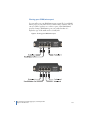
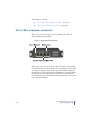
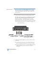
1
43!2 43!2 codes 43! codes 43! codes 43! -ARCH 43! 43! 43! codes 43! 43! codes 43 codes .ETWORK4!0S4EST!CCESS0ORTS Provides access to the data streams passing through a high-speed network device and a switch. Models available to monitor both copper and optical links. Customer Support Information Order toll-free in the U.S.: Call 877-877-BBOX (outside U.S. call 724-746-5500) FREE technical support 24 hours a day, 7 days a week: Call 724-746-5500 or fax s-AILINGADDRESS"LACK"OX#ORPORATION0ARK$RIVE,AWRENCE 0!s7EBSITEWWWBLACKBOXCOMs%MAILINFO BLACKBOXCOM FEDERAL COMMUNICATIONS COMMISSION and INDUSTRY CANADA RADIO FREQUENCY INTERFERENCE STATEMENTS This equipment generates, uses, and can radiate radio-frequency energy, and if not installed and used properly, that is, in strict accordance with the manufacturer’s instructions, may cause interference to radio communication. It has been tested and found to comply with the limits for a Class A computing device in accordance with the specifications in Subpart B of Part 15 of FCC rules, which are designed to provide reasonable protection against such interference when the equipment is operated in a commercial environment. Operation of this equipment in a residential area is likely to cause interference, in which case the user at his own expense will be required to take whatever measures may be necessary to correct the interference. Changes or modifications not expressly approved by the party responsible for compliance could void the user’s authority to operate the equipment. This digital apparatus does not exceed the Class A limits for radio noise emission from digital apparatus set out in the Radio Interference Regulation of Industry Canada. Le présent appareil numérique n’émet pas de bruits radioélectriques dépassant les limites applicables aux appareils numériques de la classe A prescrites dans le Règlement sur le brouillage radioélectrique publié par Industrie Canada. Normas Oficiales Mexicanas (NOM) Electrical Safety Statement INSTRUCCIONES DE SEGURIDAD 1 Todas las instrucciones de seguridad y operación deberán ser leídas antes de que el aparato eléctrico sea operado. 2 Las instrucciones de seguridad y operación deberán ser guardadas para referencia futura. 3 Todas las advertencias en el aparato eléctrico y en sus instrucciones de operación deben ser respetadas. 4 Todas las instrucciones de operación y uso deben ser seguidas. 5 El aparato eléctrico no deberá ser usado cerca del agua-por ejemplo, cerca de la tina de baño, lavabo, sótano mojado o cerca de una alberca, etc.. 6 El aparato eléctrico debe ser usado únicamente con carritos o pedestales que sean recomendados por el fabricante. 3 7 El aparato eléctrico debe ser montado a la pared o al techo sólo como sea recomendado por el fabricante 8 Servicio-El usuario no debe intentar dar servicio al equipo eléctrico más allá a lo descrito en las instrucciones de operación. Todo otro servicio deberá ser referido a personal de servicio calificado. 9 El aparato eléctrico debe ser situado de tal manera que su posición no interfiera su uso. La colocación del aparato eléctrico sobre una cama, sofá, alfombra o superficie similar puede bloquea la ventilación, no se debe colocar en libreros o gabinetes que impidan el flujo de aire por los orificios de ventilación. 10 El equipo eléctrico deber ser situado fuera del alcance de fuentes de calor como radiadores, registros de calor, estufas u otros aparatos (incluyendo amplificadores) que producen calor. 11 El aparato eléctrico deberá ser connectado a una fuente de poder sólo del tipo descrito en el instructivo de operación, o como se indique en el aparato. 12 Precaución debe ser tomada de tal manera que la tierra fisica y la polarización del equipo no sea eliminada. 13 Los cables de la fuente de poder deben ser guiados de tal manera que no sean pisados ni pellizcados por objetos colocados sobre o contra ellos, poniendo particular atención a los contactos y receptáculos donde salen del aparato. 14 El equipo eléctrico debe ser limpiado únicamente de acuerdo a las recomendaciones del fabricante. 15 En caso de existir, una antena externa deberá ser localizada lejos de las lineas de energia. 16 El cable de corriente deberá ser desconectado del cuando el equipo no sea usado por un largo periodo de tiempo. 17 Cuidado debe ser tomado de tal manera que objectos liquidos no sean derramados sobre la cubierta u orificios de ventilación. 18 Servicio por personal calificado deberá ser provisto cuando: A El cable de poder o el contacto ha sido dañado; u B Objectos han caído o líquido ha sido derramado dentro del aparato; o C El aparato ha sido expuesto a la lluvia; o D El aparato parece no operar normalmente o muestra un cambio en su desempeño; o E El aparato ha sido tirado o su cubierta ha sido dañada. Contents Chapter 1: TAPs Overview Security, convenience, and dependability . . . . . . . . . . . . . . . . . . . . . . . . . . . . . . . . . . . . . . . . . . . . . . . . . . 8 Deciding whether to use a TAP or a SPAN/mirror port . . . . . . . . . . . . . . . . . . . . . . . . . . . . . . . . . . . . . . . 8 Choosing between a SPAN, Aggregator, or full-duplex TAP. . . . . . . . . . . . . . . . . . . . . . . . . . . . . . . . . 10 When to use a SPAN/mirror port . . . . . . . . . . . . . . . . . . . . . . . . . . . . . . . . . . . . . . . . . . . . . . . . . . . . . . 12 When to use an Aggregator TAP . . . . . . . . . . . . . . . . . . . . . . . . . . . . . . . . . . . . . . . . . . . . . . . . . . . . . . 15 When to use a full-duplex TAP . . . . . . . . . . . . . . . . . . . . . . . . . . . . . . . . . . . . . . . . . . . . . . . . . . . . . . . . 17 Chapter 2: Copper TAPs Major features . . . . . . . . . . . . . . . . . . . . . . . . . . . . . . . . . . . . . . . . . . . . . . . . . . . . . . . . . . . . . . . . . . . . . . . . . . . . Standard and optional parts. . . . . . . . . . . . . . . . . . . . . . . . . . . . . . . . . . . . . . . . . . . . . . . . . . . . . . . . . . . . . . . Installing the Copper TAP . . . . . . . . . . . . . . . . . . . . . . . . . . . . . . . . . . . . . . . . . . . . . . . . . . . . . . . . . . . . . . . . . Ports, LEDs, and power connectors . . . . . . . . . . . . . . . . . . . . . . . . . . . . . . . . . . . . . . . . . . . . . . . . . . . . . . . . Interpreting the Link and Speed LEDs . . . . . . . . . . . . . . . . . . . . . . . . . . . . . . . . . . . . . . . . . . . . . . . . . . . . . 10/100 TAP . . . . . . . . . . . . . . . . . . . . . . . . . . . . . . . . . . . . . . . . . . . . . . . . . . . . . . . . . . . . . . . . . . . . . . . . . . 10/100/1000 TAP . . . . . . . . . . . . . . . . . . . . . . . . . . . . . . . . . . . . . . . . . . . . . . . . . . . . . . . . . . . . . . . . . . . . Technical specifications . . . . . . . . . . . . . . . . . . . . . . . . . . . . . . . . . . . . . . . . . . . . . . . . . . . . . . . . . . . . . . . . . . . 19 19 20 22 23 23 24 26 Chapter 3: Optical TAPs Major features . . . . . . . . . . . . . . . . . . . . . . . . . . . . . . . . . . . . . . . . . . . . . . . . . . . . . . . . . . . . . . . . . . . . . . . . . . . . Standard and optional parts. . . . . . . . . . . . . . . . . . . . . . . . . . . . . . . . . . . . . . . . . . . . . . . . . . . . . . . . . . . . . . . Installing the Optical TAP . . . . . . . . . . . . . . . . . . . . . . . . . . . . . . . . . . . . . . . . . . . . . . . . . . . . . . . . . . . . . . . . . Attenuation . . . . . . . . . . . . . . . . . . . . . . . . . . . . . . . . . . . . . . . . . . . . . . . . . . . . . . . . . . . . . . . . . . . . . . . . . . . . . . Attenuation and TAPs . . . . . . . . . . . . . . . . . . . . . . . . . . . . . . . . . . . . . . . . . . . . . . . . . . . . . . . . . . . . . . . . Determining the best split ratio for you . . . . . . . . . . . . . . . . . . . . . . . . . . . . . . . . . . . . . . . . . . . . . . . Attenuation and optical cables . . . . . . . . . . . . . . . . . . . . . . . . . . . . . . . . . . . . . . . . . . . . . . . . . . . . . . . Managing attenuation . . . . . . . . . . . . . . . . . . . . . . . . . . . . . . . . . . . . . . . . . . . . . . . . . . . . . . . . . . . . . . . Technical specifications . . . . . . . . . . . . . . . . . . . . . . . . . . . . . . . . . . . . . . . . . . . . . . . . . . . . . . . . . . . . . . . . . . . 28 28 29 31 31 32 38 39 40 Chapter 4: Aggregator TAPs Major features . . . . . . . . . . . . . . . . . . . . . . . . . . . . . . . . . . . . . . . . . . . . . . . . . . . . . . . . . . . . . . . . . . . . . . . . . . . . Standard and optional parts. . . . . . . . . . . . . . . . . . . . . . . . . . . . . . . . . . . . . . . . . . . . . . . . . . . . . . . . . . . . . . . Choosing an Aggregator TAP buffer size. . . . . . . . . . . . . . . . . . . . . . . . . . . . . . . . . . . . . . . . . . . . . . . . . . . Installing the Copper Aggregator TAP . . . . . . . . . . . . . . . . . . . . . . . . . . . . . . . . . . . . . . . . . . . . . . . . . . . . . Ports, LEDs, and power connectors . . . . . . . . . . . . . . . . . . . . . . . . . . . . . . . . . . . . . . . . . . . . . . . . . . . . . . . . 42 43 43 45 47 5 rev. 1 Interpreting the Link and Speed LEDs. . . . . . . . . . . . . . . . . . . . . . . . . . . . . . . . . . . . . . . . . . . . . . . . . . . . . . 48 Connection sequence . . . . . . . . . . . . . . . . . . . . . . . . . . . . . . . . . . . . . . . . . . . . . . . . . . . . . . . . . . . . . . . . 48 Chapter 5: FAQ and Troubleshooting What happens if my TAP loses power? . . . . . . . . . . . . . . . . . . . . . . . . . . . . . . . . . . . . . . . . . . . . . . . . . . . . . 52 What latency does a TAP create?. . . . . . . . . . . . . . . . . . . . . . . . . . . . . . . . . . . . . . . . . . . . . . . . . . . . . . . . . . . 52 Are the analyzer ports “send only”? . . . . . . . . . . . . . . . . . . . . . . . . . . . . . . . . . . . . . . . . . . . . . . . . . . . . . . . . 52 Can I daisy chain an Aggregator TAP? . . . . . . . . . . . . . . . . . . . . . . . . . . . . . . . . . . . . . . . . . . . . . . . . . . . . . . 52 Can I “team” NICs in my analyzer?. . . . . . . . . . . . . . . . . . . . . . . . . . . . . . . . . . . . . . . . . . . . . . . . . . . . . . . . . . 53 How do I connect my failover devices?. . . . . . . . . . . . . . . . . . . . . . . . . . . . . . . . . . . . . . . . . . . . . . . . . . . . . 55 Not seeing traffic at the analyzer from the TAP . . . . . . . . . . . . . . . . . . . . . . . . . . . . . . . . . . . . . . . . . . . . . 56 Choosing crossover or straight-through cables. . . . . . . . . . . . . . . . . . . . . . . . . . . . . . . . . . . . . . . . . . . . . 57 I am seeing CRC errors on my network . . . . . . . . . . . . . . . . . . . . . . . . . . . . . . . . . . . . . . . . . . . . . . . . . . . . . 57 VLAN tags not visible at the analyzer. . . . . . . . . . . . . . . . . . . . . . . . . . . . . . . . . . . . . . . . . . . . . . . . . . . . . . . 58 Index . . . . . . . . . . . . . . . . . . . . . . . . . . . . . . . . . . . . . . . . . . . . . . . . . . . . . . . . . . . . . . . . . . . . . 59 6 rev. 1 Chapter 1 TAPs Overview 7 Chapter 1 TAPs Overview rev. 1 Thank you for purchasing the TAP: the most robust, secure, and convenient mechanism for network analyzers and similar devices to copy data streams from high-capacity network links. A network Test Access Port (TAP) provides access to the data streams passing through a high-speed, full-duplex network link (typically between a network device and a switch. The TAP copies both sides of a full-duplex link (copper or optical, depending on type of TAP), and sends the copied data streams to an analyzer, probe, intrusion detection system (IDS) or any other passive analysis device. There are different TAP models available to monitor both copper and optical links. Security, convenience, and dependability The security and convenience of a TAP makes it preferable to inline connections for network analysis and intrusion detection and prevention (IDS/IPS) applications. Because a TAP has no address on the network, the TAP and the analyzer connected to it cannot be the target of a hack or virus attack. TAPs are economical to install, allowing you to leave them permanently deployed. This allows you to connect and disconnect the analysis device as needed without breaking the full-duplex connection, much like plugging in an electrical device. A TAP is also preferable to using a switch’s SPAN/mirror port to copy the data stream. Unlike the SPAN/mirror port, a TAP will not filter any errors from the data stream. Also, because a SPAN/mirror port is a half-duplex link (that is, a send-only “simplex” data stream), it has the capacity to transmit only half of a fully-saturated link. Additionally, a TAP does not use any of the switch’s CPU resources. Deciding whether to use a TAP or a SPAN/mirror port A TAP is a passive splitting mechanism installed between a device of interest and the network. A TAP copies the incoming network traffic and splits it. It passes the network traffic to the network and sends a copy of that traffic (both send and receive) to a monitoring device in real time. A switch cannot pass physical layer errors (poorly formed packets, runts, CRCs) to the analyzer, but a TAP will. 8 Security, convenience, and dependability Chapter 1 TAPs Overview rev. 1 Most enterprise switches copy the activity of one or more ports through a Switch Port Analyzer (SPAN) port, also known as a mirror port. An analysis device can then be attached to the SPAN port to access network traffic. Use Figure 1 and Table 1 to determine whether to use a TAP or a SPAN/mirror port. Figure 1 TAP versus SPAN rev. 1 Deciding whether to use a TAP or a SPAN/mirror port 9 Chapter 1 TAPs Overview Table 1 Pros and Cons of TAPs and SPANs Pros Cons TAP SPAN/mirror port Eliminates the risk of dropped packets Low cost Monitoring device receives all packets, including physical errors Remotely configurable from any system connected to the switch Provides full visibility into full-duplex networks Able to copy intra-switch traffic Analysis device may need dual-receive capture interface if you are using a full-duplex TAP (does not apply to Aggregator TAPs) Cannot handle heavily utilized full-duplex links without dropping packets Additional cost with purchase of TAP hardware Filters out physical layer errors, hampering some types of analysis Cannot monitor intra-switch traffic Burden placed on a switch’s CPU to copy all data passing through ports Switch puts lower priority on SPAN port data than regular port-to-port data Can change the timing of frame interaction altering response times Bottom line A TAP is ideal when analysis requires seeing all the traffic, including physical-layer errors. A TAP is required if network utilization is moderate to heavy. An Aggregator TAP can be used as an effective compromise between a TAP and SPAN port, delivering some of the advantages of a TAP and none of the disadvantages of a SPAN port. A SPAN port performs well on low-utilized networks or when analysis is not affected by dropped packets. Choosing between a SPAN, Aggregator, or full-duplex TAP There are numerous ways to access full-duplex traffic on a network for analysis: SPAN/mirror ports, Aggregator TAPs, or full-duplex TAPs are the three most common. Which you use depends on the saturation level of the link (up to 200% of link speed when both sides are combined) you want to monitor and the level of visibility you require. Each approach has advantages and disadvantages. SPANs and Aggregator TAPs are designed to work with a standard (and usually less expensive) network card on the analysis device, but their limitations make them less than ideal for situations where it is necessary to guarantee the visibility of every packet on the wire. A full-duplex TAP is the ideal solution for monitoring full-duplex networks utilized at more than 50 percent (100% when both sides are 10 Choosing between a SPAN, Aggregator, or full-duplex TAP Chapter 1 TAPs Overview rev. 1 combined), but its design requires that the analyzer be a specialized device with a dual-receive capture interface that is capable of capturing the TAP’s output, providing accurate timing, and recombining the data for analysis. Table 2 list the advantages and disadvantages of three common methods of accessing traffic from full-duplex networks for analysis, monitoring, or forensics: Table 2 Span vs Aggregator vs Full-duplex TAPs Aggregator SPAN/Mirror Full-Duplex 2 Uses single-receive capture card Uses internal buffer to mitigate traffic spikes Suitable for networks with light to moderate traffic with occasional spikes Passes OSI Layer 1 & 2 errors Not Addressable (cannot be hacked) Requires power May drop packets 1 Requires dual-receive capture card Ideal for heavy traffic/critical networks Suitable for networks with light to moderate traffic Remotely configurable 1. The optical TAPs do not require power, but the copper TAPs do. 2. Although an Aggregator TAP has an internal buffer that mitigates spikes in traffic, when the buffer itself is full, the new packets are dropped until the output of the buffer can catch up. Whether you are monitoring a network for security threats or capturing and decoding packets while troubleshooting, you need a reliable way to see the network traffic. The appropriate TAP for capturing full-duplex data for analysis depends on the rates of traffic you must monitor, and what level of visibility you require. Attaching a monitoring or analysis device to a switch’s analyzer port (SPAN/mirror port) to monitor a full-duplex link. Because a SPAN/mirror port is a send-only simplex stream of data there is a potential bottleneck when trying to mirror both sides of a full-duplex link to the analyzer’s single receive rev. 1 Choosing between a SPAN, Aggregator, or full-duplex TAP 11 Chapter 1 TAPs Overview channel. For more details, see “When to use a SPAN/mirror port” on page 12. Attaching a monitoring or analysis device to an Aggregator TAP inserted into a full-duplex link. As with a SPAN, the Aggregator TAP copies both sides of a full-duplex link to the analyzer’s single receive channel. It uses buffering which makes it somewhat better able to keep up with higher traffic levels than a SPAN. For more details, see “When to use an Aggregator TAP” on page 15 and “Choosing an Aggregator TAP buffer size” on page 43. Attaching a dual-receive monitoring or analysis device to a full-duplex TAP inserted into a full-duplex link. Dual-receive means that the network card on the analysis device has two receive channels rather than the transmit and receive channels associated with a standard full-duplex link. For more details, see “When to use a full-duplex TAP” on page 17. When to use a SPAN/mirror port The advantage to using a SPAN/mirror port is its cost, as a SPAN/ mirror port is included for free with virtually every managed switch. A SPAN/mirror port is also remotely configurable, allowing you to change which ports are mirrored from the switch management console. Limitations of a SPAN/mirror port stem from the aggregation necessary to merge full-duplex network traffic into a single receive channel. For examples, when traffic levels on the network exceed the output capability of the SPAN/mirror port, the switch is forced to drop packets. Another reason that a SPAN/mirror port may not be the right choice is because Layer 1 and 2 errors are not mirrored and therefore never reach the analyzer. When performing network troubleshooting, seeing these errors can be important. When monitoring with a SPAN/mirror port on a switch, the switch does three things: Copies both the send and receive data channels Reconstructs an integrated data stream from the two channels 12 Choosing between a SPAN, Aggregator, or full-duplex TAP Chapter 1 TAPs Overview rev. 1 Routes the integrated signal to the send channel of the SPAN/ mirror port Each of these activities burdens the switch’s internal processor. These demands on the switch’s CPU have implications for both your monitoring equipment and general network performance. Using a SPAN/mirror port to capture network traffic for analysis presents the following risks: As total bandwidth usage for both channels exceeds the capacity of the outbound link to the analyzer, the excess traffic is dropped from the analyzer stream. There simply is not enough bandwidth to transmit both sides of the fullduplex traffic across a single standard interface. The switch’s CPU must act as both a network switch and a packet-copier. The switch’s CPU must also integrate the two data streams (send and receive) together correctly. Both packet copy/re-direction and channel integration is affected by switch load. This means the SPAN/mirror port may not deliver accurate captures when the switch are under heavy load. Monitoring a 10/100 network through a gigabit SPAN/ mirror port and analyzer does not alleviate these concerns. Also, there is no notification when the SPAN/mirror port is dropping packets or delivering inaccurate time stamps. A SPAN/mirror port can deliver satisfactory results when used to monitor lightly used, non-critical networks. If network utilization exceeds the capacity of the outbound (analyzer) link, packet loss results—which invalidates many types of analysis, and makes monitoring for certain kinds of network activity impractical. For example, you might miss a virus signature because packets are being dropped. When analyzing a transaction or connection problem, the analyzer may detect problems where none exist because expected packets are being dropped by the SPAN/mirror port. Hardware and media errors will also be impossible to troubleshoot through a SPAN/ mirror port, as these errors are not mirrored to the analyzer. rev. 1 Choosing between a SPAN, Aggregator, or full-duplex TAP 13 Chapter 1 TAPs Overview Cloning your SPAN/mirror port You can still access your SPAN/mirror port even if all of your SPAN/ mirror ports on your switch are used. This is fairly common, and you can use a TAP to produce two or three copies of the SPAN/mirror port. By cloning a SPAN/mirror port you get the benefits of a duplicate copy of the traffic and no security risk. Figure 2 Cloning your SPAN/mirror port 14 Choosing between a SPAN, Aggregator, or full-duplex TAP Chapter 1 TAPs Overview rev. 1 Joining SPAN/mirror ports If you have a primary switch and a failover switch, you can connect both of them to an Aggregator TAP. Connect one of them to Link A and the other to Link B. It does not matter whether the primary switch is connected to Link A or Link B, and you do not need to know which one is “live.” The Aggregator TAP joins the active and inactive SPAN/mirror port session together and sends the result to the analyzer. Regardless which switch is primary the Aggregator TAP sends the SPAN/mirror port data from that switch to the analyzers. Figure 3 Joining SPAN/mirror ports When to use an Aggregator TAP An Aggregator TAP makes a good compromise between the SPAN/ mirror port and full-duplex TAP options. It costs more than a fullduplex TAP due to the added complexity and memory requirements of its built-in buffer. But it does not require a specialized (and potentially more expensive) analyzer with a dual-receive capture interface. Like a full-duplex TAP, it is independent of the network, making it immune to security threats. An Aggregator TAP includes an internal buffer to mitigate the bandwidth problem associated with converging both sides of the fullduplex traffic from the network into one side of the full-duplex link to the analyzer. The buffer is able to cache some spikes in network utilization, but an Aggregator TAP drops packets when the bursts of activity exceed its buffer capacity. rev. 1 Choosing between a SPAN, Aggregator, or full-duplex TAP 15 Chapter 1 TAPs Overview NOTE: TAP BUFFER The role of the buffer is to absorb traffic spikes of over 50% full-duplex bandwidth saturation (100% with both sides combined), because the analyzer’s single-receive interface cannot receive the traffic fast enough to keep up at line rate. For more details about the Aggregator TAP’s buffer, see “Choosing an Aggregator TAP buffer size” on page 43. An Aggregator TAP is ideally suited to work with an analysis device with a standard, single-receive capture interface or NIC. This means that a laptop or a standard system can be deployed as an analyzer rather than the more expensive specialized analyzers or appliances that are designed to accept full duplex traffic through a dual-receive capture interface. Just like a SPAN/mirror port, an Aggregator TAP is ideal for a lightly used network that occasionally has utilization peaks above the capture capacity of the analyzer. Unlike a SPAN/mirror port, the Aggregator TAP will forward Layer 1 and 2 errors to the analysis device. Another advantage the Aggregator TAP has over a SPAN/mirror port session is its internal memory buffer. The memory buffer provides limited protection against packet loss, and if the network utilization does not regularly exceed the capacity of the analyzer’s capture card, an Aggregator TAP may be the right choice. The appropriate solution for capturing full-duplex data for analysis depends on the rates of traffic you must monitor, and what level of visibility you require. When monitoring a lightly-used network, using a SPAN/mirror port or Aggregator TAP to supply an analysis device with a standard NIC (i.e., single-receive) interface can be an economical choice. The Aggregator TAP can provide protection against packet loss, but if usage spikes exceed its buffer capacity before the link to the analyzer can catch up, the Aggregator TAP drops packets. To monitor a critical, heavily utilized full-duplex link, a full-duplex TAP is the only alternative. Monitoring a full-duplex connection using a full-duplex TAP and an analyzer with a dual-receive capture interface guarantees complete, full-duplex capture for monitoring, analysis, and intrusion detection regardless of bandwidth saturation. See “Aggregator TAPs” on page 41 for full details about the TAPs. 16 Choosing between a SPAN, Aggregator, or full-duplex TAP Chapter 1 TAPs Overview rev. 1 When to use a full-duplex TAP A full-duplex TAP is the only method of the three options that guarantees that all of the network traffic, including Layer 1 and 2 error information, makes it to the analysis device. It is more complex and potentially expensive to implement, but where there is high network utilization and it is important to guarantee the capture of “everything on the wire” along with errors from all network layers, a full-duplex TAP is the only choice. If the analysis requires a high level of data stream fidelity (for instance, looking for jitter in video or VoIP), only a full duplex TAP forwards the original data timing to the analyzer. A full-duplex TAP is a passive mechanism that is installed between two full-duplex network devices. An optical TAP is non-electronic (no power) and optically splits the full-duplex signal into two full-duplex signals. One signal maintains the network link, while the other is passed to an analyzer equipped with a dual-receive capture card. A copper TAP performs the same function, but uses electronic circuitry to duplicate the signals. Because a full-duplex TAP copies both the send and receive channels from a full-duplex link to the analyzer (where the data is integrated), the analyzer can monitor a full-duplex network at line rate—assuming the capture card in the analyzer is capable of keeping up. A full-duplex TAP must be coupled with a probe or monitoring device capable of receiving both channels of a full-duplex signal and recombining the two channels into a single data stream for analysis. Although this can be the most expensive solution, it is also the only solution that guarantees complete accuracy even when the network is highly saturated. All TAPs from Black Box, except the Aggregator TAPs, are fullduplex. See “Copper TAPs” on page 18 and “Optical TAPs” on page 27 for more details about each type of full-duplex TAP. rev. 1 Choosing between a SPAN, Aggregator, or full-duplex TAP 17 Chapter 1 TAPs Overview Chapter 2 Copper TAPs 18 rev. 1 Chapter 2 Copper TAPs Major features The major features of the Black Box full-duplex Copper TAPs are: Passive access at 10/100 or 1000 Mbps without packet tampering or introducing a single point of failure No packet loss if the TAP loses power Automatic link failover for devices that have an alternate path Allows you to connect and disconnect the analysis device as needed without taking the network down Optional redundant power ensures maximum monitoring uptime All traffic (including errors) is passed from all OSI layers for troubleshooting Enhanced security because the TAP does not require or use an IP address, which makes it, and the analyzer connected to it, impervious to viruses and other attacks LEDs show power and link status Optional 19-inch rack frames hold up to three TAPs Front-mounted connectors make installation simple Fully IEEE 802.3 compliant Fully RoHS compliant Standard and optional parts Carefully unpack the TAP and check for damaged or missing parts. The TAP ships with the following items: Copper 10/100 or 10/100/1000 TAP Voltage auto-sensing universal power supply and A/C power cord Manual Your kit may also contain: rev. 1 Major features 19 Chapter 2 Copper TAPs Patch cable(s) Redundant power supply Rack or bay mount If any part is missing or damaged, contact Black Box Support immediately. Installing the Copper TAP After reviewing the information in “Deciding whether to use a TAP or a SPAN/mirror port” on page 8 and “Choosing between a SPAN, Aggregator, or full-duplex TAP” on page 10, you decided a Copper TAP was the right one for you. Use the information in this section to install your TAP. To install the Copper TAP, you must: Decide where to place the TAP, and physically mount it, if desired. This will be in a PC drive bay, rack mount bracket, or wherever it is most convenient. For efficient heat dissipation, keep the TAP horizontal. Use standard Ethernet cables with RJ-45 connectors to complete the pass-through connection between the device of interest and the network. The 10/100 TAP must use straightthrough cables. It cannot use crossover cables. The 10/100/ 1000 TAP may use crossover cables. See “Choosing crossover or straight-through cables” on page 57. Connect the TAP to your analyzer or other monitoring device using standard Ethernet cables. The Copper TAP transmits the analyzer signals through a pair of 10/ 100 or 10/100/1000 BaseT RJ-45 ports. 20 Installing the Copper TAP Chapter 2 Copper TAPs rev. 1 NOTE: INSIDE THE TAP When traffic comes in to Link A, two copies are made in the TAP. One copy is sent out Link B to the switch and the other copy is sent out Analyzer A to the analysis device. A similar thing happens with traffic that comes in Link B. Two copies are made. One copy is sent out Link A and the other copy is sent out Analyzer B. Figure 4 Connecting the TAP to the network device, switch, and analyzer CAUTION rev. 1 Before you temporarily break the link between the device of interest and the network, you may want to shut down access to that device and notify users of the down time. 1 Ensure that power is connected to the TAP. You can supply power to one or both power supply sockets on the back panel of each TAP. Connecting both sockets to different external power sources provides fail-safe power redundancy for the Analyzer side. The network pass-through (Link side) remains unaffected even if power to the TAP is interrupted. If you do lose power, you will temporarily lose connectivity while the devices renegotiate their connection. The analyzer side will be down until power is reestablished. 2 Connect your device (typically a switch) to Link B. You want to connect Link B first because it negotiates its network speed first Installing the Copper TAP 21 Chapter 2 Copper TAPs and Link A then must use the same speed as Link B. If your link is under test as part of a failover or redundancy arrangement, then connect the failover device to Link B. See “How do I connect my failover devices?” on page 55. NOTE: TAP NOT CONNECTING 3 Connect your network device (or primary device in a failover arrangement) to Link A. 4 Connect the Analyzer ports on the TAP to the dual-receive interface on the monitoring device. If you are attempting to connect to a device with a 1000 Mb NIC and your 10/100 TAP is not linking, this is likely due to the auto-negotiation feature. To allow the TAP to connect, you must force the NIC in your device to 100 Mb full duplex. Ports, LEDs, and power connectors This section provides a brief overview of installing the TAP and understanding the status LEDs. The front panel will differ slightly depending on which TAP model you have purchased. The 10/100 (not shown) does not have the 1000 Mb speed indicator light. Figure 5 10/100 and 10/100/1000 Copper TAP Both power connectors are located on the back panel, along with the model information and serial number. You can supply power to either 22 Ports, LEDs, and power connectors Chapter 2 Copper TAPs rev. 1 or both power supply sockets. Connecting both sockets to different external power sources (using Network Instrument’s optional adapter kit TC2P-K) provides fail-safe power redundancy for the Analyzer side. The network pass-through link remains unaffected even if power to the TAP is interrupted. For a detailed description of what happens, read the information in “10/100/1000 TAP” on page 24. Figure 6 Back panel showing power connectors and serial number Interpreting the Link and Speed LEDs This section describes the LEDs and what they mean when they flash and flicker on the 10/100 and 10/100/1000 TAPs. 10/100 TAP The 10/100 TAP is passive, which means no packets are lost or delayed if power is lost. The 10/100 TAP supports Power over Ethernet (PoE). When powered up, the TAP performs a sequence of steps to determine whether its link ports are connected to any devices, and what speeds and other capabilities those devices have. The blinking pattern of the LEDs indicate which step of the connection process the TAP is performing. The duration of each state depends on the type of equipment attached to each port of the TAP. Here are the connection steps, listed in the order they occur: rev. 1 1 Capabilities search. Both the 10 and 100 LEDs are solidly lit until a connection speed is determined. 2 Connecting. After a connection speed is determined, then that speed’s connection LED remains lit while the other goes dark. Interpreting the Link and Speed LEDs 23 Chapter 2 Copper TAPs 3 Connected. The Speed LED is on and the Link LED shows activity. The Link LEDs flicker faster when there is more traffic on the Link and slower when there is less traffic. The Analyzer LEDs follow the Link LEDs. Because the TAP is passive, all activity on the Link port is automatically and passively copied to the Analyzer port and therefore the Analyzer port LED blinks at the same speed as the Link port — even if an analyzer is not connected. 10/100/1000 TAP With a 10/100/1000 Mb Copper TAP, the TAP must be an active participant in the negotiated connections between the network devices attached to it. This is true if the TAP is operating at 10, 100, or 1000 Mb. Power failure to the TAP results in the following: If you are using a redundant power supply (Part # TC2P-K) or the TAP is attached to an uninterrupted power supply, it provides power with no loss of network connection. If you are not using a redundant power supply or UPS or power to both power supplies is lost, then: The Analyzer ports stop working and the analysis device(s) connected to the TAP will go “dark.” The TAP continues to pass data between the network devices connected to it (firewall/router/switch to server/ switch). In this sense the TAP is passive. The network devices connected to the TAP on the Link ports must renegotiate a connection with each other because the TAP has dropped out. This may take a few seconds. When powered up, the TAP performs a sequence of steps to determine whether its link ports are connected to any devices, and what speeds and other capabilities those devices have. The blinking pattern of the LEDs indicate which step of the connection process the TAP is performing. The duration of each state depends on the type of equipment attached to each port of the TAP. Here are the connection steps, listed in the order they occur: 1 Capabilities search. Both link ports/connections on the TAP are attempting to attach to their respective devices and determine a 24 Interpreting the Link and Speed LEDs Chapter 2 Copper TAPs rev. 1 common speed and other capabilities. The LED pattern is that the Speed LEDs flash and the Link LEDs flicker. 2 Connecting. The link parameters are attempting to connect using the parameters determined during the Capabilities search. The LED pattern is that the TAP shows the connection speed while the Link LEDs continue to flicker. 3 Connected. Both link ports/connections are connected to the link partners at a common speed. The Speed LED shows connection speed. The Link LEDs light steadily (idle) or flicker depending on whether there is any traffic present. If a Link LED is unlit, there is no functioning device connected to that port. See “How do I connect my failover devices?” on page 55 for details about what happens when a primary device fails. Error conditions are shown by the Speed LEDs for approximately 10 seconds, after which the TAP resets itself (goes back to the Search connection step). Table 3 Errors LED Pattern Error Condition The Speed LED lights repeat the following sequence: 10 → 100 → 1000. No Common Speed. There is no common speed capability between the devices attached to Link A and Link B. The 10 LED flashes. The other Speed LEDs are on and do not flash. Timed Out. The TAP software has timed out waiting for some event. The expected speed’s LED is on, while the actual speed’s LED flashes. Wrong Speed. One of the links has connected at the wrong speed. The 1000 LED flashes. The other Speed LEDs are on and do not flash. Logic Error. This error occurs when the link partner capabilities are ambiguous. rev. 1 Interpreting the Link and Speed LEDs 25 Chapter 2 Copper TAPs Technical specifications This section lists the dimensions, power requirements, supported media, and environmental requirements. For the regulatory compliance statements, see “FCC compliance statement” on page 24. Table 4 Technical specifications Power requirements AC Input 90V - 264V, 47-63Hz Operational Voltage 5V (+10%/-5%, < 100 mV ripple) Operational Current Typical: <= 1.8 amps; Max: <= 2.8 amps Power Dissipation Typical: 8 watt; Max: 14 watt Environmental requirements Temperature range 32o - 120o F/0o - 55o C (Operating); 32º-167º F/0o - 75o C (Storage) Humidity 35-85% (non-condensing) Supported media Link ports 10/100: Straight-through RJ-45 cable 10/100/1000: Straight-through RJ-45 cable or crossover cable Analyzer ports 10/100: Straight-through RJ-45 cable 10/100/1000: Straight-through RJ-45 cable or crossover cable Dimensions Width 5.62 in/14.28 cm Height 1.15 in/2.93 cm Length 7.79 in/19.78 cm 26 Technical specifications Chapter 2 Copper TAPs rev. 1 Chapter 3 Optical TAPs 27 Chapter 3 Optical TAPs rev. 1 Major features The major features of the Black Box full-duplex Optical TAPs are: Passive access at 1 Gbps or 10 Gbps without packet tampering Allows you to connect and disconnect the analysis device as needed without taking the network down All traffic (including errors) is passed from all OSI layers for troubleshooting Enhanced security because the TAP does not require or use an IP address, which makes it, and the analyzer connected to it, impervious to viruses and other attacks Optional 19-inch rack frames hold up to three TAPs Front-mounted connectors make installation simple Fully RoHS compliant Standard and optional parts Carefully unpack the TAP and check for damaged or missing parts. The TAP ships with the following items: TAP Manual Your kit may also contain: Patch cable(s) Analyzer cable(s) Rack or bay mount If any part is missing or damaged, contact Black Box Support immediately. 28 Major features Chapter 3 Optical TAPs rev. 1 Installing the Optical TAP After reviewing the information in “Deciding whether to use a TAP or a SPAN/mirror port” on page 8 and “Choosing between a SPAN, Aggregator, or full-duplex TAP” on page 10, you decided an Optical TAP was the right one for you. Use the information in this section to install your TAP. To install the TAP, you must: Decide where to place the TAP and physically mount it, if desired. Depending on the form factor purchased, this will be in a PC drive bay, rack mount bracket, or wherever it is most convenient. Use the TAP cables you purchased (or your own optical patch cables) to complete the pass-through connection between the device of interest and the network. Connect the TAP to your analyzer or other monitoring device. Be certain to connect to the receive ports on the two NICs in your analyzer. These steps are described in more detail in the sections that follow. An Optical TAP splits the full-duplex signals, allowing the monitoring device access to a copy of the data stream while maintaining uninterruptable data flow through the monitored link. Optical TAPs require no external power, and are available in various split ratios to match the optical signal strength requirements of the network connections and of the monitoring equipment. rev. 1 Installing the Optical TAP 29 Chapter 3 Optical TAPs Figure 7 Cabling the Optical TAP To cable the Optical TAP, follow the steps outlined below. The example and diagram show how to monitor the link between a server and switch. CAUTION 30 Installing the Optical TAP Chapter 3 Optical TAPs Before you temporarily break the link between the device of interest and the network, you may want to shut down access to that device and notify users of the down time. 1 Disconnect the optical cable from the switch and connect it to the TAP’s Link B port. 2 Use another full-duplex optical cable to connect the server, router, firewall, or switch to the TAP’s Link A port, thus completing the pass-through link. 3 Use a Y-cable (i.e., a splitter cable) to connect the TAP’s Analyzer port to the receive sockets on your analyzer’s capture interface. Be certain to connect the cable to the receive ports on the two NICs in your analyzer. 4 Confirm that auto-negotiation on the receive NIC in your analyzer is disabled. See the documentation for your NIC or rev. 1 analyzer for details. If auto-negotiation is not disabled, the analyzer will not be able to receive the stream from the TAP until it is. As an alternative, you can split your own duplex cable (or use two simplex cables) to connect each side of the Analyzer ports on the TAP to the receive ports on each of the NICs in the analyzer. Attenuation Network administrators who manage optical links have the added challenge of dealing with signal attenuation—the rate at which light dissipates over a network. Attenuation is caused by a number of factors and can affect both network performance and the ability to analyze the network. Excessive signal attenuation can cause link failure. Understanding signal levels, selecting the right split ratio on TAPs, and carefully managing the location of repeaters can prevent problems. This section defines attenuation, explains how it is affected by fiber and other optical elements on a network, and how it can be efficiently managed. Attenuation is the reduction of signal strength during transmission caused by the absorption of light from the materials through which it travels. Greater signal loss equals higher attenuation. A signal can lose intensity or experience increased attenuation with each surface or medium it traverses. Many factors contribute to the attenuation rate of signals including devices such as TAPs and transmission through optical cables. Optical signal strength is measured in decibels (dB) and is based on a logarithmic scale. If a signal attenuates too much, the destination device cannot identify it, or worse, the signal may not even reach the destination. This is why some optical links depend on repeaters, which amplify the signal. Attenuation and TAPs TAPs are used to provide access to the data streams passing through a high-speed, full-duplex network link. TAPs deliver a complete copy of data to a monitoring device for accurate analysis. An Optical TAP optically splits the light power of the full-duplex signal into two rev. 1 Attenuation 31 Chapter 3 Optical TAPs copies. One part of the split signal is sent to the other device on the network, while the other is simultaneously passed to the analysis or monitoring appliance. As with all devices inserted into an optical link, one side effect of TAP usage is signal attenuation. A TAP attenuates the signal for two reasons: A portion of the signal strength is “siphoned off” and sent to the analyzer. How much of the signal strength is redirected for analysis depends on the split ratio of the TAP. The connections and internal TAP cables and connectors absorb and refract a small portion of the signal. An Optical TAP contributes to signal attenuation, but typically not enough to make a significant difference on the network. An optical split ratio must be designated on each TAP. In most cases, a 50/50 split ratio is ideal, providing sufficient light to both the network and monitoring device. However, there may be special cases that require an alternative ratio in order to meet signal power needs. For example, if a TAP is cabled close to the analyzer NIC and the link under test requires a long cable run, you may want to provide more light power back to the network than to the monitoring device. If you do choose a ratio other than 50/50, keep in mind that the signal has to be strong enough for it to be interpreted at the analyzer. Determining the best split ratio for you Fiber optic data travels on light power. A fiber optic TAP makes a copy of the data for the analyzer by splitting the light power. To ensure that all of the devices receive enough light power to establish and maintain a connection, you must understand where light can be “lost” as it travels between the network devices connected to the TAP and from the TAP to the analyzer. After the send strength and receive sensitivities of the ports and cable distances are known, a “power loss budget” can be calculated. The power loss budget can be helpful in determining if there is enough signal strength left at the analyzer receive port for a desired split ratio. The primary factors that need to be collected to determine loss budget are the: 32 Attenuation Chapter 3 Optical TAPs rev. 1 Transmit power from the network devices Cable distance from the network device to the TAP Maximum insertion loss from the TAP (see Table 5) Cable distance from the TAP to the analyzer Analyzer port receive sensitivity Other less crucial items that may also affect you include: Number or quality of any connectors or patch panels in the path to and from the TAP Age of the fiber cables Amount of heat in the environment where the fiber runs Table 5 Maximum insertion losses Maximum Insertion Losses in Decibels Multimode 50 micrometer Multimode 62.5 micrometer Single-Mode 9 micrometer 1300nm 850nm 1300nm 850nm 1310-1550 50/50 3.5/3.5 4.7/4.7 4.5/4.5 5.5/5.5 3.6/3.6 60/40 3.0/5.0 3.8/5.7 3.7/5.6 4.7/6.6 2.8/4.8 70/30 Split Ratio1 2.3/6.3 3.0/7.0 2.9/7.0 3.9/8.0 2.0/6.1 2 1.7/8.3 2.4/9.0 2.3/9.0 3.2/10.0 1.3/8.0 2 80/20 1.2/12.0 1.9/12.5 1.8/12.8 2.7/13.5 0.8/12 Fiber Loss/km3 1 3 1 3 0.4/0.3 Connector Loss .5 .5 .5 .5 .2 90/10 1. The ratio is network/analyzer. So, a 70/30 connection has 70% of the light power for the network and 30% for the analyzer. 2. Not recommended because too little light power reaches the analyzer. 3. Fiber loss is per kilometer of fiber. In each split ratio, what you are dividing is the light power from the incoming network link. The larger percentage of the light power is used for the connection to the other network device and the smaller portion is the light power for the analyzer. As long as there is sufficient light power, all data is still sent to the analyzer regardless of the split ratio chosen. rev. 1 Attenuation 33 Chapter 3 Optical TAPs Determining your power loss budget is a several step process that requires you to know the send power and receive sensitivities of the devices connected to the TAP, and requires that you do some basic math. Use these equations to determine the light available in decibels at the analyzer. 1 Determine your power loss budget by subtracting the receive sensitivity of the device connected to Link B from the send power of the device connected to Link A. Get these values from the device manufacturers. The amount of loss that you can have through attenuation and connector loss must be less than this power loss budget. (Send Device Power) – (Receive Device Sensitivity) = Power Loss Budget These values will be negative numbers, so you will be subtracting a negative number from a negative number and its product will be a positive number. 2 Determine the loss caused by attenuation. See Table 5 for values to assist you. If your cables are less than one kilometer, convert your cable length for the equation. (Number of Connectors * Connector Loss) + (Fiber Length of Link A * Fiber Loss) + (Fiber Length of Link B * Fiber Loss) = Attenuation 3 Subtract the output from step 2 from step 1. Power Loss Budget - Attenuation = Actual Loss If the actual loss is less than the power loss budget, then your budget is feasible with your chosen split ratio; however, you must also calculate the power loss budget for the analyzer from Link A and from Link B. Only if both power loss budgets are feasible is the chosen split ratio usable. 4 Determine your maximum insertion loss by subtracting the receive sensitivity of the analyzer from the send power from the device connected to Link A. Get these values from the device manufacturers. This is the amount of loss that you can have through attenuation and connector loss. (Send Device Power) – (Analyzer Sensitivity) = Power Loss Budget 5 34 Attenuation Chapter 3 Optical TAPs Determine the loss caused by attenuation. See Table 5 for values to assist you. rev. 1 (Number of Connectors * Connector Loss) + (Fiber Length of Link A * Fiber Loss) + (Fiber Length of Analyzer * Fiber Loss) = Attenuation 6 Subtract the output from step 5 from step 4. Power Loss Budget - Attenuation = Actual Loss 7 Repeat step 4 through step 6 for Link B to the analyzer. For example, Figure 8 shows cable lengths to the TAP from the network devices and from the TAP to the analyzer. Using these cable lengths and some information from the device manufacturers, you can determine the power loss. Figure 8 Cable lengths to/from the TAP The equations here are examples of how to calculate a power loss budget with actual values. rev. 1 Attenuation 35 Chapter 3 Optical TAPs This shows the power loss budget for Link A to Link B. Link A ↔ Link B Send Device Power -9.000 Receive Device Sensitivity - Power Loss Budget 10.500 Number of Connectors Connector Loss -19.5 4.0 x 0.5 1 Connector Loss 2.0 Fiber Length Link A (8 meters) Fiber Loss Link A 0.008 x 3.0 2 Fiber Loss Link A total + Fiber Length Link B (40 meters) 0.024 0.04 x 3.0 Fiber Loss Link B Fiber Loss Link B total Attenuation 3 Power Loss Budget - Attenuation + 0.120 - 2.144 8.356 1. Multimode. 2. 850nm multimode. 3. Light power available for network. Any network split ratio smaller than this number is feasible so long as the analyzer side is also feasible. The budget for the network side is 8.356 dB. Any split ratio is valid because 8.356 dB is greater than any of the insertion losses from Table 5 on page 33. Before we can say that any split ratio will work though, we must also check the light power to the analyzer. 36 Attenuation Chapter 3 Optical TAPs rev. 1 This shows the power loss budget for Link A to the analyzer. Link A → Analyzer Send Device Power -9.000 Receive Device Sensitivity - Power Loss Budget 9.000 Number of Connectors Connector Loss -17.5 4.0 x 0.5 1 Connector Loss 2.0 Fiber Length Link A (8 meters) Fiber Loss Link A 0.008 x 3.0 2 Fiber Loss Link A total + Fiber Length to Analyzer (75 meters) 0.024 0.075 x 3.0 Fiber Loss Analyzer Fiber Loss Link B total Attenuation 3 Power Loss Budget - Attenuation + 0.225 - 2.249 6.751 1. Multimode. 2. 850nm multimode. 3. Light power available for the analyzer. Any split ratio smaller than this number is feasible so long as the network side is also feasible. The budget for the analyzer side is 6.751 dB. The network side allowed us to choose any split ratio, but the analyzer side presents some limitations. Our budget was 9.0 dB, which is greater than our 6.751 dB availability. Since we only have 6.751 dB available, the split ratios we can use are 50/50 and 60/40 after looking at Table 5 on page 33. All others do not provide enough light power to the analyzer. rev. 1 Attenuation 37 Chapter 3 Optical TAPs Use this page to create your own power loss budget from Link A to Link B if you are considering an Optical TAP with a split ratio other than 50/50. Then use it for your Link A or Link B to the analyzer, whichever link has the longer fiber length. Use Table 5 on page 33 to assist you. Network → Analyzer Send Device Power Receive Device Sensitivity - Power Loss Budget Number of Connectors x Connector Loss Connector Loss Fiber Length Link A (or Link B) x Fiber Loss Link A (or Link B) Fiber Loss Link A (or Link B) total + Fiber Length to Analyzer x Fiber Loss Analyzer Fiber Loss Analyzer total + - Attenuation 1 Power Loss Budget - Attenuation 1. Light power available for analyzer. Any split ratio smaller than this number is feasible. Attenuation and optical cables Optical cables also contribute to signal attenuation. As light travels through an optical cable, some of its energy gets dispersed and absorbed by the cable. The attenuation rate varies depending on the cable type used. Depending on your transmission technology, you may be required to use a specific cable type. Examples include single-mode (for LX or LR) and multimode (for SX or SR). Multimode cable has a larger core diameter than single-mode cable, resulting in greater light dispersion. Unless the cable run is extremely long, the signal attenuation for both cable types is minor contributor to the power loss budget. However, multimode cable does cause higher signal attenuation than single- 38 Attenuation Chapter 3 Optical TAPs rev. 1 mode cable. Check with the cable manufacturer to determine specific attenuation rates. Managing attenuation Managing signal attenuation is critical for running a network at optimal performance. A problem arises when a signal is attenuated so much that the destination cannot interpret the signal or the signal fails in route. Repeaters can help, but they can be costly and inconvenient to implement. In general, unless a signal must travel a long distance or is compromised by patch panels, there should not be a problem using the 50/50 split ratio. The most efficient and cost-conscious way to manage attenuation is to measure signal levels throughout the network and place repeaters only when and where they are needed. To determine if a light signal is at an acceptable level at any point on a network, it is helpful to use an optical power meter. Optical power meters measure signal power at a port, helping you determine whether a device is receiving a strong enough signal and thereby identifying if repeaters need to be placed. The meters are typically inexpensive and are offered from a number of vendors. rev. 1 Attenuation 39 Chapter 3 Optical TAPs Technical specifications This section lists the dimensions, power requirements, supported media, and environmental requirements. For the regulatory compliance statements, see “FCC compliance statement” on page 24. Table 6 Technical specifications Power requirements AC Input None Environmental requirements Temperature range -40° to +185° (F) / -40° to +85° (C) (operating) -52° to +185° (F) / -47° to +85° (C) (storage) Humidity 35-85% (non-condensing) Supported media Fiber Multimode or Single-Mode Connector LC Fiber diameter Multimode: 50 or 62.5/125 micrometers (μm) Single-Mode: 9/125 micrometers Wavelength ranges Multimode: 850 or 1300 nanometers Single-Mode: 1310 or 1550 nanometers Wavelength tolerance ranges 850/1300 (Dual-window) Multimode +/- 20 nanometers 1310 or 1550 (Dual-window) Single-mode +/- 40 nanometers Insertion losses See “Maximum insertion losses” on page 33 in Table 5 Dimensions Width 5.62 in/14.28 cm Height 1.15 in/2.93 cm Length 7.79 in/19.78 cm LC connector adds .476 in/1.213 cm 40 Technical specifications Chapter 3 Optical TAPs rev. 1 Chapter 4 Aggregator TAPs 41 Chapter 4 Aggregator TAPs rev. 1 Major features An Aggregator TAPs provides a full-duplex pass through link for the connection being monitored. The TAP integrates both sides of the full-duplex link and sends the copied data out simplex (send only) ports to two analyzers. The Aggregator TAPs also provide a buffer (256 MB, 512 MB, or 1 GB) to protect against the packet loss that could otherwise result from traffic spikes where more data enters the TAP from the network than can be sent to the analyzer. These are the Aggregator TAPs: Copper Aggregator TAP The major features of the Black Box TAPs are: No packet loss if the TAP loses power Automatic link failover for devices that have an alternate path 42 Major features Chapter 4 Aggregator TAPs Passive access at 10/100/1000 Mbps without packet tampering or introducing a single point of failure Allows you to connect and disconnect the analysis device as needed without taking the network down Optional redundant power ensures maximum monitoring uptime All traffic (including errors) is passed from all OSI layers for troubleshooting Enhanced security because the TAP does not require or use an IP address, which makes it, and the analyzer connected to it, impervious to viruses and other attacks LEDs show power and link status Optional 19-inch rack frames hold up to 3 TAPs Front-mounted connectors make installation simple Fully IEEE 802.3 compliant Fully RoHS compliant rev. 1 Standard and optional parts Carefully unpack the TAP and check for damaged or missing parts. The TAP ships with the following items: Aggregator TAP Voltage auto-sensing universal power supply and A/C power cord Manual Your kit may also contain: Patch cable(s) Analyzer cable(s) Redundant power supply Rack or bay mount If any part is missing or damaged, contact Black Box Support immediately. Choosing an Aggregator TAP buffer size With the understanding that an Aggregator TAP is designed for use on network links with low-to-moderate utilization, they do have their place. You should know what your network utilization is before you decide to use an Aggregator TAP. If your network utilization is too high, an Aggregator TAP may not be the correct solution for you. The internal buffer helps absorb traffic spikes of over 50% full-duplex bandwidth saturation (100% when both data streams are combined), because the analyzer’s single receive interface is limited to line rate, and the amount of data on the network under analysis can be two times the line rate. The data in the buffer is released when utilization drops to the point where the analyzer interface can move both the “live” data plus the data released from the buffer. Packet loss is unavoidable if the utilization spikes exceed the capacity of the buffer. Packet loss occurs only to the analyzer. No traffic loss occurs between Link A (typically a router, firewall, or server) and Link B (typically a switch). rev. 1 Standard and optional parts 43 Chapter 4 Aggregator TAPs To monitor links that are well over 50% utilization for minutes at a time, a full-duplex TAP may be a better choice. After the buffer is full, an Aggregator TAP will drop packets. Use Figure 9 to choose the best buffer size for your Aggregator TAP. The graph shows the buffer size and duration of traffic spikes that the buffer can absorb. NOTE: LINK SPEEDS The Link side and Analyzer side of the Aggregator TAP negotiate their connections independent of each other. This means that the Link/network side can be at a speed slower than or up to the same speed as the Analyzer side. It cannot be faster than the Analyzer side. This is true whether you use a copper or optical connection to the analyzer. For instance, if your Link/network side is at 10 Mb or 100 Mb and your analyzer connection is 1 Gb, the TAP sends data to the analyzer at 1 Gb, known as up-converting, and there is no chance of over-subscribing the buffer. If your Link/network side is 1 Gb, then your connection to the analyzer must also be 1 Gb. It cannot be 10 Mb or 100 Mb, because the analyzer cannot receive the traffic from the Link side fast enough. 44 Choosing an Aggregator TAP buffer size Chapter 4 Aggregator TAPs rev. 1 Figure 9 Bandwidth utilization that a buffer can absorb on a gigabit network Installing the Copper Aggregator TAP After reviewing the information in “Deciding whether to use a TAP or a SPAN/mirror port” on page 8 and “Choosing between a SPAN, Aggregator, or full-duplex TAP” on page 10, you decided an Copper Aggregator TAP was the right one for you. Use the information in this section to install your TAP. To install the Copper Aggregator TAP, you must: rev. 1 Decide where to place the TAP, and physically mount it, if desired. This will be in a PC drive bay, rack mount bracket, or wherever it is most convenient. For efficient heat dissipation, keep the TAP horizontal. Use standard Ethernet cables with RJ-45 connectors to complete the pass-through connection between the device of interest and the network. See “Choosing crossover or straightthrough cables” on page 57. Installing the Copper Aggregator TAP 45 Chapter 4 Aggregator TAPs Connect the TAP to your analyzer or other monitoring device using standard Ethernet cables. Figure 10 Connecting the TAP to the network device, switch, and analyzer CAUTION Before you temporarily break the link between the device of interest and the network, you may want to shut down access to that device and notify users of the down time. 1 Ensure that power is connected to the TAP. You can supply power to one or both power supply sockets on the back panel of each TAP. Connecting both sockets to different external power sources provides fail-safe power redundancy for the Analyzer side. The network pass-through (Link side) remains unaffected even if power to the TAP is interrupted. If you do lose power, you will temporarily lose connectivity while the devices renegotiate their connection. The Analyzer side will be down until power is reestablished. 2 Connect your device (typically a switch) to Link B. You want to connect Link B first because it negotiates its network speed first and Link A then must use the same speed as Link B. If your link is under test as part of a failover or redundancy arrangement, then connect the failover device to Link B. See “How do I connect my failover devices?” on page 55. 3 Connect your network device (or primary device in a failover arrangement) to Link A. 4 Connect the Analyzer ports on the TAP to the analyzer(s). 46 Installing the Copper Aggregator TAP Chapter 4 Aggregator TAPs rev. 1 Other things to consider: “Can I daisy chain an Aggregator TAP?” on page 52 “Can I “team” NICs in my analyzer?” on page 53 Ports, LEDs, and power connectors This section provides a brief overview of installing the TAP and understanding the status LEDs. Figure 11 Aggregator TAP front panel Both power connectors are located on the back panel, along with the model information and serial number. You can supply power to either or both power supply sockets. Connecting both sockets to different external power sources (using Network Instrument’s optional adapter kit TC2P-K) provides fail-safe power redundancy for the Analyzer side. The network pass-through link remains unaffected even if power to the TAP is interrupted. rev. 1 Ports, LEDs, and power connectors 47 Chapter 4 Aggregator TAPs Figure 12 Back panel showing power connectors and serial number Interpreting the Link and Speed LEDs When the TAP is powered up and correctly connected to functioning devices, the Speed LED indicators simply show the connection speed. The Link LED indicators are either lit steadily (idle) or flicker (data transfer) depending on whether there is any traffic present. Connection sequence When powered up, the TAP performs a sequence of steps to determine whether its link ports are connected to any devices, and what speeds and other capabilities those devices have. The blinking pattern of the LEDs indicate which step of the connection process the TAP is performing. The duration of each state depends on the type of equipment attached to each port of the TAP. Here are the connection steps, listed in the order they occur: 1 Capabilities search. Both link ports/connections on the TAP are attempting to attach to their respective devices and determine a common speed and other capabilities. The LED pattern is that the Speed LEDs flash and the Link LEDs flicker. 2 Connecting. The link parameters are attempting to connect using the parameters determined during the Capabilities search. The LED pattern is that the TAP shows the connection speed while the Link LEDs continue to flicker. 3 Connected. Both link ports/connections are connected to the link partners at a common speed. The Speed LED shows connection speed. The Link LEDs light steadily (idle) or flicker depending on 48 Interpreting the Link and Speed LEDs Chapter 4 Aggregator TAPs rev. 1 whether there is any traffic present. If a Link LED is unlit, there is no functioning device connected to that port. See “How do I connect my failover devices?” on page 55 for details about what happens when a primary device fails. Error conditions are shown by the Speed LEDs for approximately 10 seconds, after which the TAP resets itself (goes back to the Search connection step). Table 7 Errors LED Pattern Error Condition The Speed LED lights repeat the following sequence: 10 → 100 → 1000. No Common Speed. There is no common speed capability between the devices attached to Link A and Link B. The 10 LED flashes. The other Speed LEDs are on and do not flash. Timed Out. The TAP software has timed out waiting for some event. The expected speed’s LED is on, while the actual speed’s LED flashes. Wrong Speed. One of the links has connected at the wrong speed. The 1000 LED flashes. The other Speed LEDs are on and do not flash. Logic Error. This error occurs when the link partner capabilities are ambiguous. Technical specifications This section lists the dimensions, power requirements, supported media, and environmental requirements. For the regulatory compliance statements, see “FCC compliance statement” on page 24. Table 8 Technical specifications Power requirements AC Input 90V - 264V, 47-63Hz Operational Voltage 5V (+10%/-5%, < 100 mV ripple) Operational Current Typical: <= 1.8 amps; Max: <= 2.8 amps Power Dissipation Typical: 8 watt; Max: 14 watt Environmental requirements Temperature range -40° to +185° (F) / -40° to +85° (C) (operating) -52° to +185° (F) / -47° to +85° (C) (storage) Humidity 35-85% (non-condensing) Supported media rev. 1 Interpreting the Link and Speed LEDs 49 Chapter 4 Aggregator TAPs Table 8 Technical specifications (Continued) Link ports Copper: Straight-through RJ-45 cable or crossover cable Copper-to-Optical: Straight-through RJ-45 cable or crossover cable Optical-to-Copper: Fiber diameter: Multimode: 50 or 62.5/125 micrometers (μm) Single-mode: 9/125 micrometers Wavelength ranges Multimode: 850 or 1300 nanometers Single-mode: 1310 or 1550 nanometers Copper Analyzer ports Straight-through RJ-45 cable or crossover cable Buffer size 256 MB 512 MB 1 GB Dimensions Width 5.62 in/14.28 cm Height 1.15 in/2.93 cm Length 7.79 in/19.78 cm 50 Interpreting the Link and Speed LEDs Chapter 4 Aggregator TAPs rev. 1 Chapter 5 FAQ and Troubleshooting 51 Chapter 5 FAQ and Troubleshooting rev. 1 What happens if my TAP loses power? If your copper TAP loses power (optical TAPs do not require power), the TAP will not be able to send data to the analyzer. You will temporarily lose network connectivity, but it will be re-established as soon as the two devices connected to the Link ports can renegotiate a connection with each other. This could take a few seconds and is completely dependent on the network and the devices. What latency does a TAP create? A Black Box TAP’s latency is 200-250 nanoseconds. This is the time it takes to receive the packet, process and copy it, and send it out the other side (Link A to Link B). Optical TAPs are non-electronic and do not introduce any delay. Are the analyzer ports “send only”? Yes, the analyzer ports are send only. The full-duplex and Copper Aggregator TAPs are incapable of sending data from the Analyzer side of the TAP to the Link (or network) side of the TAP. The “A,” “B,” or “AB” ports on the Analyzer side of the TAP must be capable of both transmitting and receiving data to negotiate a connection with the analyzer and they do this through the physical interface. The physical interface is responsible for negotiating a bidirectional connection with the analyzer and unidirectionally sending data from the TAP to the analyzer. There is no physical connection between the receive port on the Analyzer side of the TAP and the TAP’s internal processor. Therefore, the TAP cannot transmit data from the analyzer back to the Link/ network side of the TAP. Can I daisy chain an Aggregator TAP? Yes, you can daisy chain TAPs, but it is not recommended because of the negotiation time and latency introduced by the TAP. Although the latency is very small, if the packets do not reach their destination fast enough and the receiving device has a low MTU (maximum 52 What happens if my TAP loses power? Chapter 5 FAQ and Troubleshooting rev. 1 transmission unit), the receiving device could restart the negotiation process. For more details, see “Not seeing traffic at the analyzer from the TAP” on page 56. If you are attempting to daisy chain Aggregator TAPs to more than two analyzers and you are certain your MTU on the receiving devices is high enough, contact Black Box Support for assistance. Can I “team” NICs in my analyzer? Yes, it is possible, with some caveats. Sometimes it is desirable to use two standard full-duplex NICs to capture full-duplex TAP output for analysis. Because a standard NIC port has only one receive channel, you must aggregate the receive channels from two ports to see both sides of the two-way connection being monitored. Intel’s Advanced Network Services allows you to team multiple connections at the driver level, presenting your analyzer with an aggregated view of send and receive channels. Because of the processing overhead and its affect on NIC performance, this method is not recommended for monitoring moderate to highly saturated links, such as those between switches. However, it can be an economical alternative when monitoring more lightly used connections, such as between a server and switch. In addition to the bandwidth limitations, connection teaming is also less accurate when timestamping packets, which can cause unexpected results when your analyzer attempts to display certain charts and statistics such as Connection Dynamics or VoIP jitter. You also will not be able to tell which side is DCE vs. DTE. In short, if you do not have a dual-receive analysis NIC, it is always better to analyze the SPAN or port mirror session through a standard NIC rather than using the connection teaming method described here. rev. 1 Can I “team” NICs in my analyzer? 53 Chapter 5 FAQ and Troubleshooting NOTE: REQUIREMENTS You need at least one IntelPro/1000 card that supports Advanced Network Services. If the card has two ports, they can be teamed, otherwise another NIC with an unused port must be present. 1 Connect the TAP to the analyzer using the appropriate cables. The TAP is cabled between the devices being monitored normally (i.e., it provides a pass-through circuit for the link under test). Instead of connecting to a single dual-receive port (as is the preferred deployment), connect the send lines to the transmit (TX) sides of the two ports you intend to aggregate. You can team ports on separate cards as long as one of them is an IntelPro card. Figure 13 NIC teaming 2 Configure the IntelPro/1000 Driver Software to Define Teamed Connections A Open Network Connections by right clicking My Network Places on the Windows Start menu and choosing Properties. B Right-click a Monitor Port from an IntelPro/1000 card (which one does not matter) and choose Properties. Click the Teaming tab. 54 Can I “team” NICs in my analyzer? Chapter 5 FAQ and Troubleshooting rev. 1 C Choose the “Team with other adapters” option and then click New Team... to start the New Team Wizard. The first dialog lets you name the Team (you may want to call it something like “Virtual Dual-receive”). D Click Next and add another adapter/port that supports teaming (for example the second port on a dual-port IntelPro card). E Click Next and choose Static Link Aggregation. This option works best for aggregating both sides of a full duplex link for analysis. Click Next, and then Finish. The My Network Places display should now list the new virtual adapter. How do I connect my failover devices? When the device connected to Link B fails, the TAP disables Link A so that the device on Link A can initiate its failover procedure. The TAP then restarts its search phase. Until the Link B device is working again, the TAP repeats the following steps: A Search. B Determine if Link A is up. If not, keep searching. C If Link B is up, then re-establish the connection. If Link B is still down, then shut down Link A. D Go to Step A. Figure 14 Cabling Failover Devices rev. 1 How do I connect my failover devices? 55 Chapter 5 FAQ and Troubleshooting Not seeing traffic at the analyzer from the TAP If your TAP is not transmitting to the analyzer as you expect, check the following: The TAP is receiving power using a Black Box power adapter. The Link A and Link B lights flash when there is traffic traversing through the TAP, which indicates the TAP has power. The Link is definitely up and running. The Ethernet/SPAN or Fiber channel are not diverted elsewhere. The cable to connect to the analyzer works. Use a different cable to confirm this. Try swapping the cables between the ports. If you are using a TAP with a GigaStor, ensure the driver configuration speed is set correctly. Sometimes allowing it to auto-negotiate will enable the connection. This may work for a copper connection to the analyzer. It is not recommended for optical connections. The correct SFPs are used if you are connecting to an optical analyzer. Use a light meter to verify there is enough light power with an optical TAP. If you have checked all of the above, then a couple of common issues may have occurred: If you are using an optical connection from the TAP to your analyzer, ensure that the receive NIC on the analyzer has auto-negotiation disabled. If auto-negotiation on the NIC is enabled, you will not be able to see traffic from the TAP. If the system you are monitoring is Linux or UNIX based, you may have an issue with the Maximum Transmission Unit size. The TCP stack in the UNIX system uses algorithms to produce a MTU based on response time from SYN ACK. The TAP adds about 200 nanoseconds of delay to every packet that comes through. Typically, this small delay is not an issue because most responses are in the millisecond range and not 56 Not seeing traffic at the analyzer from the TAP Chapter 5 FAQ and Troubleshooting rev. 1 nanosecond. A smaller MTU forces a server and client to redo their handshake. Increase the MTU on your server to alleviate this issue. Choosing crossover or straight-through cables When choosing whether to use a crossover or straight-through cable with a TAP, consider the following: The 10/100 Copper TAP requires straight-through cables. Straight-through cables will always work when the TAP is powered on because of the TAP’s auto-sensing capabilities. Crossover cables may be a better choice for the Link ports in the event that the TAP loses power and your switch must renegotiate the link; however, depending on your device, it may need straight-through cables to allow the switch to renegotiate the link when the TAP does not have power. Check with your device manufacturer. Straight-through cables make an acceptable choice for a connection to the analyzer because the analyzer connection is secondary to the network connection. Your network will remain active, however, you will not receive any data at your analyzer until power is restored to the TAP. I am seeing CRC errors on my network If you are seeing an uncommonly high number of CRC errors, this could indicate that there is an issue with the TAP, but it may also indicate that the TAP is fine and there are other problems on your network. Contact Black Box Support for assistance. rev. 1 Choosing crossover or straight-through cables 57 Chapter 5 FAQ and Troubleshooting VLAN tags not visible at the analyzer All TAPs pass VLAN tags with the packets. If you are not seeing the VLAN tags at the analyzer, check the following: On the switch: Confirm that the SPAN was created to pass VLAN tags. Sometimes SPANs are created and passing VLAN tags is not enabled. Confirm the communication between the switch and the router is passing the VLAN tags (normally the communication between them is not a trunk). On a GigaStor, if you are using one: 58 VLAN tags not visible at the analyzer Chapter 5 FAQ and Troubleshooting Confirm the Gen2 capture card has been enabled to receive or pass VLAN tags. rev. 1 Index Numerics 10/100 network 13 10/100 TAP see also Copper TAP auto-negotiation 22 passive 23 straight-through cables 20 10/100/1000 TAP see also Copper TAP active negotiation 24 power loss 24 A active negotiation, 10/100/1000 TAP 24 advantages Aggregator TAP 11 SPAN 11 Aggregator TAP 10–11, 15 advantages 11 buffer 45ff buffer size 42–43 daisy chain 52 dual receive analyzer 12 errors 25t, 49t features 42 front panel 47ff joining SPANs 15 LEDs 47 link speeds 46 NIC teaming 53 OSI Layer 1 & 2 errors 16 parts 43 ports 47 power connectors 47 rear panel 48ff single-receive capture card 16 specifications 49 analyzer auto-negotiation 56 Legend: ff=Figure, t=Table rev. 1 cables 57 dual-receive capture card 11 no traffic from TAP 56 ports, unidirectional 52 single-receive capture card 11 attenuation 31 managing 39 optical cables 38 power loss budget 32, 34–37 TAPs 31 auto-negotiation 22, 30, 56 10/100 TAP 22 analyzer 56 Optical TAP 30 B bandwidth utilization 45ff bottleneck, SPAN 11 buffer 16, 43, 45ff buffer size 43 buffer size, Aggregator TAP 42–43 C cable lengths, Optical TAP 33, 35ff cables 33, 35ff, 57 see also crossover and straight-through cables analyzer 57 Optical TAP 31 capture card 11 choosing NIC, SPAN 53 cloning, SPAN 14 connecting, Copper TAP 21ff connection problems, Copper TAP 22 Copper Aggregator TAP 45–46ff, 50 Copper TAP 20, 22ff connecting 21ff connection problems 22 errors 25t, 49t features 19 Numerics–C 59 Index heat dissipation 20 internal processing 21 LEDs 22 parts 19 ports 22 power connectors 22 power loss 21 rear panel 23ff specifications 26 Copper-to-Optical Aggregator TAP 50 CRC errors 8, 57 crossover cables 57 D daisy chain 52 DCE 53 decibels, Optical TAP 34 DTE 53 dual receive analyzer, Aggregator TAP 12 dual-receive capture card 11 E errors 25t, 49t F failover 15, 55 failover devices 15 failover, SPAN 15 features Aggregator TAP 42 Copper TAP 19 Optical TAP 28 front panel, Aggregator TAP 47ff full-duplex NIC 53 full-duplex TAP 10–11, 17 G Gen2 capture card 58 GigaStor 56, 58 J joining, SPAN 15ff L latency 52 LEDs Aggregator TAP 47 Copper TAP 22 light meter 56 light power 31–32 light power, equation 34 lights, connection sequence 48 link loss budget, see power loss budget link speeds , Aggregator TAP 46 Linux 56 LR 38 LX 38 M maximum insertion losses, Optical TAP 33 Maximum Transmission Unit 56 mirror port, see SPAN MTU 52, 56 multimode 33, 38, 50 multimode, Optical TAP 33, 50 N NIC teaming 53–54ff NIC teaming, Aggregator TAP 53 NIC, see single-receive capture card and dual-receive capture card no traffic from TAP , analyzer 56 O H half-duplex, SPAN 8 heat dissipation, Copper TAP 20 60 D–O Index I IntelPro 54 internal processing Copper TAP 21 optical cables, attenuation 38 optical power meter 39 Optical TAP 29–30ff, 52 1 Gb 28 10 Gb 28 auto-negotiation, problems with 30 Legend: ff=Figure, t=Table rev. 1 cable distance 33 cable lengths 35ff cables 31 decibels 34 features 28 maximum insertion losses 33 multimode 33, 50 parts 28 passive 28 patch panels 39 power loss budget 34 repeaters 39 single-mode 33, 38, 50 specifications 40 split ratio 32 Optical-to-Copper Aggregator TAP 50 OSI Layer 1 & 2 errors 8, 11 Aggregator TAP 16 SPAN 12 over-subscribing 44 P packet tampering 19, 42 packets 8 parts Aggregator TAP 43 Copper TAP 19 Optical TAP 28 passive 10/100 TAP 23 Optical TAP 28 patch 39 patch panels, Optical TAP 39 PoE 23 ports Aggregator TAP 47 Copper TAP 22 ports, unidirectional, analyzer 52 power connectors Aggregator TAP 47 Copper TAP 22 power loss 52 10/100/1000 TAP 24 Copper TAP 21 power loss budget 32, 34–38 attenuation 32 Optical TAP 34 Legend: ff=Figure, t=Table rev. 1 Power over Ethernet 23 R rear panel Aggregator TAP 48ff Copper TAP 23ff redundancy, see failover repeaters 31, 39 repeaters, Optical TAP 39 risks, SPAN 13 runts 8 S security 8 SFP modules 56 single-mode 33, 38, 50 single-receive capture card 11, 16 Aggregator TAP 16 analyzer 11 SPAN 16 SPAN 9ff–12 advantages 11 as bottleneck 11 choosing NIC 53 cloning 14 failover 15 half-duplex 8 joining 15ff joining two 15 OSI Layer 1 & 2 errors 12 pros and cons 10 risks 13 single-receive capture card 16 VLAN tags 58 when to use 8 specifications Aggregator TAP 49 Copper TAP 26 Optical TAP 40 split ratios 32 SR 38 straight-through cables 20, 57 10/100 TAP 20 SX 38 SYN ACK 56 P–S 61 Index T TCP stack 56 U UNIX 56 up-converting 44 V VLAN tags 58 W when to use, SPAN 8 62 T–W Index Legend: ff=Figure, t=Table rev. 1 Black Box Tech Support: FREE! Live. 24/7. Tech support the way it should be. Great tech support is just 30 seconds away at 724-746-5500 or blackbox.com. About Black Box Black Box provides an extensive range of networking and infrastructure products. You’ll find everything from cabinets and racks and power and surge protection products to media converters and Ethernet switches all supported by free, live 24/7 Tech support available in 30 seconds or less. © Copyright 2011. Black Box Corporation. All rights reserved. Black Box® and the Double Diamond logo are registered trademarks of BB Technologies, Inc. Any third-party trademarks appearing in this manual are acknowledged to be the property of their respective owners. TS230A-R2, version 1 724-746-5500 | blackbox.com