1
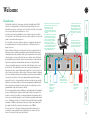
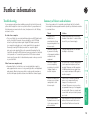
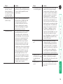
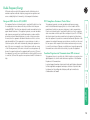
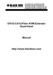
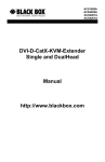
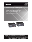
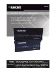
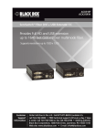
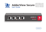
® ® NETWORK SERVICES FEBRUARY 2008 SW2007A-USB SW4007A-USB SW4007A-USB-PLUS ServSwitch™ Secure and Secure PLUS USER GUIDE 1 2 3 4 Secure Plus INSERT CARD CHIP DOWNWARDS CUSTOMER SUPPORT INFORMATION Order toll-free in the U.S.: Call 877-877-BBOX (outside U.S. call 724-746-5500) FREE technical support 24 hours a day, 7 days a week: Call 724-746-5500 or fax 724-746-0746 Mailing address: Black Box Corporation, 1000 Park Drive, Lawrence, PA 15055-1018 Web site: www.blackbox.com • E-mail: [email protected] ERR PWR Contents Further information Troubleshooting.........................................................................15 Summary of threats and solutions.............................................15 Getting assistance.......................................................................17 Safety information.....................................................................18 Certification notice for equipment used in Canada.................18 Radio Frequency Energy............................................................19 Normas Oficiales Mexicanas (NOM) Instrucciones de seguridad...............................................20 BlackBox subsidiary contact details...........................................22 Locations.......................................................................................5 Cabling recommendations...........................................................5 Tamper-evident seals....................................................................5 Links overview..............................................................................5 Mounting......................................................................................6 Making connections.....................................................................7 Connections to computer systems ........................................7 Connections to user console peripherals................................9 Connection to power supply.................................................12 Installation Tamper-evident seals..................................................................13 Selecting computers...................................................................13 Error indicator............................................................................13 Smart card reader.......................................................................14 Using the smart card reader..................................................14 Smart card security................................................................14 Custom configuration service...............................................14 Introduction..................................................................................2 ServSwitch Secure and Secure PLUS - features...........................3 Standard items..............................................................................4 Additional items...........................................................................4 Operation Welcome ® Welcome ® PC 1 2 3 PC 2 4 PC 3 PC 4 Individually colored indicators provide clear visual feedback about the currently selected channel Channel switching is by physical button press only, no keyboard or mouse codes are permitted Hard wired Data Diodes enforce a one-way flow on information The switching section is hard wired to allow only one channel to be selected at any time. This operation is also closely monitored by separate checking circuitry. 1 Common keyboard, mouse, video monitor and speakers are able to access multiple high security computers/networks, safe in the knowledge that data will not be transferred from one to another, either by user error or subversive attack. Various strategies are employed to ensure complete separation between the switched channels: • Data Diodes are used on all communication lines so that information cannot be made to flow the ‘wrong way’ by any compromised peripheral. • The keyboard and mouse are powered down and re-initialised during every channel switch to ensure that they cannot act as transport media for malicious data between computers. • Many aspects of operation are internally monitored. For instance, if a second channel attempts to open while another is still active, all operation will be instantly halted and an error condition signalled to the user. The Black Box ServSwitch Secure range of products are highly robust KVMA switches for critical applications. When information absolutely must not be leaked between systems or networks, the Secure and Secure PLUS units combine the necessary isolation with a desirable ease of use. ServSwitch Secure units are available in two port and four port versions while the ServSwitch Secure PLUS provides four ports with the addition of a smart card reader for user authentication purposes. The ServSwitch Secure units combine a number of overlapping strategies that are designed and proven to defeat potential points of infiltration or protect against user error. Firstly, all channel switching is controlled only from the front panel buttons. No keyboard or mouse switching commands are permitted and all operations are continually monitored by a dedicated sub-system. Any deviation from a strictly ordered sequence of events will result in an error condition, where all channels are immediately isolated and the operator is informed via a front panel indicator. Data Diodes, implemented within hardwired electronic circuitry, rather than software, are liberally employed to ensure that critical data paths can flow only in one direction. These data diodes ensure that a compromised peripheral, a keyboard for instance, cannot read information back from a connected system in order to transfer such details to another system. Whenever a channel is changed, the connected keyboard and mouse are always powered down and re-initialised to provide yet another level of protection against hidden peripheral malware. In general, the role of software within the unit has been reduced to an absolute minimum to avoid the possibility of subversive reprogramming. Additionally, all flash memory has been banished from the design, to be replaced by one time programmable storage which cannot be altered. The outer casing contains extensive shielding to considerably reduce electromagnetic emissions. Additionally, the casing has been designed with as few apertures as possible to reduce the possibility of external probing and several primary chassis screws are concealed by tamperproof seals to indicate any unauthorized internal access. Shielding extends also to the internal circuitry with all channels providing a minimum of 60dB crosstalk separation between computer input signals and any signals from the other computers at frequencies up to 100MHz. These are just a few of the many strategies and innovations that have been combined to ensure separation between differing systems. Numerous other defences lie in wait to defeat any potential threat. Introduction ServSwitch Secure and Secure PLUS - features ® 3 4 Secure Plus INSERT CARD CHIP DOWNWARDS ERR PWR Optional smart card reader The four port Secure PLUS model includes a smart card reader for use with user authentication schemes. 3 2 1 5V 4 INDOOR USE ONLY 2 Clear and simple connections All connections are clearly marked to avoid any ambiguity. Full dual link DVI/I video connections are provided and USB connections are used throughout for keyboard and mouse links. 2.0A 2 port version 2 1 5V 2.0A INDOOR USE ONLY USER CONSOLE 2 Switching is controlled solely by the clearly labeled front panel buttons Each selected channel is represented by an individually colored indicator to provide additional visual feedback. 2 port version 1 1 Clear error indication Any unexpected operation (such as an attempt to select two channels simultaneously) will be signalled by the ERR indicator, accompanied by complete isolation of all channels. Secure and shielded casing The casing is shielded to reduce electromagnetic emissions to an absolute minimum, access apertures are minimised and vital access screws are tamper-proofed. The ServSwitch Secure and Secure PLUS models are all housed in an electromagnetically shielded robust casing that measures just [w x d x h] 9.25” x 5.9” x 1.73” (235mm x 150mm x 44mm) - the height is 1U within a 19” rack. All channel switching is achieved solely using the front panel buttons which are clearly indicated, as are the rear panel connections. Additional items ® Standard items 1 2 3 S ServSwitch Secure or Secure PLUS Secu re P lus ER R PW R Audio cable Please contact Black Box for details Rack brackets Including four screws 5V, 2A Power supply plus country-specific mains cable CHINSE IP RT DO CA WN RD WA RD 10ft (3.0m) length - code: EHN900024U-010 DVI/I + USB cable assembly 6ft (1.8m) length - code: EHN900024U-006 4 Self adhesive feet Installation CD-ROM Installation The rear panel of the unit is well marked, however, the diagram below offers additional clarity on how best to arrange your connections. You may have noticed that the indicators on the front panel use different colors to represent the various channels. This is done to provide quick and effective visual feedback to the operator. Channel 1 has a green indicator and is traditionally used for the lowest security connection. The final channel, numbered 2 on the two port version and 4 of the four port version, uses a red indicator and is usually connected to the highest security connection. These are configuration conventions only and are offered as a suggestion - there are no technical differences in the operational specifications of the four channels. Please consider the following important points when planning the location of the ServSwitch Secure unit: • Situate the unit close to the host computers to which it will be connected and also the user console peripherals. • The unit requires a power supply input, so a nearby spare mains power outlet will be required. • As keyboard and mouse switching codes are not possible for security reasons, the only way to change channels is via the front panel buttons. Therefore, the unit should be easily accessible from the user’s normal position. • Please consult the precautions listed within the Safety information section. Links overview Locations ® Tamper-evident seals Given the high security nature of most installations that incorporate this unit, it may be a policy of your organisation to fit tamper-evident labels across certain seals and/or chassis screws. The unit assists in the use of tamper-evident seals in two ways: • All chassis retaining screws are countersunk so that their heads are flush with the outer covers, making it easy to apply seals across them. • The main cover is coated in a special matt finish that is particularly suited for contact with self-adhesive strip seals. 3 2 1 5V 2.0A Console connections Connect directly to the operator’s keyboard, mouse, video display and speakers. Channel 4 (red indicator) Usually used for connection to the highest security computer/ network. Channel 3 (amber indicator) On two channel models, this port is labeled 2 and uses a red indicator. Channel 2 (blue indicator) Channel 1 (green indicator) Usually used for connection to the lowest security computer/ network. 4 USER CONSOLE It is vitally important to use good quality shielded cables to minimise the risk of signal emissions that may be intercepted. Please follow the following recommendations when specifying cables: • DVI cables - should be braid and foil shielded. • VGA cables - should be braid and foil shielded. If DVI-I to VGA style adapters are used these should be of the fully ‘canned’ variety. • USB cables - should be braid and foil shielded. • Audio cables - should be braid shielded with fully shielded connectors (not unshielded connectors with drain wires). We strongly recommend that you fit ferrite cores at both ends of every cable to further assist with emission suppression. INDOOR USE ONLY Cabling recommendations Mounting ® NS OL E 4 1 5V 2.0 A CO ER INDOOR USE ONLY US The ServSwitch Secure unit offers two main mounting methods: • Supplied four self-adhesive rubber feet • Optional rack brackets Making connections ® Connections to the ServSwitch unit do not need to follow the precise order given in this user guide, although if one or more systems must be hot-plugged, connect these after all other connections have been made. IMPORTANT: All rear panel connectors are clearly marked, however, take great care not to cross connect any links or devices. You are recommended to connect all of the links within one channel before proceeding to the next channel. Note: In order to minimize signal emissions, you are strongly recommended to use good quality shielded cables throughout and to fit ferrite cores at each end of every cable. 2.0 A 5V 2.0 2 At the rear panel of the unit, choose the appropriate channel group (1 to 4) and connect a USB link cable (square type-B plug) to the socket marked 3 Attach the other end of the USB link cable to a vacant USB socket of the appropriate host computer (this will most probably require a rectangular type-A USB plug). Note: If the smart card reader is fitted and used, its signals will also be presented to the computer(s) via this common USB link. A 3 Attach the other end of the audio link cable to the speaker socket of the appropriate system. 1 INDOOR USE ONLY 5V INDOOR USE ONLY 2 1 2 To connect an audio link 1 Wherever possible, ensure that power is disconnected from the unit and the host computer(s) to be connected. 2 At the rear panel of the unit, choose the appropriate channel group (1 to 4) and connect an audio link cable to the socket marked To connect a keyboard and mouse link 1 Wherever possible, ensure that power is disconnected from the unit and the host computer(s) to be connected. Connections to computer systems Connections to computer systems (continued) ® Connecting video inputs 5V 2.0 2 1 5V 2.0 A Digital video input Analog video input A INDOOR USE ONLY 1 To connect an analog video input 1 Wherever possible, ensure that power is disconnected from the unit and the host computer(s) to be connected. 2 As appropriate, connect either a digital or analog video link cable to the required DVI/I socket on the rear panel: • Digital Connect a digital video link cable to the port labeled within the appropriate channel group on the rear panel. • Analog Connect a converter module to the port labeled within the appropriate channel group on the rear panel. Connect an analog video link cable to the converter module. In both cases, ensure that the securing screws are used to maintain reliable links. 3 Connect the plug at the other end of the cable to the corresponding video output socket of the appropriate host computer. 2 INDOOR USE ONLY The unit provides full DVI/I connections for video. This means that it can receive, and transfer, any VGA or DVI input (from analog to single or dual link digital) up to the following maximum resolutions and rates: • Analog: 1920 x 1200 x 60Hz • Single link digital: 1920 x 1200 x 60Hz (up to 165MHz pixel clock) • Dual link digital: 2560 x 1600 x 60Hz (up to two times 165MHz pixel clock) Generally, all inputs should be of the same type, i.e. all analog or all digital (and the monitor should correspondingly be of the correct type). However, there are certain situations where mixing of different video types is possible - contact technical support for more details. The use of DDC information (automatically provided by the video display) could cause issues in certain high security installations - please see the Video display (DDC) information section on page 10 for further details). Connections to user console peripherals ® To connect speakers 1 Wherever possible, ensure that power is disconnected from the unit and the host computer(s) to be connected. 2 At the far left side of the rear panel, connect the speaker cable to the socket marked ER CO NS OL E NS OL E US CO ER US To connect a keyboard and mouse Note: The ServSwitch Secure unit can directly accommodate only a USB-style keyboard and mouse. If required, you can use suitably shielded conversion cables to connect peripherals that have PS/2-style interfaces. 1 Wherever possible, ensure that power is disconnected from the unit and the host computer(s) to be connected. 2 At the far left side of the rear panel, connect the cables from the keyboard and mouse to the USB sockets marked and respectively. Connecting video inputs CO NS OL E ER US US ER CO NS OL Digital video display output E To connect an analog video input 1 Wherever possible, ensure that power is disconnected from the unit and the host computer(s) to be connected. 2 As appropriate, connect either a digital or analog video display to the DVI/I socket on the far left side of the rear panel: • Digital Connect the digital video display cable to the port labeled within the user console section on the rear panel. • Analog Connect a converter module to the port labeled within the user console section on the rear panel. Connect the analog video display cable to the converter module. In both cases, ensure that the securing screws are used to maintain reliable links. 3 Connect the plug at the other end of the cable to the corresponding video output socket of the appropriate host computer. ® Analog video display output The unit provides full DVI/I connections for video. This means that it can receive, and transfer, any VGA or DVI input (from analog to single or dual link digital) up to the following maximum resolutions and rates: • Analog: 1920 x 1200 x 60Hz • Single link digital: 1920 x 1200 x 60Hz (up to 165MHz pixel clock) • Dual link digital: 2560 x 1600 x 60Hz (up to two times 165MHz pixel clock) Generally, all inputs should be of the same type, i.e. all analog or all digital (and the monitor should correspondingly be of the correct type). However, there are certain situations where mixing of different video types is possible - contact technical support for more details. The use of DDC information (automatically provided by the video display) could cause issues in certain high security installations - please see the Video display (DDC) information section on page 10 for further details). 10 ServSwitch Secure unit response Connected DDC data is harvested from the connected video display during unit power on and written to all computer port memories. Not connected Unit retains the DDC data that is already held in the port memories and continues to present them to the attached computers. No new DDC data can be sought from the currently connected video display. Grounded Unit wipes all DDC data held in memory and presents no information to the attached computers. In situations where no DDC information is being supplied, it may be necessary to use a special driver on the connected computers to inform their graphic adapters on the appropriate signals to send. Alternatively, a ‘surrogate’ video display of the appropriate type could be temporarily connected to the ServSwitch Secure unit in order to harvest the necessary DDC information. The surrogate video display could then be replaced by the real one, which has its DDC pin disconnected (not grounded). DDC pin conditions ServSwitch Secure DDC policy The ServSwitch Secure maintains individual DDC memories for each connected computer port. During manufacture, these DDC memories are each loaded with a set of default DDC data. When the ServSwitch is powered on, its response will be determined by the condition of the DDC signalling pins of the video monitor connector: • If the DDC pins are connected as standard: the ServSwitch Secure reads the DDC data from the attached video monitor and loads a copy into each port memory, which can then be made available to the connected computers. • If no video monitor is connected or the monitor’s DDC signalling pins are disconnected: The ServSwitch Secure will maintain the default data held in the DDC memories and make them available to the computers. • If the video monitor’s DDC signalling pins have been connected to ground: The ServSwitch Secure will load a set of default data to the DDC memories and no DDC data will be made available to the computers. This provides a means of clearing DDC information about previously attached monitors. Note: Most analog video cards will output a video signal without DDC information. In such installations it may be acceptable to disconnect the DDC connections from the ServSwitch Secure so that no DDC information is made available to the computers. However, most DVI graphics cards will not output a video signal unless they can read the DDC information. ® To determine how DDC data is used Note: The information given here is provided purely as an overview. It is beyond the scope of this document to provide detailed instructions on how to modify video display cables, which should only be attempted by a qualified engineer. If the transfer of DDC information is unsuitable for your installation, you can take steps to bypass or disable its use. DDC data is sent from the video display on the following pins of their connectors: • Analog VGA (15-pin D-type) connector: pins 12 and 15 • Digital DVI connector: pins 6 and 7 As mentioned earlier, the ServSwitch Secure unit responds in the different ways, depending upon how the DDC data lines within the video display cable have been wired: The Display Data Channel (or DDC) scheme was introduced to allow analog and digital video displays to provide details about themselves and their capabilities to the computer’s graphic adapter circuitry. In most applications this is a useful and positive feature. However, in a highly secure environment this presents two potential problems: • Most video displays provide manufacturer, model and serial number information as part of their DDC data. This unique information could possibly be used as a marker by anyone attempting to compromise security within one or more of the connected computers/networks. • The operation of the DDC scheme could theoretically provide a means to transfer a small 128 byte packet of data to the computers at each power on cycle of the ServSwitch. If your organisation wishes to protect against such scenarios then it is recommended that the DDC lines are disconnected in the cable between the ServSwitch and the monitor. Alternatively, Black Box would be happy to discuss configuring the ServSwitch with a DDC policy to suit your organisation. Video display (DDC) information 11 Connection to power supply ® A 2 When all other connections have been made, connect the main body of the power supply to a nearby earthed mains socket. 2.0 5V 1 INDOOR USE ONLY 2 To connect the power supply 1 Attach the output connector of the power supply (country specific power supplies are available) to the socket on the far right of the rear panel. Important: Please read and adhere to the electrical safety information given within the Safety information section of this guide. In particular, do not use an unearthed power socket or extension cable. 12 Operation ® In operation, the ServSwitch Secure unit allows you to quickly and securely switch between up to four systems. Strictly only one system may be accessed at a time, whereupon the common keyboard and mouse are linked to that system. Tamper-evident seals In order to guard against the possibility of malicious software and also to minimize the chance of accidental switching, the ServSwitch Secure unit offers only one method to change between channels. All switching is done using the front panel switches. 3 4 Secure ERR PWR • The buttons are clearly labeled to eliminate any ambiguity. • Press the appropriate button to select the labeled channel. • When the chosen channel has been connected, the adjacent indicator will illuminate (continuously) to confirm. If the indicator flashes, then the selected computer is either switched off or disconnected. • Each channel uses a differently colored indicator to provide additional visual feedback about the chosen channel. Channel 1 has a green indicator and is generally configured to link with the lowest security computer/network, whereas channel 4 (or channel 2 on two-port versions) has a red indicator and is generally configured to link with the highest security computer/ network. 2 The red error indicator is located on the right side of the front panel and is labeled ERR. Separate microprocessors monitor each channel and any of them can trigger an error state if they detect unexpected or unauthorized operations. If the ERR indicator illuminates, you will need to first locate and confirm the source of the fault. Then you will need to either power cycle the offending computer or remove and replace its USB connection to the ServSwitch Secure. Error indicator Selecting computers 1 Given the high security nature of most installations that incorporate this unit, it may be a policy of your organisation to fit tamper-evident labels across certain seals and/or chassis screws. As part of a best practice policy, you are recommended to check any applied seals on a regular basis to ensure that the unit has not been opened without authorization. 13 Smart card reader ® Using the smart card reader The instructions given here are general advice and may be superseded by procedures stipulated by your organization. Note: The channel can be changed before or after inserting the smart card. To use the smart card reader 1 Align your smart card with the reader slot located in the front panel of the unit. Ensure that the gold contacts of the card are facing down. 2 Press the required channel select button (if the required channel is not already selected). 3 Follow the on screen instructions issued by the selected computer. For larger installations we offer a custom configuration service where the ServSwitch Secure PLUS can be internally altered to accommodate particular requirements. In situations where a card reader is required only for some of the networks linked to the ServSwitch Secure PLUS, we can irrevocably disable the card access abilities of any channel to suit. Other custom configurations are available to order. Custom configuration service ERR PWR Secure Plus INSERT CARD CHIP DOWNWARDS Due to the functions fulfilled by smart cards, it is necessary to grant them two-way data flow, rather than restricting data to a single direction as imposed within all other areas of the ServSwitch Secure PLUS. This means that data can potentially be read from and written to the smart card. The Secure Switch PLUS emulates the same action as unplugging the card from one computer’s card reader and plugging it into the next computer’s card reader. The Secure Switch does not restrict or interfere with the encrypted communication between the computer and the smart card. The protection against data leakage between computers by means of storage of data within a smart card must therefore be provided by the smart card software in the same way that such protection would need to be provided if multiple card reader units were connected to the computers. The ServSwitch Secure cards reader circuitry works in the following way: • Every computer channel within the ServSwitch Secure PLUS has its own dedicated smart card reader circuit to which the smart card socket is connected only when the relevant channel is selected. • When the channel is switched, the smart card socket is first powered down and then completely re-initialized for each new channel. Smart Card Security The ServSwitch Secure PLUS models include a smart card reader which allows you to insert your security card for authorization. 14 Further information Video from some computers only • Remember that the ServSwitch does not convert digital video signals to analog signals and vice versa so it is not generally possible to mix digital and analog inputs. Mixed systems are possible in certain special circumstances but these will require specialist assistance from Black Box technical support. Microprocessor malfunction or unanticipated software bugs causing data to flow between ports. Unidirectional data flow is enforced by hardware “data diodes” so data isolation doesn’t rely on software integrity. Subversive snooping by means of detecting electromagnetic radiation emitted from the equipment. Carefully shielded metal case with dual shielding in critical areas. Detection of signals on one computer by monitoring for crosstalk (leakage) signals on another computer. No connections to sensitive analog inputs (such computer microphone ports) are provided. Minimum crosstalk separation of 60dB provided between signals from one computer and input or I/O signals to another computer. Malicious modification of microprocessor software causing data to leak between ports. Data isolation is assured by hardware and so is not compromised by any changes to the microprocessor software. Microprocessors use one time programmable memory so flash upgrades are not possible. Case uses counter-sunk screws which can be protected by tamper proof seals. Buffered data within a keyboard or mouse is sent to the wrong computer after switchover. Keyboard and mouse are powered down and reset between each switchover to ensure that all buffers are cleared out. Solution Threat No video from computer • This is most likely to be associated with having the wrong DDC data loaded into the ServSwitch. Computers often need read the correct DDC data before they will output a video signal. If digital DDC data is presented to a computer’s analog video port, a video signal will not be generated. Conversely, if analog DDC data is presented to a computer’s digital video port, a video signal will also not be generated. Remember that the ServSwitch only reads the DDC data from your monitor when the ServSwitch is first powered on. To ensure that your monitor’s DDC data is read and stored correctly, ensure that it is attached and powered on when you switch on your ServSwitch. This section provides a list of potential security threats that the ServSwitch Secure might face during operation and the special steps that have been taken to counteract them. If you experience problems when installing or using the ServSwitch Secure unit, please check through this section for a possible solution. If your problem is not listed here and you cannot resolve the issue, then please refer to the ‘Getting assistance’ section. Summary of threats and solutions Troubleshooting ® 15 Channel switching is controlled by the front panel buttons only with all keyboard hotkey or mouse switching capabilities removed from the design. Forced malfunctions due to overloaded signaling. Data transfer by means of common storage. USB ports support keyboard and mouse (and card reader for SW4007-PLUS-USB) connections only. The product does not enable a USB memory stick or disk drive to be shared between computers. Unidirectional signalling protects against data transfer across the switch. Timing analysis attacks. If a connection exists between a computer and a shared microprocessor system, it is potentially possible to determine what may be happening on the micro by timing the responses to repeated requests that the micro must service. For example, if a high data bit takes longer to transmit through the system than a low bit it may be possible to detect the pattern of data flowing between other ports by attempting to time the responses to otherwise normal requests. In the ServSwitch Secure, each port has a dedicated processor that only has input signals from the rest of the system. These input signals are only active when the port is selected. Consequently a timing analysis attack from one computer would yield no information about data flowing to another computer. It is potentially possible to create forced malfunctions by constantly and quickly sending a stream of valid requests (such as the request to update the keyboard lights). A well known example of an undesirable KVM malfunction is a “crazy mouse” which was quite common with early KVM switches and was caused by data loss on PS/2 systems with the result that the mouse darted around the screen randomly clicking and opening windows. The unidirectional design of the Secure Switch ensures that the influence of signalling on one port cannot flow past the data diodes. This means that overload signalling on one port will not affect the operation of another port. USB signalling is not susceptible to the failure mechanism that caused the crazy mouse on PS/2 systems. The user selects the wrong port. Only one simple method of selecting computers is provided. The selected port is clearly and unambiguously indicated on the front panel by means of colored lights adjacent to each key switch. For high levels of security, the screens of high and low security computers should be arranged to look visibly different in general appearance. Signalling by means of shorting the power supply or loading the power supply. Each port is independently powered by its USB port. Shorting the power supply on one port will not cause the power on other ports to be switched off. Tampering with the switch. The switch is designed to enable tamper proof seals to be fitted over the countersunk screws. Data being sent to ports by means of faulty or subverted keyboards or mice causing the channel to switch and sending data in turn to each port. ® Solution Threat Solution Threat 16 Getting assistance ® in the US: in the UK: 724-746-5500 +44 (0)118 965 6000 • Phone [email protected] [email protected] in the US: in the UK: • Email If you are still experiencing problems after checking the list of solutions in the Troubleshooting section then we provide a number of other solutions: 17 The Canadian Department of Communications label identifies certified equipment. This certification means that the equipment meets certain telecommunications-network protective, operation, and safety requirements. The Department does not guarantee the equipment will operate to the user’s satisfaction. Before installing this equipment, users should ensure that it is permissible to be connected to the facilities of the local telecommunications company. The equipment must also be installed using an acceptable method of connection. In some cases, the company’s inside wiring associated with a single-line individual service may be extended by means of a certified connector assembly (extension cord). The customer should be aware that compliance with the above conditions may not prevent degradation of service in some situations. Repairs to certified equipment should be made by an authorized Canadian maintenance facility—in this case, your supplier. Any repairs or alterations made by the user to this equipment, or equipment malfunctions, may give the telecommunications company cause to request the user to disconnect the equipment. Users should ensure for their own protection that the electrical ground connections of the power utility, telephone lines, and internal metallic water pipe system, if present, are connected together. This precaution may be particularly important in rural areas. CAUTION: Users should not attempt to make such connections themselves, but should contact the appropriate electric inspection authority, or electrician, as appropriate. ® • For use in dry, oil free indoor environments only. • Not suitable for use in hazardous or explosive environments or next to highly flammable materials. • Warning – the optional power adapter contains live parts. • No user serviceable parts are contained within the optional power adapter - do not dismantle. • Do not use the power adapter if the power adapter case becomes damaged, cracked or broken or if you suspect that it is not operating properly. • Replace the power adapter with a manufacturer approved type only. • If you use a power extension cable, make sure the total ampere rating of the devices plugged into the extension cable do not exceed the cable’s ampere rating. Also, make sure that the total ampere rating of all the devices plugged into the wall outlet does not exceed the wall outlet’s ampere rating. • Do not attempt to service the unit yourself. • The power adapter can get warm in operation – do not situate it in an enclosed space without any ventilation. • The unit does not provide ground isolation and should not be used for any applications that require ground isolation or galvanic isolation. • When using the power adapter, use only with a grounded outlet. Certification notice for equipment used in Canada Safety information 18 Radio Frequency Energy ® All interface cables used with this equipment must be shielded in order to maintain compliance with radio frequency energy emission regulations and ensure a suitably high level of immunity to electromagnetic disturbances. This equipment generates, uses and can radiate radio frequency energy and if not installed and used properly, that is, in strict accordance with the manufacturer’s instructions, may cause interference to radio communication. It has been tested and found to comply with the limits for a class A computing device in accordance with the specifications in Subpart J of part 15 of FCC rules, which are designed to provide reasonable protection against such interference when the equipment is operated in a commercial environment. Operation of this equipment in a residential area may cause interference, in which case the user at his own expense will be required to take whatever measures may be necessary to correct the interference. Changes or modifications not expressly approved by the manufacturer could void the user’s authority to operate the equipment. This equipment does not exceed the class A limits for radio noise emissions from digital apparatus set out in the radio interference regulations of the Canadian Department of Communications. Le présent appareil numérique n’émet pas de bruits radioélectriques dépassant les limites applicables aux appareils numériques de la classe A prescrites dans le règlement sur le brouillage radioélectriques publié par le ministère des Communications du Canada. Canadian Department of Communications RFI statement This equipment has been tested and found to comply with the limits for a class A computing device in accordance with the specifications in the European standard EN55022. These limits are designed to provide reasonable protection against harmful interference. This equipment generates, uses and can radiate radio frequency energy and if not installed and used in accordance with the instructions may cause harmful interference to radio or television reception. However, there is no guarantee that harmful interference will not occur in a particular installation. If this equipment does cause interference to radio or television reception, which can be determined by turning the equipment on and off, the user is encouraged to correct the interference with one or more of the following measures: (a) Reorient or relocate the receiving antenna. (b) Increase the separation between the equipment and the receiver. (c) Connect the equipment to an outlet on a circuit different from that to which the receiver is connected. (d) Consult the supplier or an experienced radio/TV technician for help. FCC Compliance Statement (United States) European EMC directive 89/336/EEC 19 Normas Oficiales Mexicanas (NOM) electrical safety statement 15En caso de existir, una antena externa deberá ser localizada lejos de las lineas de energia. 16El cable de corriente deberá ser desconectado del cuando el equipo no sea usado por un largo periodo de tiempo. 17Cuidado debe ser tomado de tal manera que objectos liquidos no sean derramados sobre la cubierta u orificios de ventilación. 18Servicio por personal calificado deberá ser provisto cuando: A: El cable de poder o el contacto ha sido dañado; u B: Objectos han caído o líquido ha sido derramado dentro del aparato; o C: El aparato ha sido expuesto a la lluvia; o D: El aparato parece no operar normalmente o muestra un cambio en su desempeño; o E: El aparato ha sido tirado o su cubierta ha sido dañada. 1 Todas las instrucciones de seguridad y operación deberán ser leídas antes de que el aparato eléctrico sea operado. 2 Las instrucciones de seguridad y operación deberán ser guardadas para referencia futura. 3 Todas las advertencias en el aparato eléctrico y en sus instrucciones de operación deben ser respetadas. 4 Todas las instrucciones de operación y uso deben ser seguidas. 5 El aparato eléctrico no deberá ser usado cerca del agua—por ejemplo, cerca de la tina de baño, lavabo, sótano mojado o cerca de una alberca, etc. 6 El aparato eléctrico debe ser usado únicamente con carritos o pedestales que sean recomendados por el fabricante. 7 El aparato eléctrico debe ser montado a la pared o al techo sólo como sea recomendado por el fabricante. 8 Servicio—El usuario no debe intentar dar servicio al equipo eléctrico más allá a lo descrito en las instrucciones de operación. Todo otro servicio deberá ser referido a personal de servicio calificado. 9 El aparato eléctrico debe ser situado de tal manera que su posición no interfiera su uso. La colocación del aparato eléctrico sobre una cama, sofá, alfombra o superficie similar puede bloquea la ventilación, no se debe colocar en libreros o gabinetes que impidan el flujo de aire por los orificios de ventilación. 10El equipo eléctrico deber ser situado fuera del alcance de fuentes de calor como radiadores, registros de calor, estufas u otros aparatos (incluyendo amplificadores) que producen calor. 11El aparato eléctrico deberá ser connectado a una fuente de poder sólo del tipo descrito en el instructivo de operación, o como se indique en el aparato. 12Precaución debe ser tomada de tal manera que la tierra fisica y la polarización del equipo no sea eliminada. 13Los cables de la fuente de poder deben ser guiados de tal manera que no sean pisados ni pellizcados por objetos colocados sobre o contra ellos, poniendo particular atención a los contactos y receptáculos donde salen del aparato. 14El equipo eléctrico debe ser limpiado únicamente de acuerdo a las recomendaciones del fabricante. Instrucciones de seguridad ® 20 Black Box Corporation, 1000 Park Drive, Lawrence, PA 15055-1018, United States of America Tel: +1-724-746-5500 Fax: +1-724-746-0746 © 2008 Black Box Corporation All trademarks are acknowledged. ® Documentation by: www.ctxd.com 21 BlackBox subsidiary contact details United States www.blackbox.com 724-746-5500 724-746-0746 Austria www.black-box.at [email protected] +43 1 256 98 56 +43 1 256 98 56 Belgium www.blackbox.be [email protected] [email protected] [email protected] +32 2 725 85 50 +32 2 725 92 12 Denmark www.blackbox.dk [email protected] +45 56 63 30 10 +45 56 65 08 05 Finland www.blackbox.fi [email protected] +35 201 888 800 +35 201 888 808 France www.blackbox.fr [email protected] +33 1 45 606 717 +33 1 45 606 747 Germany www.black-box.de [email protected] +49 811 5541 110 +49 811 5541 499 Italy www.blackbox.it [email protected] +39 02 27 404 700 +39 02 27 400 219 Netherlands www.blackbox.nl [email protected] +31 30 241 7799 +31 30 241 4746 Norway www.blackboxnorge.no [email protected] +47 55 300 710 +47 55 300 701 Spain www.blackbox.es [email protected] +34 9162590732 +34 916239784 Sweden www.blackboxab.se [email protected] +46 8 44 55 890 +46 08 38 04 30 Switzerland www.black-box.ch [email protected] +41 55 451 70 71 +41 55 451 70 75 UK www.blackbox.co.uk [email protected] +44 118 965 6000 +44 118 965 6001 Ireland www.blackbox.co.uk [email protected] +353 1 662 2466 +353 1 662 2477 Fax Phone Web Site/Email Country ® 22