1
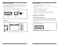
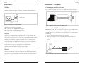
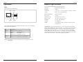
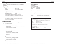
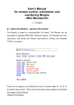
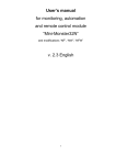
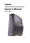
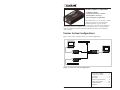
NETWORK SERVICES
LE180A 10Base-T Transceiver
• Stand-Alone model
• Attached Unit Interface (AUI) to
Ethernet RJ-45 connectors
• No external power requirement
The LE180A transceiver is a media access unit
(MAU) that connects the AUI port of data
terminal equipment, repeaters, or other
network devices either directly or through an
AUI cable to an Ethernet 10BASE-T device. The Ethernet device is connected to the
transceiver through an unshielded or shielded twisted-pair copper cable with RJ-45
connector ends.
Various System Configurations
Figure 1 shows various examples of transceiver system configurations.
10-Base-T Hub
Workstation
Black Box
Transceiver
Or
Or
Black Box
Transceiver
Workstation
Black Box
Transceiver
HUB with AUI Port
Figure 1: Transceiver System Configurations
General Description . . . . . . .2
Connectors & Cables . . . . . . .3
Installation . . . . . . . . . . . . . .6
Operations . . . . . . . . . . . . . .8
Technical Specifications . . . .9
Cable Specifications . . . . . .10
Troubleshooting . . . . . . . . .10
Contact Us . . . . . . . . . . . . .11
LE180A
LE180A
General Description
LE180A Features
The LE180A IEEE802.3 compliant Ethernet transceiver uses 10Mbps Ethernet
CSMA/CD protocol to provide a connection interface to 10Base-T Ethernet unshielded
twisted-pair (UTP) cables. The transceiver connects to the AUI connector of an
Ethernet device via standard AUI cable.
• Provides a complete interface of the AUI to Ethernet UTP cable.
Figure 2: shows the front and rear panels of the LE180A transceiver.
• Drives UTP cable segments up to 100 meters (328ft).
• Supports 10Mbps data transfer rates.
• Supports Carrier Sense Multiple Access/Collision Detection (CSMA/CD) contention
protocol.
• Supports selectable link and SQE test functions.
4 LEDs
Rear
• Supports direct connections to host AUI ports.
Front
• Detects and corrects reverse polarity on the receiving pair of UTP cables.
3-Position
Switch
• Provides four LEDs: Transmit (TX), Receive (RX), Collision, and Status.
!
Connectors
and Cables
AUI Connector
RJ-45 Connector
LE180A
AUI male connector
!
AUI D-sub 15-pin male connector accommodates AUI drop cables (50 meters max.).
The AUI connector is used to connect the transceiver to the AUI port of an Ethernet
device such as an Ethernet MAC controller, a repeater, or a hub via an AUI drop cable.
The AUI connector is shown in Figure 4. The AUI male connector pin assignments are
show in Table 1.
Figure 2: LE180A Transceiver Front and Rear Panels
Dimensions
Figure 3 shows the LE180A dimensions.
D-Sub 15-pin Male AUI Connector
3.141
0.812"
1
8
1.757"
9
15
Figure 4: LE180A AUI Male Connector Pin Assignments
Figure 3: LE180A Dimensions
2
Black Box Network Services, 724-746-550, www.blackbox.com
Black Box Network Services, 724-746-550, www.blackbox.com
3
LE180A
LE180A
Connectors & Cables -- Continued
AUI connector -- continued
Table 1: AUI Male Connector Pinouts
Pin Name
Pairs
Use
3 DO +
Transmit
Data Out +
10 DO Pair
Data Out 11 DO S
Data Out Shield
5 DI +
Receive
Data In +
12 DI Pair
Data In 4 DI S
Data In Shield
7 CO +
Option
Control Out +
15 CO Pair
Control Out 8 CO S
Control Shield
2 CI +
Collision
Control In +
9 CI Pair
Control In 1 CI S
Control Shield
6 VC
Power
Voltage Common
13 VP
Pair
Voltage Plus
14 VS
Voltage Shield
UTP cable (RJ-45 connector)
Connectors & Cables -- continued
UTP cable (RJ-45 connector) -- continued
Table 2:
Pin
1
2
3
4
5
6
7
8
RJ-45 Pin Assignments
Out Jack Assignments
Outgoing Data 1 (+)
Outgoing Data 2 (-)
Incoming Data 1 (+)
Not connected
Not connected
Incoming Data 2 (-)
Not connected
Not connected
Wiring schemes for UTP cable and devices
How to install the UTP cable is determined by the characteristics of the 10Base-T UTP
port of the other device. The following shows some pinning examples:
UTP Cable Pin Wiring
Transceiver
The 10Base-T, RJ-45 out jack is used to connect a 10Base-T Ethernet device via a
2-pair UTP cable. (Use category 3, 4, or 5 UTP cable.) The length of the UTP
cable can be up to 100m (328ft).
The RJ-45 connector pin configuration is shown in Figure 5. The pin assignments
are show in the Table 2..
2
1
3
4
5
Transceiver
6
Pin
1
2
3
6
Pin
1
2
10Base-T Device Input
3
6
Pin
1
2
3
6
Pin
3
10Base-T Output Jack
6
Computer 10Base-T Port
1
Transceiver
2
7
8
Note:
The device 10Base-T output jack is normally used to connect to another
10Base-T device. The vendor's 10Base-T device sometimes provides a
crossover option to set the jack as an input jack for connecting to a 10Base-T
Ethernet station.
Figure 5: RJ-45 Connector Pin Configuration
4
Black Box Network Services, 724-746-550, www.blackbox.com
Black Box Network Services, 724-746-550, www.blackbox.com
5
LE180A
LE180A
Installation
Installation -- Continued
Connecting to a Device AUI port
Switches
The LE180A has a 3-position DIP switch. See Figure 6. Two of the switches provide
options for enabling and disabling the SQE test and LINK test functions. Both test
functions are Ethernet and 10Base-T standards.
SW1
SW2
The LE180A can connect to any Ethernet device with an AUI port. To connect to a
device with an AUI port, an AUI cable or direct connection is required. See Figure 7.
SW3
AUI Cable Length 50 Feet Maximum
AUI
3-Position Switch
Front
Figure 6: LE180A Three-Position Switch
The following describes the switch settings:
Black Box
Transceiver
Figure 7: LE180A Connected to an AUI Device Port
SW1 = SQE test: UP is enabled/DOWN is disabled
Connecting to an RJ-45 device jack
SW2 = Link test: UP is enabled/DOWN is disabled
SW3 = Duplex: UP is half/DOWN is full
IMPORTANT: If the transceiver is attached to an Ethernet repeater, a10Base-T hub,
or a wiring concentrator, the SQE test function should be disabled.
SQE test
To connect the transceiver to a 10Base-T device via RJ-45 jacks, see Figure 8 and do
the following:
The transceiver is shipped from the factory with the SQE test switch enabled. SQE
(Signal Quality Error) is the IEEE term for collisions. Depending on the Ethernet
device attached to the AUI connector, set the SW “1” to the DOWN position to disable
the SQE test function or to the "UP" position to enable the test.
The SQE Test (heartbeat) is a means of detecting a transceiver’s inability to detect
collisions. Without this test, it would not be possible to determine if the collision
detector is operating properly. The SQE test starts by generating a test signal on the
collision pair from the transceiver (or its equivalent) following every transmission on
the network. It does not generate any signals on the common medium.
1. Select an appropriate length UTP cable for the connection.
2. Connect one end of the UTP cable to the RJ-45 OUT jack of the transceiver.
3. Route the free end of the UTP cable to the area where the10Base-T device is
located.
4. Connect the free end of the UTP cable to an RJ-45 IN jack on the 10Base-T device.
Hub
RJ-45 Plug
Additionally, IEEE 802.3 specifications state that IEEE 802.3 compliant repeaters
must not be attached to transceivers that generate the heartbeat.
Link test
For UTP port connection, the LE180A implements the link integrity test functions as
specified in the IEEE 802.3 10Based-T standard. The LE180A will transmit link test
pulses to any UTP port after that port’s transmitter is inactive for a range of 8 to 17 ms.
These pulses are sent to confirm that a valid connection exists between the LE180A
and its attached device.
6
Black Box Network Services, 724-746-550, www.blackbox.com
AUI Cable
UTP Cable
Black Box
Transceiver
10Base-T
Port
Figure 8: LE180A Connected to a RJ-45 Device Jack
Black Box Network Services, 724-746-550, www.blackbox.com
7
LE180A
LE180A
Operations
Technical Specifications
For use with Black Box Model LE180A or equivalent.
LEDs
Figure 9 shows the LE180A LEDs:
Status
Collision
Receive
Transmit
Figure 9: LE180A LEDs
The LE180A LEDs display the operational status of the transceiver. The following
table explains LED indications.
LED
Collision
Status
Transmit
Receive
Description
Blinks when detects a collision
ON Solid:
UTP link established
Blinks:
No UTP link
5-Blink pattern: UTP polarity reversal*
Blinks when transmitting data on the RJ-45 cable
Blinks when receiving data on the RJ-45 cable
Standards
IEEE 802.3ab, IEEE 802.3
Data Rate
10 Mb/s
Dimensions
1.77" x 0.81” x 3.14" (44.96 mm x 20.57mm x 79.76mm)
Weight
0.2 lbs. (90.72 g) approximately
Power Consumption
500mA @ 12VDC
Power Source
AUI port
Operating Temp
0 to 50°C (32°F to 122°F )
Storage Temp:
-25 to 85°C (-13°F to 185°F )
Humidity:
5 to 95%, non-condensing
Altitude:
0 to 10,000 feet
MTBF:
125,126 Bellcore hours. Calculated at 40C with a 10C
temperature rise.
IMPORTANT Copper based media ports: e.g., Twisted Pair (TP) Ethernet, USB,
RS232, RS422, RS485, DS1, DS3, Video Coax, etc. are intended connecting to intrabuilding (inside plant) link segments, not subject to lightening transients or power
faults. Copper based media ports: e.g., Twisted Pair (TP) Ethernet, USB, RS232,
RS422, RS485, DS1, DS3, Video Coax, etc. are NOT for connecting inter-building
(outside plant) link segments that are subject to lightening transients or power faults.
Failure to observe this notice could result in damage to equipment.
*Note: The LE180A corrects reverse polarity on its receiving port UTP cable
automatically.
8
Black Box Network Services, 724-746-550, www.blackbox.com
Black Box Network Services, 724-746-550, www.blackbox.com
9
LE180A
LE180A
Cable Specifications
Contact Us
The physical characteristics of the media cable must meet or exceed IEEE 802.3
specifications.
Black Box, Headquarters
Copper cables
Lawrence, PA 15055-1018
1000 Park Drive
Category 3: (minimum requirement)
Gauge
Attenuation
Maximum cable distance:
By Telephone:
877-877-2269
24 to 22 AWG
11.5 dB/100m @ 5-10 MHz
100 m
By Fax:
724-746-0746
By E-mail:
[email protected]
Category 5: (recommended)
Gauge
Attenuation
Maximum cable distance:
24 to 22 AWG
22.0 dB/100m @ 100 MHz
100 m
Technical Support
• Straight-through or crossover twisted-pair cable may be used.
• Shielded (STP) or unshielded (UTP) twisted-pair cable may be used.
• Pins 1&2 and 3&6 are the two active pairs in an Ethernet network .
• RJ-45 Pin-out: Pin 1 = TD+, Pin 2 = TD-, Pin 3 = RD+, Pin 6 = RD• Use only dedicated wire pairs for the active pins:
(e.g., blue/white & white/blue, orange/white & white/orange, etc.)
• Do not use flat or silver satin wire.
Technical support is available 24 hours a day.
U.S.A:
Fax:
Website:
724 746-5500
800-321-0746
www.blackbox.com/Tech_Support/Index.aspx#
NETWORK SERVICES
Declaration of Conformity
Name of Mfg:
Troubleshooting
If the transceiver fails, determine the answer to the following questions:
1.
Is the status LED flashing?
NO
•
Verify that the AUI device is turned ON.
•
Verify that the AUI cable from the transceiver to the AUI device port is
installed properly.
•
Contact Tech Support: 724 746-5500.
YES
•
Go to step 2.
2.
Is the RX LED flashing (receiving data)?
NO
•
Is the LED ON Solid?
•
Check twisted pair cable for proper connection
•
Contact Tech Support: 724 746-5500.
Yes
Go to step 3.
3.
Is the TX LED ON?
NO
•
Check twisted pair cable for proper connection.
•
Is the LED flashing (transmitting data)?
•
Restart the hardware to force re-initialization.
•
Contact Tech Support: 724 746-5500.
Yes
•
Contact Tech Support: 1724 746-5500.
10
Black Box Network Services, 724-746-550, www.blackbox.com
Black Box Network Services
Black Box, 1000 Park Drive Lawrence, PA 15055-1018 U.S.A.
Model:
LE180A Transceiver
Part Number(s):
LE180A
Regulation:
EMC Directive 89/336/EEC
Purpose: To declare that the LE180A Transceiver to which this declaration refers is
in conformity with the following standards.
EN55022:1998 + A1:2000 + A1:2003 EN 55024:1998 + A1:2000 + A2:2003
I, the undersigned, hereby declare that the equipment specified above conforms to the above
Directive(s) and Standard(s).
May, 2007_____
Stephen Anderson, Vice-President of Engineering
Date
Black Box Network Services, 724-746-550, www.blackbox.com
11
LE180A
Compliance Information
CE Mark
FCC regulations
This equipment has been tested and found to comply with the limits for a Class A digital device,
pursuant to part 15 of the FCC rules. These limits are designed to provide reasonable protection
against harmful interference when the equipment is operated in a commercial environment. This
equipment generates, uses, and can radiate radio frequency energy and, if not installed and used in
accordance with the instruction manual, may cause harmful interference to radio communications.
Operation of this equipment in a residential area is likely to cause harmful interference, in which
case the user will be required to correct the interference at the user's own expense.
Canadian regulations
This digital apparatus does not exceed the Class A limits for radio noise for digital apparatus set out
on the radio interference regulations of the Canadian Department of Communications.
Le présent appareil numérique n'émet pas de bruits radioélectriques dépassant les limites applicables
aux appareils numériques de la Class A prescrites dans le Règlement sur le brouillage
radioélectrique édicté par le ministère des Communications du Canada.
European Regulations
Warning
This is a Class A product. In a domestic environment this product may cause radio interference in
which case the user may be required to take adequate measures.
Achtung !
Dieses ist ein Gerät der Funkstörgrenzwertklasse A. In Wohnbereichen können bei Betrieb dieses
Gerätes Rundfunkstörungen auftreten. In diesem Fäll ist der Benutzer für Gegenmaßnahmen
verantwortlich.
Attention !
Ceci est un produit de Classe A. Dans un environment domestique, ce produit risque de créer des
interférences radioélectriques, il appartiendra alors à l'utilsateur de prende les measures spécifiques
appropriées.
In accordance with European Union Directive 2002/96/EC of the European Parliament
and of the Council of 27 January 2003, Black Box will accept post usage returns of this
product for proper disposal. The contact information for this activity can be found in
the 'Contact Us' portion of this document.
CAUTION: RJ connectors are NOT INTENDED FOR CONNECTION TO THE
PUBLIC TELEPHONE NETWORK. Failure to observe this caution could result in
damage to the public telephone network.
Der Anschluss dieses Gerätes an ein öffentlickes Telekommunikationsnetz in den EGMitgliedstaaten verstösst gegen die jeweligen einzelstaatlichen Gesetze zur Anwendung der
Richtlinie 91/263/EWG zur Angleichung der Rechtsvorschriften der Mitgliedstaaten über
Telekommunikationsendeinrichtungen einschliesslich der gegenseitigen Anerkennung ihrer
Konformität.
Trademark notice
All trademarks and registered trademarks are the property of their respective owners.
Copyright restrictions
© 2000, 2004-2006 Transition Networks.
All rights reserved. No part of this work may be reproduced or used in any form or by any means—
graphic, electronic, or mechanical—without written permission from Transition Networks.
Printed in the U.S.A.
33384.A