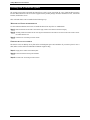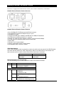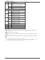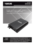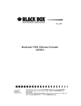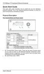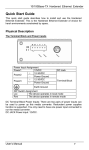
1
FEBRUARY, 2006
Ethernet Extender &
Media Converter Rack:
LB300A-RACK
CUSTOMER
SUPPORT
INFORMATION
Order toll-free in the U.S. 24 hours, 7 A.M. Monday to midnight Friday: 877-877-BBOX
FREE technical support, 24 hours a day, 7 days a week: Call 724-746-5500 or fax 724746-0746
Mail order: Black Box Corporation, 1000 Park Drive, Lawrence, PA 15055-1018
Web site: www.blackbox.com • E-mail: [email protected]
LB300A-RACK: 16-Bay Ethernet Extender and Media Converter Chassis
FEDERAL COMMUNICATIONS COMMISSION AND
CANADIAN DEPARTMENT OF COMMUNICATIONS
RADIO FREQUENCY INTERFERENCE STATEMENT
This equipment generates, uses and can radiate radio frequency energy and if not installed and used properly, that is,
in strict accordance with the manufacturer’s instructions, may cause interference to radio communication. It has been
tested and found to comply with the limits for a Class A computing device in accordance with the specifications in
Subpart B of Part 15 of FCC rules, which are designed to provide reasonable protection against such interference
when the equipment is operated in a commercial environment. Operation of this equipment in a residential area is
likely to cause interference, in which case the user at his own expense will be required to take whatever measures
may be necessary to correct the interference.
Changes or modifications not expressly approved by the party responsible for compliance could void the user’s
authority to operate the equipment.
This digital apparatus does not exceed the Class A limits for radio noise emission from digital apparatus set out in the
Radio Interference Regulation of the Canadian Department of Communications.
Le présent appareil numérique n’émet pas de bruits radioélectriques dépassant les limites applicables aux appareils
numériques de la classe A prescrites dans le Règlement sur le brouillage radioélectrique publié par le ministère des
Communications du Canada.
Normas Oficiales Mexicanas (NOM)
INSTRUCCIONES DE SEGURIDAD
1. Todas las instrucciones de seguridad y operación deberán ser leídas antes de que el aparato eléctrico sea
operado.
2. Las instrucciones de seguridad y operación deberán ser guardadas para referencia futura.
3. Todas las advertencias en el aparato eléctrico y en sus instrucciones de operación deben ser respetadas.
4. Todas las instrucciones de operación y uso deben ser seguidas.
5. El aparato eléctrico no deberá ser usado cerca del agua—por ejemplo, cerca de la tina de baño, lavabo,
sótano mojado o cerca de una alberca, etc.
6. El aparato eléctrico debe ser usado únicamente con carritos o pedestales que sean recomendados por el
fabricante.
7. El aparato eléctrico debe ser montado a la pared o al techo sólo como sea recomendado por el fabricante.
8. Servicio—El usuario no debe intentar dar servicio al equipo eléctrico más allá a lo descrito en las instrucciones
de operación. Todo otro servicio deberá ser referido a personal de servicio calificado.
9. El aparato eléctrico debe ser situado de tal manera que su posición no interfiera su uso. La colocación del
aparato eléctrico sobre una cama, sofá, alfombra o superficie similar puede bloquea la ventilación, no se debe
colocar en libreros o gabinetes que impidan el flujo de aire por los orificios de ventilación.
10. El equipo eléctrico deber ser situado fuera del alcance de fuentes de calor como radiadores, registros de calor,
estufas u otros aparatos (incluyendo amplificadores) que producen calor.
11. El aparato eléctrico deberá ser connectado a una fuente de poder sólo del tipo descrito en el instructivo de
operación, o como se indique en el aparato.
12. Precaución debe ser tomada de tal manera que la tierra fisica y la polarización del equipo no sea eliminada.
13. Los cables de la fuente de poder deben ser guiados de tal manera que no sean pisados ni pellizcados por
objetos colocados sobre o contra ellos, poniendo particular atención a los contactos y receptáculos donde
salen del aparato.
14. El equipo eléctrico debe ser limpiado únicamente de acuerdo a las recomendaciones del fabricante.
15. En caso de existir, una antena externa deberá ser localizada lejos de las lineas de energia.
2
16. El cable de corriente deberá ser desconectado del cuando el equipo no sea usado por un largo periodo de
tiempo.
17. Cuidado debe ser tomado de tal manera que objectos liquidos no sean derramados sobre la cubierta u
orificios de ventilación.
18. Servicio por personal calificado deberá ser provisto cuando:
A: El cable de poder o el contacto ha sido dañado; u
B: Objectos han caído o líquido ha sido derramado dentro del aparato; o
C: El aparato ha sido expuesto a la lluvia; o
D: El aparato parece no operar normalmente o muestra un cambio en su desempeño; o
E: El aparato ha sido tirado o su cubierta ha sido dañada.
3
LB300A-RACK: 16-Bay Ethernet Extender and Media Converter Chassis
Preface
This manual describes how to install and use LB300A-RACK, the 16-Bay Ethernet Extender and Media Converter
Chassis. The system introduced here is capable of housing up to sixteen media converters, each of which offers one
channel media conversion solution:
10/100BaseTX ↔ 100BaseFX
100BaseTX
↔ 100BaseFX
100BaseFX
↔ 100BaseFX
(multi-mode, single-mode ↔ single-mode)
1000BaseT
↔ 1000BaseSX/LX
1000BaseSX
↔ 1000BaseLX
(multi-mode, single-mode ↔ single-mode)
10/100BaseTX ↔ 100BaseFX (WDM, single-mode)
100BaseTX
↔ 100BaseFX (WDM, single-mode)
100BaseFX
↔ 100BaseFX
(WDM, single-mode ↔ WDM, single-mode)
10/100BaseTX ↔ VDSL
In this manual, you will find:
•
•
•
•
•
Introduction on the Chassis System
Product features
Illustrative LEDs functions
Installation instructions
Specifications
4
Table of Contents
PREFACE
4
TABLE OF CONTENTS 5
PRODUCT OVERVIEW 6
LB300A-RACK: 16-BAY MEDIA CONVERTER CHASSIS ................................................................................. 6
PACKAGE CONTENTS ................................................................................................................................... 6
PRODUCT FEATURES ................................................................................................................................... 7
FRONT PANEL DISPLAY ................................................................................................................................ 8
Front Panel............................................................................................................................................................................................................. 8
Understanding LEDs .............................................................................................................................................................................................. 8
INSTALLATION
9
SELECTING A SITE FOR THE EQUIPMENT ....................................................................................................... 9
DECIDING HOW TO INSTALL THE SYSTEM .................................................................................................... 10
Mounted to 19-inch standard rack ........................................................................................................................................................................ 10
Desktop or any flat surface ................................................................................................................................................................................... 10
INSTALLING ETHERNET EXTENDER: LB300A ........................................................................................ 11
CONNECTING TO POWER ............................................................................................................................ 13
Power supply........................................................................................................................................................................................................ 13
Connecting to power............................................................................................................................................................................................. 13
COOLING SYSTEM ...................................................................................................................................... 14
SPECIFICATIONS
15
Chassis System.................................................................................................................................................................................................... 15
Power Supply ....................................................................................................................................................................................................... 15
5
LB300A-RACK: 16-Bay Ethernet Extender and Media Converter Chassis
Product Overview
LB300A-RACK: 16-Bay Media Converter Chassis
Figure 1: LB300A-RACK: Chassis equipped with one power supply
Package Contents
When you unpack the product package, you shall find these items listed below.
3
3
3
3
3
3
LB300A-RACK:16-Bay Media Converter Chassis
One power supply installed on the chassis
AC power cord
User’s Manual
Accessories: rack mount screws, brackets, & bracket screws
Media converter carriers, fitted to each bay
Please inspect the contents, and report any apparent damage or missing items immediately to your authorized
reseller.
6
LB300A-RACK: Product Features
♦
♦
♦
♦
♦
HOUSE UP TO SIXTEEN MEDIA CONVERTERS
FRONT PANEL LEDS FOR POWER STATUS
STANDARD 19” RACKMOUNTABLE SIZE, 2U
NON-STOP OPERATION & MINIMAL DOWNTIME
HOT-SWAPPABLE
The following items are designed to be hot swappable to allow easy and quick replacement:
- Media converters
- Power supplies with fans
♦
ADEQUATE VENTILATION
- Provides one cooling fan on the left and right side
- Ventilation holes on each side
♦
POWER REDUNDANCY & POWER ISOLATION
Two high quality internal power supplies provided for load-sharing purpose.
- Load sharing mechanism: If one power supply should fail, the
redundant power supply is capable of taking over immediately
- Converter bay power isolation ensures each bay is electrically
isolated from each other
♦
OVER CURRENT PROTECTION
- Fuses on PCB for each converter bay
- Fuse on each power supply
7
LB300A-RACK: 16-Bay Ethernet Extender and Media Converter Chassis
Front Panel Display
FRONT PANEL
The front panel of this 16-Bay Media Converter Chassis shows it is capable of housing up to sixteen media
converters in bay 1~16.
There is an array of LED indicators, which provides you with instant feedback on the status of each power.
Figure 2: Front Panel of LB300A-RACK: the 16-Bay Media Converter Chassis
UNDERSTANDING LEDS
Power
Supply’s
Switch LED
Green
Power switched on
Off
Power switched off
Blown fuse
Power supply failed
L
Before you use this table for troubleshooting, make sure the chassis system is properly connected to power and switched on.
8
Installation
Selecting a Site for the Equipment
As with any electric device, you should place the equipment where it will not be subjected to extreme temperatures,
humidity, or electromagnetic interference. Specifically, the site you select should meet the following requirements:
-
The ambient temperature should be between 32 and 104 degrees Fahrenheit (0 to 40 degrees Celsius).
-
The relative humidity should be less than 90 percent, non-condensing.
-
Surrounding electrical devices should not exceed the electromagnetic field (RFC) standards for IEC 801-3,
Level 2 (3V/M) field strength.
-
Make sure that the equipment receives adequate ventilation. Do not block the ventilation holes on each side of
the switch or the fan exhaust port on the side or rear of the equipment.
-
The power outlet should be within 1.8 meters of the switch.
9
16-Bay Media Converter Chassis
Deciding How to Install the System
We strongly suggest that you install the chassis first, as this is more convenient for you to install media converters
into the chassis with ease. The accessories supplied in the product package includes: rackmount screws, rackmount
brackets, and bracket screws.
This well-built chassis can be installed in the following ways:
MOUNTED TO 19-INCH STANDARD RACK
Use the rackmount brackets and screws to install the chassis into any EIA 19” standard rack.
Step 1: Attach the brackets to each side of the chassis. Apply screws to each side and secure them tightly.
Step 2:
Carefully position the chassis into the rack. Align the brackets to the side holes on the rack and use rack screws to secure
the chassis with the rack.
Step 3:
Proceed to the “Connecting to Power” section.
DESKTOP OR ANY FLAT SURFACE
The chassis can sit on desktop or any flat surface with adequate space and ventilation. If you want to place it onto a
shelf, make sure the shelf can withstand a minimum weight of 10kg.
Step 1:
Simply put the chassis on the desired place.
Step 2:
Ensure the chassis receives good ventilation.
Step 3:
Proceed to the “Connecting to Power” section.
10
User’s Manual
Installing ETHERNET EXTENDER: LB300A
The chassis is equipped with media converter carriers, each of which is fitted into bays of the chassis.
LB300A: Ethernet Extender Product Overview
LB300A: Ethernet Extender Product Features
y One 10/100BaseTX (TX) Ethernet port with RJ-45 connector
y Auto negotiation of speed and duplex mode on TX port
y Auto MDIX on TX port
y Complies with IEEE 802.3 10BaseT and IEEE 802.3u 100BaseTX standards
y One Ethernet over VDSL port with RJ-11 connector
y Ethernet over VDSL port auto senses the speed of 1/3/5/10/15/20/25/30Mbps
y One DIP switch for configuring VDSL local or remote mode
y Status LEDs
y External AC to DC power adapter
y Used as a stand-alone device or with a chassis
y Hot-swappable when used with a chassis
VDSL Mode Settings
VDSL mode settings are made very simple by means of a switch at the rear panel of the VDSL Extender.
The switch has two positions for VDSL mode settings. Refer to the table below for more details. One
device must be set to Loc and the other to Rmt when two devices are connected.
Loc
The device operates in
local mode
Rmt
The device operates in
remote mode
Ethernet Extender Front Panel & LEDs
The LED indicators give you instant feedback on status of the Ethernet Extender:
LEDs
Pwr
State
Steady
Off
Ethernet
Lnk/Act Steady
Flashing
Off
Indication
Power on
Pwr stands for POWER
Power off
A valid Ethernet connection
established
Lnk stands for LINK
Transmitting or receiving Ethernet
data
Act stands for ACTIVITY
Neither valid Ethernet connection
established nor transmitting/receiving
11
16-Bay Media Converter Chassis
Fdx
Steady
Flashing
Off
Ethernet data
Ethernet Connection in full duplex
mode
Fdx stands for FULL-DUPLEX
Collision occurred
Ethernet Connection in half-duplex
mode
Ethernet over VDSL
1
Green
The VDSL port transmitting/receiving
at 1Mbps, up to 1900M
Amber
The VDSL port transmitting/receiving
at 3Mbps, up to 1700M
2
Green
The VDSL port transmitting/receiving
at 5Mbps, up to 1600M
Amber
The VDSL port transmitting/receiving
at 10Mbps, up to 1500M
3
Green
The VDSL port transmitting/receiving
at 15Mbps, up to 1400M
Amber
The VDSL port transmitting/receiving
at 20Mbps, up to 1000M
4
Green
The VDSL port transmitting/receiving
at 25Mbps, up to 800M
Amber
The VDSL port transmitting/receiving
at 30Mbps, up to 600M
Rmt
Steady
The device operates in remote mode
Loc
Steady
The device operates in local mode
Err
Steady
Error occurred
Lnk
Steady
A valid VDSL connection established
Step 1: To install a media converter onto any of the carriers, you have to unscrew the carrier from the desired bay first.
Step 2:
Fit the media converter onto the carrier.
Step 3:
When the media converter is completely seated onto the carrier, insert the carrier to the guide rails of the bay slot.
Step 4:
Carefully slide in the carrier until it is fully and firmly fitted to the power socket. Fasten the screws on the carrier.
L
i.
ii.
iii.
12
The chassis is designed to house only the proprietary media converters.
Never insert any media converter into the chassis directly without using the supplied carriers. These carriers allow secure and
consistent placement of the media converters into the chassis’ backplane without causing any damage.
For details, please refer to the User’s Manual for media converters.
User’s Manual
Connecting to Power
POWER SUPPLY
The chassis ships with two power supplies. When the chassis is equipped with two power supplies, you can have the
following advanced performance.
♦
Hot Swappable –
The design of the power system is based on an idea of providing maximum flexibility and redundancy. In this way,
you may remove any of the two power supplies without turning off the system.
♦
Redundancy –
During operation, both power supplies are switched on and share the current load. In case that one of them
should fail, the other will instantaneously take 100% of the load without any loss. Similarly, if one power supply is
removed from servicing, it can be switched off and removed while the chassis continues functioning.
♦
Protection System –
The power of each converter bay comes from the two shared power supplies. Each bay is isolated from each
other under a certain protection mechanism, so that it is free from any problem that might occur to the power
supplies or faulty converter bay. This is the best solution to protect your investment in media converters.
CONNECTING TO POWER
The chassis system is equipped with one power supply.
Step 1: Connect the supplied AC power cord to the receptacle on the front panel of each power supply.
Step 2: Attach the plug into a standard AC outlet with a voltage range from 100~240Vac.
Step 3:
Turn on the chassis system by flipping the ON/OFF switch beside the receptacle to ON position. The LEDs on the front
panel of the media converter chassis system will come on then.
Figure 3: The rear of the 16-Bay Media Converter Chassis when equipped with redundant power supply
13
16-Bay Media Converter Chassis
Cooling System
The chassis system can hold two power supplies and up to sixteen media converters, and therefore, it is necessary to
provide a good cooling system and so to achieve obtain adequate ventilation.
The chassis can equip with one or two hot-swappable power supplies with fans at the rear. The chassis is also
equipped with one fan on the left and right side of the chassis.
Figure 4: The rear side of the 16-Bay Media Converter Chassis
14
User’s Manual
Specifications
CHASSIS SYSTEM
Capacity
Power
Cooling
LED Indicators
Dimensions
Net Weight
Sixteen bays for housing up to sixteen
media converters
One power supplies provided, when
equipped with dual power supply, one of
redundant power supply can be hotswappable
two power supplies with fans
One fan on the left and right side of the
chassis
2 LEDs (1 LED for each power supply’s
power status)
W440 mm × D276 mm × H90 mm
Standard 19” size, 2 U
8.5kg approx. (Fully fitted with sixteen media
converters)
POWER SUPPLY
Power Input
Power Output
Load
Operating
Temperature
Storage
Temperature
Emissions
User’s Manual
110~240Vac, 50~60Hz
12Vdc, 84W (x2) max.
7A (x2) max.
0°C to 40° C (32°F to 104°F)
-25°C to 70°C (-13°F to 158°F)
CE Class A, FCC part 15 Class A
15