1
LFD DISPLAY User Manual QM85D The color and the appearance may differ depending on the product, and the specifications are subject to change without prior notice to improve the performance. Recommended hours of use per day of this product is under 16 hours. If the product is used for longer than 16 hours a day, the warranty may be void. Table of contents Before Using the Product Copyright5 Safety Precautions 6 Symbols6 Cleaning6 Storage7 Electricity and Safety 7 Installation8 Operation10 Precautions when handling the panel 13 Preparations Checking the Components 14 Components14 Items sold separately 15 Parts16 Control Panel 16 Reverse Side 18 Anti-theft Lock 19 Remote Control 20 Connection Using an IR Stereo Cable (sold separately) 22 Before Installing the Product (Installation Guide) 23 Tilting Angle and Rotation 23 Ventilation23 Dimensions24 Installing the Wall Mount Installing the Wall Mount Wall Mount Kit Specifications (VESA) 25 25 25 Remote Control (RS232C) 26 Cable Connection 26 Connection29 Control Codes 30 Connecting and Using a Source Device Changing the Input source 48 Source48 Using MDC MDC Program Installation/Uninstallation 49 Installation49 Uninstallation49 Connecting to MDC Using MDC via RS-232C (serial data communications standards) Using MDC via Ethernet 50 50 51 Before Connecting Pre-connection Checkpoints 39 39 Connecting to a PC Connection using the D-SUB cable (Analog type) Connection using a DVI cable (Digital type) Connection Using an HDMI-DVI Cable Connection Using an HDMI Cable Connection Using an DP Cable 39 39 40 40 41 41 Connecting to a Video Device Connection Using an HDMI-DVI Cable Connection Using an HDMI Cable 42 42 43 On/Off Timer55 On Timer55 Off Timer55 Holiday Management56 Connecting to an Audio System 43 Network Settings57 Connecting the LAN Cable 44 MagicInfo Player I58 Attaching the Network box (Sold separately)45 ID Settings59 Device ID59 PC Connection Cable59 Connecting the Network box (Sold separately)46 MagicInfo46 Home feature Multi Screen53 Picture Mode54 2 Table of contents Video Wall60 Video Wall60 Horizontal x Vertical60 Screen Position61 Format61 Auto Adjustment72 PC Screen Adjustment72 Picture Off73 Picture Mode63 Backlight / Brightness / Contrast / Sharpness / Color / Tint (G/R)64 Color Temperature65 White Balance65 Gamma66 Calibrated Value66 Picture Options67 Color Tone68 Digital NR68 HDMI Black Level68 Film Mode68 Auto Motion Plus69 Dynamic Backlight69 Picture Size70 Picture Size70 Zoom/Position71 Resolution71 Setup83 Initial settings (System)83 OnScreen Display Time84 Clock Set84 DST84 Sleep Timer84 Power On Delay84 Multi Screen74 Multi Screen74 PIP75 Triple Screen77 Four Screen77 Auto Source Switching85 Auto Source Switching85 Primary Source Recovery85 Primary Source85 Secondary Source85 Rotation78 Rotate Menu78 Rotate Content78 Aspect Ratio78 Power Control86 Auto Power On86 PC Module Power86 Standby Control87 Network Standby87 Power Button87 Reset Picture73 More settings62 Screen Adjustment System Screen Protection79 Pixel Shift79 Timer80 Immediate Display81 Side Gray81 Message Display81 Source Info81 No Signal Message81 MDC Message81 Eco Solution88 Energy Saving88 Eco Sensor88 Screen Lamp Schedule88 No Signal Power Off 89 Auto Power Off89 Temperature Control89 Menu Language82 Change PIN90 Reset OnScreen Display82 General91 3 Table of contents Security91 HDMI Hot Plug91 Reset System92 Sound Adjustment HDMI Sound93 Troubleshooting Guide Appendix Requirements Before Contacting Samsung Customer Service Center 100 Testing the Product 100 Checking the Resolution and Frequency 100 Check the followings. 101 Responsibility for the Pay Service (Cost to Customers) 116 Not a product defect 116 A Product damage caused by customer's fault 116 Others116 Q & A WEEE117 Correct Disposal of This Product (Waste Electrical & Electronic Equipment) 117 Correct disposal of batteries in this product 117 108 Sound on Video Call94 Speaker Selection94 Specifications Reset Sound95 General110 Support Software Update96 PowerSaver112 Optimum Picture Quality and Afterimage Burn-in Prevention Optimum Picture Quality Prevention of Afterimage Burn-in Preset Timing Modes License120 113 118 118 118 Terminology121 Contact Samsung96 Go to Home97 Multi Screen97 Picture Mode97 On/Off Timer97 Network Settings97 MagicInfo Player I97 ID Settings98 Video Wall98 More settings98 Reset All99 4 Chapter 01 Before Using the Product Copyright The contents of this manual are subject to change without notice to improve quality. © 2014 Samsung Electronics Samsung Electronics owns the copyright for this manual. Use or reproduction of this manual in parts or entirety without the authorization of Samsung Electronics is prohibited. Microsoft, Windows are registered trademarks of Microsoft Corporation. VESA, DPM and DDC are registered trademarks of the Video Electronics Standards Association. Ownership of all other trademarks is attributed to their due owner. •• An administration fee may be charged if either -- (a) an engineer is called out at your request and there is no defect in the product (i.e. where you have failed to read this user manual). -- (b) you bring the unit to a repair Center and there is no defect in the product (i.e. where you have failed to read this user manual). •• The amount of such administration charge will be advised to you before any work or home visit is carried out. 5 Safety Precautions Cleaning ――Exercise care when cleaning as the panel and exterior of advanced LCDs are easily scratched. Caution ――Take the following steps when cleaning. ――The following images are for reference only. Real-life situations may differ from what is shown in the images. RISK OF ELECTRIC SHOCK DO NOT OPEN Caution : TO REDUCE THE RISK OF ELECTRIC SHOCK, DO NOT REMOVE COVER. (OR BACK) THERE ARE NO USER SERVICEABLE PARTS INSIDE. REFER ALL SERVICING TO QUALIFIED PERSONNEL. 1 Power off the product and computer. 2 Disconnect the power cord from the product. ――Hold the power cable by the plug and do not touch the cable with wet hands. Otherwise, an electric shock may result. This symbol indicates that high voltage is present inside. 3 It is dangerous to make any kind of contact with any internal part of this product. Wipe the product with a clean, soft and dry cloth. •• Do not use detergents that contain alcohol, solvent or surface-active agents. This symbol alerts you that important literature concerning operation and maintenance has been included with this product. ! •• Do not spray water or detergent directly on the product. Symbols Warning A serious or fatal injury may result if instructions are not followed. 4 Wet a soft and dry cloth in water and wring thoroughly to clean the exterior of the product. Caution Personal injury or damage to properties may result if instructions are not followed. Activities marked by this symbol are prohibited. 5 Connect the power cord to the product when cleaning is finished. 6 Power on the product and computer. Instructions marked by this symbol must be followed. 6 Storage Connect the power plug to a grounded power socket (type 1 insulated devices only). Due to the characteristics of high-glossy products, using a UV humidifier nearby may create white-coloured stains on the product. ――Contact Customer Service Centre if the inside of the product needs cleaning (service fee will be •• An electric shock or injury may result. ! Do not bend or pull the power cord with force. Be careful not to leave the power cord under a heavy object. charged). Electricity and Safety •• Damage to the cord may result in a fire or electric shock. ――The following images are for reference only. Real-life situations may differ from what is shown in the images. Do not place the power cord or product near heat sources. •• A fire or electric shock may result. Warning Do not use a damaged power cord or plug, or a loose power socket. •• An electric shock or fire may result. Clean any dust around the pins of the power plug or the power socket with a dry cloth. •• A fire may result. Do not use multiple products with a single power socket. •• Overheated power sockets may cause a fire. ! Do not touch the power plug with wet hands. Otherwise, an electric shock may result. Insert the power plug all the way in so it is not loose. •• An unsecure connection may cause a fire. ! 7 Installation Caution Do not disconnect the power cord while the product is being used. •• The product may become damaged by an electric shock. Warning DO NOT PLACE CANDLES, INSECT REPELLANTS OR CIGARETTES ON TOP OF THE PRODUCT. DO NOT INSTALL THE PRODUCT NEAR HEAT SOURCES. •• A fire may result. Only use the power cord provided with your product by Samsung. Do not use the power cord with other products. •• A fire or electric shock may result. Have a technician install the wall-mount hanger. ! •• Installation by an unqualified person can result in an injury. •• Only use approved cabinets. Keep the power socket where the power cord is connected unobstructed. •• The power cord must be disconnected to cut off power to the product when an issue occurs. ! ! Do not install the product in poorly ventilated spaces such as a bookcase or closet. •• Note that the product is not completely powered down by using only the power button on the remote. •• An increased internal temperature may cause a fire. Hold the plug when disconnecting the power cord from the power socket. •• An electric shock or fire may result. Install the product at least 10 cm away from the wall to allow ventilation. •• An increased internal temperature may cause a fire. ! ! Keep the plastic packaging out of the reach of children. •• Children may suffocate. ! 8 Do not install the product on an unstable or vibrating surface (insecure shelf, sloped surface, etc.) Caution •• The product may fall and become damaged and/or cause an injury. Do not drop the product while moving. •• Using the product in an area with excess vibration may damage the product or cause a fire. Do not install the product in a vehicle or a place exposed to dust, moisture (water drips, etc.), oil, or smoke. •• Product failure or personal injury may result. ! Do not set down the product on its front. •• A fire or electric shock may result. •• The screen may become damaged. ! Do not expose the product to direct sunlight, heat, or a hot object such as a stove. When installing the product on a cabinet or shelf, make sure that the bottom edge of the front of the product is not protruding. •• The product lifespan may be reduced or a fire may result. •• The product may fall and become damaged and/or cause an injury. •• Install the product only on cabinets or shelves of the right size. Do not install the product within the reach of young children. •• The product may fall and injure children. Set down the product gently. •• As the front is heavy, install the product on a flat and stable surface. Edible oil, such as soybean oil, can damage or deform the product. Do not install the product in a kitchen or near a kitchen counter. •• Product failure or personal injury may result. ! SAMSUNG ! Installing the product in an unusual place (a place exposed to a lot of fine dust, chemical substances, extreme temperatures or a significant presence of moisture, or a place where the product will operate continuously for an extended period of time) may seriously affect its performance. •• Be sure to consult Samsung Customer Service Centre if you want to install the product at such a place. 9 Operation Do not leave heavy objects or items that children like (toys, sweets, etc.) on top of the product. •• The product or heavy objects may fall as children try to reach for the toys or sweets resulting in a serious injury. Warning There is a high voltage inside the product. Never disassemble, repair or modify the product yourself. During a lightning or thunderstorm, power off the product and remove the power cable. •• A fire or electric shock may result. •• A fire or electric shock may result. •• Contact Samsung Customer Service Centre for repairs. ! To move the product, first disconnect all the cables from it, including the power cable. Do not drop objects on the product or apply impact. •• A fire or electric shock may result. •• Otherwise, the power cord may be damaged and a fire or electric shock may result. ! ! If the product generates abnormal sounds, a burning smell or smoke, disconnect the power cord immediately and contact Samsung Customer Service Centre. Do not move the product by pulling the power cord or any cable. •• Product failure, an electric shock or fire may result from a damaged cable. •• An electric shock or fire may result. ! Do not let children hang from the product or climb on top of it. If a gas leakage is found, do not touch the product or power plug. Also, ventilate the area immediately. •• Children may become injured or seriously harmed. •• Sparks can cause an explosion or fire. ! If the product is dropped or the outer case is damaged, turn off the power switch and disconnect the power cord. Then contact Samsung Customer Service Centre. •• Continued use can result in a fire or electric shock. GAS Do not lift or move the product by pulling the power cord or any cable. •• Product failure, an electric shock or fire may result from a damaged cable. 10 Do not use or keep combustible spray or an inflammable substance near the product. Caution •• An explosion or fire may result. Leaving the screen fixed on a stationary image for an extended period of time may cause afterimage burn-in or defective pixels. ! Ensure the vents are not blocked by tablecloths or curtains. •• Activate power-saving mode or a moving-picture screen saver if you will not be using the product for an extended period of time. ! •• An increased internal temperature may cause a fire. -_100 Do not insert metallic objects (chopsticks, coins, hairpins, etc) or objects that burn easily (paper, matches, etc) into the product (via the vent or input/ output ports, etc). •• Dust accumulation combined with heat can cause a fire, electric shock or electric leakage. ! Use the product at the recommended resolution and frequency. •• Be sure to power off the product and disconnect the power cord when water or other foreign substances have entered the product. Then contact Samsung Customer Service Centre. •• Product failure, an electric shock or fire may result. Disconnect the power cord from the power socket if you do not plan on using the product for an extended period of time (vacation, etc). •• Your eyesight may deteriorate. ! Do not hold the product upside-down or move it by holding the stand. Do not place objects containing liquid (vases, pots, bottles, etc) or metallic objects on top of the product. •• The product may fall and become damaged or cause an injury. •• Be sure to power off the product and disconnect the power cord when water or other foreign substances have entered the product. Then contact Samsung Customer Service Centre. •• Product failure, an electric shock or fire may result. Looking at the screen too close for an extended period of time can deteriorate your eyesight. ! Do not use humidifiers or stoves around the product. •• A fire or electric shock may result. 11 Rest your eyes for more than 5 minutes for every 1 hour of product use. Be careful that children do not place the battery in their mouths when removed from the remote control. Place the battery in a location that children or infants cannot reach. •• Eye fatigue will be relieved. •• If children have had the battery in their mouths, consult your doctor immediately. ! Do not touch the screen when the product has been turned on for an extended period of time as it will become hot. When replacing the battery, insert it with the right polarity (+, -). Store small accessories out of the reach of children. Use only the specified standardized batteries, and do not use a new battery and a used battery at the same time. •• Otherwise, the battery may become damaged or it may cause fire, personal injury or damage due to leakage of the internal liquid. •• Otherwise, the batteries may be damaged or cause fire, personal injury or damage due to a leakage of the internal liquid. ! ! Exercise caution when adjusting the product angle or stand height. The batteries (and rechargeable batteries) are not ordinary refuse and must be returned for recycling purposes. The customer is responsible for returning the used or rechargeable batteries for recycling. •• Your hand or finger may get stuck and injured. ! •• Tilting the product at an excessive angle may cause the product to fall and an injury may result. Do not place heavy objects on the product. ! •• The customer can return used or rechargeable batteries to a nearby public recycling centre or to a store selling the same type of the battery or rechargeable battery. •• Product failure or personal injury may result. When using headphones or earphones, do not turn the volume too high. •• Having the sound too loud may damage your hearing. 12 Precautions when handling the panel Do not stand the product as shown in the image. The panel is fragile and can get damaged. Lay the product down to handle it as shown in the image. (the packaging can be used). ! Ensure you use the handles on the back when moving the product. ! Do not hold or grasp any area of the product within 15 mm from the front. 15 mm 13 Chapter 02 Preparations Checking the Components -- The appearance of the components and items sold separately may differ from the image shown. Components ――Components may differ in different locations. Warranty card Quick setup guide (Not available in some locations) Regulatory guide Power cord - + - -- Contact the vendor where you purchased the product if any components are missing. + Batteries (Not available in some locations) Remote Control DP cable 14 Items sold separately -- The following items can be purchased at your nearest retailer. DP-DVI cable Wall-mount Kit RS232C-Stereo cable DVI cable HDMI-DVI cable (Used to connect a network box) HDMI cable D-SUB cable RS232C(IN) adapter RS232C(OUT) adapter Stereo cable RCA stereo cable LAN cable External ambient sensor Network Box -- The RS232C adapter can be used to connect to another monitor using the D-SUB (9-pin) type RS232C cable. -- Ensure you connect each of the adapters to the correct RS232C IN or OUT port on the product. 15 ――The color and shape of parts may differ from what is shown. Specifications are subject to change without notice to improve Parts quality. Panel Key Control Panel Buttons Description Power on the product. If you press the button when the product is turned on, the control menu will be displayed. ――To exit the OSD menu, press and hold the panel key for at least one second. Move to the upper or lower menu. You can also adjust the value of an option. Speaker Move to the left or right menu. ――You can adjust the volume by moving the panel key left or right when the control menu is not displayed. Panel Key Remote sensor Press a button on the remote control pointing at the sensor on the front of the product to perform the corresponding function. ――Using other display devices in the same space as the remote control of this product can cause the other display devices to be inadvertently controlled. Use the remote control within 7 m to 10 m from the sensor on the product at an angle of 30 from the left and right. ――Store used batteries out of reach of children and recycle. ――Do not use a new and used battery together. Replace both batteries at the same time. Remote sensor ――Remove batteries when the remote control is not to be used for an extended period of time. 16 ――If you press the button on the panel key when the product is turned on, the control menu will be displayed. Buttons Description Select the connected input source. Control menu Source Move the panel key right to select Source in the control menu. When the list of input sources is displayed, move the panel key left or right to select the desired input source. Next, press the panel key. Display the OSD menu. Menu Home Move the panel key left to select Menu in the control menu. The OSD control screen will appear. Move the panel key right to select the desired menu. You can select a sub-menu item by moving the panel key up, down, left, or right. To change settings, select the desired menu and press the panel key. Enter Go to Home mode. Move the panel key up to select Home in the control menu. Power off the product. Power Off Move the panel key down to select Power Off the panel key. Return Exit the control menu. in the control menu. Next, press Return 17 Reverse Side Port ――The color and shape of parts may differ from what is shown. Specifications are IR /AMBIENT SENSOR IN Supplies power to the external sensor board or receives the light sensor signal. HDMI IN 1, HDMI IN 2, HDMI IN 3 Connects to a source device using a HDMI cable or HDMI-DVI cable. DP IN 3 (UHD 30Hz) Connects to a PC using a DP cable. subject to change without notice to improve quality. Description ――Obtain sharp picture quality when viewing UHD content at 30Hz. IR /AMBIENT SENSOR IN ――The recommended resolution for the DP IN 3 (UHD 30Hz) port is 1920 x 1080 @ 60 Hz. The resolution can be changed to the optimal resolution of 3840 x 2160 @ 30 Hz, if required. HDMI IN 3 DP IN 2 (UHD 60Hz) HDMI IN 2 DP IN 1 (UHD 60Hz) DVI IN / MAGICINFO IN HDMI IN 1 Connects to a PC using a DP cable. ――Obtain sharp picture quality when viewing UHD content at 60Hz. DVI IN: Connects to a source device using a DVI cable or HDMI-DVI cable. MAGICINFO IN: To use MagicInfo, make sure to connect the DP-DVI cable. DP IN 3 (UHD 30Hz) DP IN 2 (UHD 60Hz) Connects to MDC using a LAN cable. IR OUT Receives the remote control signal via the external sensor board and outputs the signal via LOOP OUT. RS232C OUT Connects to MDC using an RS232C adapter. RS232C IN DP IN 1 (UHD 60Hz) DVI IN / MAGICINFO IN IR OUT USB RJ45 RJ45 RGB IN RS232C OUT RS232C IN AUDIO OUT RGB / DVI / HDMI / AUDIO IN USB Connects to a USB device when upgrading software. RGB IN Connects to a source device using a D-SUB cable. AUDIO OUT Connects to the audio of a source device. RGB / DVI / HDMI / AUDIO IN Receives sound from a PC via an audio cable. 18 Anti-theft Lock ――An anti-theft lock allows you to use the product securely even in public places. ――The locking device shape and locking method depend on the manufacturer. Refer to the user guide provided with your anti-theft locking device for details. To lock an anti-theft locking device: 1 Fix the cable of your anti-theft locking device to a heavy object such as a desk. 2 Put one end of the cable through the loop on the other end. 3 Insert the locking device into the anti-theft lock slot at the back of the product. 4 Lock the locking device. -- An anti-theft locking device can be purchased separately. -- Refer to the user guide provided with your anti-theft locking device for details. -- Anti-theft locking devices can be purchased at electronics retailers or online. 19 Remote Control ――Using other display devices in the same space as the remote control of this product can cause the other display devices to be inadvertently controlled. ――A button without a description in the image below is not supported on the product. POWER OFF Power on the product. .QZ ABC DEF GHI JKL MNO PRS TUV WXY DEL-/-- SYMBOL 1 4 7 Not Available. Display or hide the onscreen display menu, or return to the previous menu. 5 8 0 3 6 VOL MENU SOURCE HOME Number buttons Enter the password in the OSD menu. 9 CH LIST Not Available. -- Remote control button functions may differ for different products. Mute the sound. Unmuting the sound: Press MUTE again or press the volume control(+ VOL -) button. MUTE Adjust the volume. Change the input source. 2 Power off the product. CH MagicInfo Player I MagicInfo Player I Launch Button. Go to Home Launch Button. 20 Quickly select frequently used functions. TOOLS INFO Display information about the current input source. Move to the upper, lower, left or right menu, or adjust an option's setting. Confirm a menu selection. Return to the previous menu. It sets safe lock function. If multiple products are connected through the Video Wall feature, press the SET button and enter a product ID using the number buttons. Control the product using the remote control. Cancel a value that has been set using the SET button and control all connected products using the remote control. RETURN EXIT PC DVI HDMI DP A B C D UNSET LOCK Exit the current menu. Manually select a connected input source from PC, DVI, HDMI1, HDMI2, HDMI3 or DisplayPort1, DisplayPort2, DisplayPort3. IR control SET Not Available. -- Remote control button functions may differ for different products. To place batteries in the remote control 21 Connection Using an IR Stereo Cable (sold separately) 1 2 Make sure to connect the External ambient sensor while the product is powered off. Then, power on the product. Controlling more than one display product using your remote control IR OUT IR /AMBIENT SENSOR IN •• Connect the IR OUT port on the product to the IR /AMBIENT SENSOR IN port on the other display product using the dedicated stereo cable. •• A command sent from the remote control pointed at product received by both display products 1 and 2 . ――The appearance may differ depending on the product. 1 will be Controlling more than one display product using an External ambient sensor (sold separately) 1 •• A command sent from the remote control pointed at product 1 (to which the External ambient sensor is connected) will be received by both display products 1 and 2 . ――The appearance may differ depending on the product. IR /AMBIENT SENSOR IN IR OUT 2 IR /AMBIENT SENSOR IN POWER SOURCE 22 Before Installing the Product (Installation Guide) To prevent injury, this apparatus must be securely attached to the floor/wall in accordance with the installation instructions. •• Ensure that an authorized installation company installs the wall mount. •• Otherwise, it may fall and cause personal injury. •• Make sure to install the specified wall mount. Tilting Angle and Rotation ――Contact Samsung Customer Service Center for further details. •• To use the product vertically (portrait), turn it clockwise so that the LED is pointing down. Ventilation Installation on a Perpendicular Wall A Minimum 40 mm B Ambient temperature: Under 35 C A •• When installing the product on a perpendicular wall, allow at least 40 mm of space between the product and wall surface for ventilation and ensure that the ambient A temperature is kept below 35 C. B Figure 1.1 Side view 23 ―― Figure 1.3 Side view Installation on an Indented Wall ――Contact Samsung Customer Service Center for further details. B D D Plane view A Minimum 40 mm B Minimum 70 mm A C Minimum 50 mm D Minimum 50 mm E Ambient temperature: Under 35 C ――When installing the product on an indented wall, allow at least the space specified above between the product and wall for ventilation and ensure that the ambient temperature is kept below 35 C. C E Figure 1.2 Side view Dimensions Unit: mm (inches) Model name 5 1 QM85D 1 1903.4 (74.94) 1 2 1877.0 (73.90) 23 1058.0 (41.65) 34 1090.5 (42.93) 45 105.1 (4.14) ――All drawings are not necessarily to scale. Some dimensions are subject to change without prior notice. Refer to the dimensions prior to performing installation of your product. Not responsible for typographical or printed errors. 2 4 3 24 Installing the Wall Mount Installing the Wall Mount The wall mount kit (sold separately) allows you to mount the product on the wall. For detailed information on installing the wall mount, see the instructions provided with the wall mount. We recommend you contact a technician for assistance when installing the wall mount bracket. Samsung Electronics is not responsible for any damage to the product or injury to yourself or others if you elect to install the wall mount on your own. Wall Mount Kit Specifications (VESA) ――Install your wall mount on a solid wall perpendicular to the floor. Before attaching the wall mount to surfaces other than plaster board, please contact your nearest dealer for additional information. If you install the product on a slanted wall, it may fall and result in severe personal injury. •• Samsung wall mount kits contain a detailed installation manual and all parts necessary for assembly are provided. •• Do not use screws that are longer than the standard length or do not comply with the VESA standard screw specifications. Screws that are too long may cause damage to the inside of the product. •• For wall mounts that do not comply with the VESA standard screw specifications, the length of the screws may differ depending on the wall mount specifications. •• Do not fasten the screws too firmly. This may damage the product or cause the product to fall, leading to personal injury. Samsung is not liable for these kinds of accidents. •• Samsung is not liable for product damage or personal injury when a non-VESA or non-specified wall mount is used or the consumer fails to follow the product installation instructions. •• Always have two people mount the product on a wall. •• Standard dimensions for wall mount kits are shown in the table below. Unit: mm (inches) Model name QM85D VESA screw hole specs (A * B) in millimeters 600 × 400 (23.62 × 15.75) Standard Screw M8 / L 14~16 Quantity 4 ――Do not install your Wall Mount Kit while your product is turned on. It may result in personal injury due to electric shock. 25 Remote Control (RS232C) •• Pin assignment 1 2 3 4 5 Cable Connection RS232C Cable Interface RS232C (9 pins) Pin TxD (No.2), RxD (No.3), GND (No.5) Bit rate 9600 bps Data bits 8 bit Parity None Stop bit 1 bit Flow control None Maximum length 15 m (only shielded type) 6 7 8 9 Pin Signal 1 Detect data carrier 2 Received data 3 Transmitted data 4 Prepare data terminal 5 Signal ground 6 Prepare data set 7 Send request 8 Clear to send 9 Ring indicator 26 LAN Cable •• RS232C cable Connector: 9-Pin D-Sub to Stereo Cable 9 •• Pin assignment 3 2 1 5 1 2 3 4 5 6 7 8 -P2- 6 -P1- 1 -P1Female -P1- -P2- -P2- Rx 2 --------> 3 Tx STEREO Tx 3 <-------- 2 Rx PLUG Gnd 5 ---------- 5 Gnd (3.5ø) Pin No Standard Color Signal 1 White and orange TX+ 2 Orange TX- 3 White and green RX+ 4 Blue NC 5 White and blue NC 6 Green RX- 7 White and brown NC 8 Brown NC 27 Cross LAN cable (PC to PC) •• Connector : RJ45 Direct LAN cable (PC to HUB) HUB RJ45 P2 RJ45 P1 P2 Signal P1 P2 Signal TX+ 1 <--------> 3 RX+ P1 P1 P2 RJ45 MDC P2 Signal TX- 2 <--------> 6 RX- <--------> 1 TX+ RX+ 3 <--------> 1 TX+ 2 <--------> 2 TX- RX- 6 <--------> 2 TX- RX+ 3 <--------> 3 RX+ RX- 6 <--------> 6 RX- Signal P1 TX+ 1 TX- 28 Connection •• Connection 2 •• Connection 1 RJ45 IN RS232C OUT IN RS232C OUT IN RS232C OUT IN RS232C RJ45 OUT •• Connection 3 RJ45 RS232C OUT IN RS232C OUT IN RS232C OUT IN RS232C OUT 29 No. Control Codes Viewing control state (Get control command) Header Command 0xAA Command type ID Data length Command 0xAA Command type Command type 10 Video Wall On 0x84 0~1 11 Video Wall User Control 0x89 - E.g. Power On & ID=0 Data length Data 1 Value Checksum Command No. Value range •• All communications take place in hexadecimals. The checksum is calculated by adding up all values except the header. If a checksum adds up to be more than 2 digits as shown below (11+FF+01+01=112), the first digit is removed. 0 ID Command Checksum Controlling (Set control command) Header Command type Command Value range 1 Power control 0x11 0~1 2 Volume control 0x12 0~100 3 Input source control 0x14 - 4 Screen mode control 0x18 - 5 Screen size control 0x19 0~255 6 PIP on/off control 0x3C 0~1 7 Auto adjustment control (PC and BNC only) 0x3D 0 8 Video wall mode control 0x5C 0~1 9 Safety Lock 0x5D 0~1 Header Command 0xAA 0x11 Header Command 0xAA 0x11 ID ID Data length Data 1 1 "Power" Data length Data 1 1 1 Checksum 12 •• To control all devices connected by a serial cable simultaneously irrespective of IDs, set the ID as "0xFE" and transmit commands. Commands will be executed by each device but ACK will not respond. 30 Power control Volume control •• Function A product can be powered on and off using a PC. •• Function The volume of a product can be adjusted using a PC. •• Viewing power state (Get Power ON / OFF Status) •• Viewing volume state (Get Volume Status) Header Command 0xAA 0x11 ID Data length Checksum 0 •• Setting power ON/Off (Set Power ON / OFF) Header Command 0xAA 0x11 ID Header Command 0xAA 0x12 Data length Data 1 "Power" Checksum Header Command 0xAA 0x12 •• Ack 0: Power OFF Header Command 0xAA 0xFF •• Ack 0xAA 0xFF ID Data length Ack/Nak r-CMD Val1 3 'A' 0x11 "Power" Checksum 0xAA 0xFF ID ID Data length Data 1 "Volume" Checksum Data length Ack/Nak r-CMD Val1 3 'N' 0x11 "ERR" ID Data length Ack/Nak r-CMD Val1 3 'A' 0x12 "Volume" Checksum •• Nak •• Nak Command 0 "Volume": Volume value code to be set on a product. (0-100) "Power": Power code to be set on a product. Header Checksum "Volume": Volume value code to be set on a product. (0-100) 1: Power ON Command Data length •• Setting the volume (Set Volume) "Power": Power code to be set on a product. Header ID Checksum Header Command 0xAA 0xFF ID Data length Ack/Nak r-CMD Val1 3 'N' 0x12 "ERR" Checksum "ERR" : A code showing what error has occurred. "ERR" : A code showing what error has occurred. 31 Input source control 0x24 HDMI2_PC •• Function The input source of a product can be changed using a PC. 0x25 DisplayPort ――DVI_video, HDMI1_PC and HDMI2_PC cannot be used with the Set command. They only respond to •• Viewing input source state (Get Input Source Status) Header Command 0xAA 0x14 ID Data length "Get" commands. ――This model does not support HDMI1, HDMI1_PC, HDMI2 and HDMI2_PC ports. Checksum ――MagicInfo is only available with models that contain the MagicInfo function. 0 ――RF(TV), DTV are only available with models that include a TV. •• Setting the input source (Set Input Source) Header Command 0xAA 0x14 ID •• Ack Data length Data 1 "Input Source" Checksum Header Command 0xAA 0xFF ID Data length Ack/Nak r-CMD Val1 3 'A' 0x14 "Input Source" "Input Source": An input source code to be set on a product. 0x14 PC 0x18 DVI 0x0C Input source 0x08 Component 0x20 MagicInfo 0x1F DVI_video 0x30 RF(TV) 0x40 DTV 0x21 HDMI1 0x22 HDMI1_PC 0x23 HDMI2 Checksum "Input Source": An input source code to be set on a product. •• Nak Header Command 0xAA 0xFF ID Data length Ack/Nak r-CMD Val1 3 'N' 0x14 "ERR" Checksum "ERR" : A code showing what error has occurred. 32 Screen mode control •• Nak •• Function The screen mode of a product can be changed using a PC. Screen mode cannot be controlled when the Video Wall function is enabled. ――This control can only be used on models that include a TV. Command 0xAA 0x18 ID Data length 0xAA ID 0x18 16 : 9 0x04 Zoom 0x31 Wide Zoom 0x0B 4:3 Ack/Nak r-CMD Val1 3 'N' 0x18 "ERR" Checksum •• Viewing the screen size (Get Screen Size Status) Data length Data Checksum 1 "Screen Mode" Header Command 0xAA 0x19 ID Data length Checksum 0 •• Ack "Screen Mode": A code that sets the product status 0x01 0xFF Data length •• Function The screen size of a product can be changed using a PC. 0 Command 0xAA ID Screen size control Checksum •• Setting the picture size (Set Picture Size) Header Command "ERR": A code showing what error has occurred •• Viewing screen status (Get Screen Mode Status) Header Header Header Command 0xAA 0xFF ID Data length Ack/Nak r-CMD Val1 3 'A' 0x19 "Screen Size" Checksum "Screen Size": product screen size (range: 0 – 255, unit: inch) •• Nak Header Command 0xAA 0xFF •• Ack Header Command 0xAA 0xFF ID Data length Ack/Nak r-CMD Val1 3 'A' 0x18 "Screen Mode" Checksum ID Data length Ack/Nak r-CMD Val1 3 'N' 0x19 "ERR" Checksum "ERR": A code showing what error has occurred "Screen Mode": A code that sets the product status 33 PIP On/Off control Auto adjustment control (PC and BNC only) •• Function The PIP mode of a product can be turned on or off using a PC. •• Function Automatically adjust the PC system screen using a PC. ――Only available on models that have the PIP function. ――The mode cannot be controlled if Video Wall is set to On. •• Viewing auto adjustment state (Get Auto Adjustment Status) None ――This function is not available in MagicInfo. •• Setting auto adjustment (Set Auto Adjustment) •• Viewing PIP on/off state (Get the PIP ON / OFF Status) Header Command 0xAA 0x3C ID Data length Checksum Command 0xAA 0x3C Command 0xAA 0x3D ID Data length Data 1 "Auto Adjustment" 0 ID Checksum "Auto Adjustment" : 0x00 (at all times) •• Setting PIP on/off (Set the PIP ON / OFF) Header Header Data length Data 1 "PIP" •• Ack Checksum "PIP": A code used to turn the PIP mode of a product on or off Header Command 0xAA 0xFF ID Data length Ack/Nak r-CMD Val1 3 'A' 0x3D "Auto Adjustment" Data length Ack/Nak r-CMD Val1 3 'A' 0x3D "ERR" 1: PIP ON 0: PIP OFF Checksum •• Nak •• Ack Header Command 0xAA 0xFF ID Data length Ack/Nak r-CMD Val1 3 'A' 0x3C "PIP" Checksum Header Command 0xAA 0xFF ID Checksum "ERR": A code showing what error has occurred "PIP": A code used to turn the PIP mode of a product on or off •• Nak Header Command 0xAA 0xFF ID Data length Ack/Nak r-CMD Val1 3 'A' 0x3C "PIP" Checksum "ERR": A code showing what error has occurred 34 Video Wall Mode Control Safety Lock •• Function Video Wall mode can be activated on a product using a PC. •• Function PC can be used to turn the Safety Lock function on or off on a product. This control is only available on a product whose Video Wall is enabled. This control is available regardless of whether or not the power is turned on. •• Viewing video wall mode (Get Video Wall Mode) Header Command 0xAA 0x5C ID Data length •• Viewing the safety lock state (Get Safety Lock Status) Checksum 0 •• Setting the video wall (Set Video Wall Mode) Header Command 0xAA 0x5C ID Header Command 0xAA 0x5D ID Data length Checksum 0 •• Enabling or disabling safety lock (Set Safety Lock Enable / Disable) Data length Data Checksum 1 "Video Wall Mode" Header Command 0xAA 0x5D ID Data length Data 1 "Safety Lock" "Video Wall Mode": A code used to activate Video Wall mode on a product "Safety Lock": Safety lock code to be set on a product 1: Full 1: ON 0: Natural 0: OFF Checksum •• Ack •• Ack Header Command 0xAA 0xFF ID Data length Ack/Nak r-CMD Val1 3 'A' 0x5C "Video Wall Mode" Checksum Header Command 0xAA 0xFF ID Data length Ack/Nak r-CMD Val1 3 'A' 0x5D "Safety Lock" Checksum "Safety Lock": Safety lock code to be set on a product "Video Wall Mode": A code used to activate Video Wall mode on a product •• Nak •• Nak Header Command 0xAA 0xFF ID Data length Ack/Nak r-CMD Val1 3 'A' 0x5C "ERR" Header Command 0xAA 0xFF Checksum ID Data length Ack/Nak r-CMD Val1 3 'N' 0x5D "ERR" Checksum "ERR": A code showing what error has occurred "ERR": A code showing what error has occurred 35 Video Wall On •• Nak •• Function Turn Video Wall on or off on the product from your computer. Header Command 0xAA 0xFF ID Data length Ack/Nak r-CMD Val1 3 'N' 0x84 ERR Checksum •• Get Video Wall On/Off Status Header Command 0xAA 0x84 ID Data length "ERR": A code showing what error has occurred Checksum Video Wall User Control 0 •• Function Turn the Video Wall function on or off on the product from your computer. •• Set Video Wall On/Off Header Command 0xAA 0x84 ID Data length Data Checksum 1 V.Wall_On •• Get Video Wall Status •• V.Wall_On: Video Wall code to be assigned to the product 1: Video Wall ON •• Ack Command 0xAA 0xFF Command 0xAA 0x89 ID Data length Checksum 0 •• Set Video Wall 0: Video Wall OFF Header Header ID Data length Ack/Nak r-CMD Val1 3 'A' 0x84 V.Wall_ On Checksum Header Command 0xAA 0x89 ID Data length Val1 Val2 2 Wall_Div Wall_SNo Checksum Wall_Div: Video Wall Divider code assigned to the product V.Wall_On : Same as above 36 10x10 Video Wall Model 1 2 3 4 5 6 7 8 9 10 11 12 13 14 15 Off 0x00 0x00 0x00 0x00 0x00 0x00 0x00 0x00 0x00 0x00 0x00 0x00 0x00 0x00 0x00 1 0x11 0x12 0x13 0x14 0x15 0x16 0x17 0x18 0x19 0x1A 0x1B 0x1C 0x1D 0x1E 0x1F 2 0x21 0x22 0x23 0x24 0x25 0x26 0x27 0x28 0x29 0x2A 0x2B 0x2C 0x2D 0x2E 0x2F 3 0x31 0x32 0x33 0x34 0x35 0x36 0x37 0x38 0x39 0x3A 0x3B 0x3C 0x3D 0x3E 0x3F 4 0x41 0x42 0x43 0x44 0x45 0x46 0x47 0x48 0x49 0x4A 0x4B 0x4C 0x4D 0x4E 0x4F 5 0x51 0x52 0x53 0x54 0x55 0x56 0x57 0x58 0x59 0x5A 0x5B 0x5C 0x5D 0x5E 0x5F 6 0x61 0x62 0x63 0x64 0x65 0x66 0x67 0x68 0x69 0x6A 0x6B 0x6C 0x6D 0x6E 0x6F 7 0x71 0x72 0x73 0x74 0x75 0x76 0x77 0x78 0x79 0x7A 0x7B 0x7C 0x7D 0x7E N/A 8 0x81 0x82 0x83 0x84 0x85 0x86 0x87 0x88 0x89 0x8A 0x8B 0x8C N/A N/A N/A 9 0x91 0x92 0x93 0x94 0x95 0x96 0x97 0x98 0x99 0x9A 0x9B N/A N/A N/A N/A 10 0xA1 0xA2 0xA3 0xA4 0xA5 0xA6 0xA7 0xA8 0xA9 0xAA N/A N/A N/A N/A N/A 11 0xB1 0xB2 0xB3 0xB4 0xB5 0xB6 0xB7 0xB8 0xB9 N/A N/A N/A N/A N/A N/A 12 0xC1 0xC2 0xC3 0xC4 0xC5 0xC6 0xC7 0xC8 N/A N/A N/A N/A N/A N/A N/A 13 0xD1 0xD2 0xD3 0xD4 0xD5 0xD6 0xD7 N/A N/A N/A N/A N/A N/A N/A N/A 14 0xE1 0xE2 0xE3 0xE4 0xE5 0xE6 0xE7 N/A N/A N/A N/A N/A N/A N/A N/A 15 0xF1 0xF2 0xF3 0xF4 0xF5 0xF6 N/A N/A N/A N/A N/A N/A N/A N/A N/A 37 Wall_SNo: Product Number code assigned to the product 10x10 Video Wall Model : ( 1 ~ 100) Set Number Data 1 0x01 2 0x02 ... ... 99 0x63 100 0x64 •• Ack Header Command 0xAA 0xFF ID Data length Ack/Nak r-CMD Val1 Val2 4 'A' 0x89 Wall_Div Wall_SNo Data length Ack/Nak r-CMD Val1 3 'N' 0x89 ERR Checksum •• Nak Header Command 0xAA 0xFF ID Checksum "ERR": A code showing what error has occurred 38 Chapter 03 Connecting and Using a Source Device Before Connecting Pre-connection Checkpoints ――Before connecting a source device, read the user manual provided with it. The number and locations of ports on source devices may differ from device to device. ――Do not connect the power cable until all connections are completed. Connecting the power cable during connection may damage the product. ――Connect the sound ports correctly: left = white and right = red. Connecting to a PC •• Do not connect the power cable before connecting all other cables. Ensure you connect a source device first before connecting the power cable. •• A PC can be connected to the product in a variety of ways. Select a connection method suitable for your PC. ――Connecting parts may differ in different products. Connection using the D-SUB cable (Analog type) ――Check the types of ports at the back of the product you want to connect. RGB IN RGB / DVI / HDMI / AUDIO IN 39 Connection using a DVI cable (Digital type) Connection Using an HDMI-DVI Cable DVI IN / MAGICINFO IN HDMI IN 1, HDMI IN 2, HDMI IN 3 RGB / DVI / HDMI / AUDIO IN RGB / DVI / HDMI / AUDIO IN 40 Connection Using an HDMI Cable Connection Using an DP Cable HDMI IN 1, HDMI IN 2, HDMI IN 3 DP IN 1 (UHD 60Hz), DP IN 2 (UHD 60Hz), DP IN 3 (UHD 30Hz) •• Precautions for using DP ――Some graphics cards that are not compliant with the DP standard may prevent the Windows Booting/Bios screen from being displayed when the product is in power-saving mode. If this is the case, make sure to turn on the product first before turning on your PC. ――The interface DP IN 1 (UHD 60Hz), DP IN 2 (UHD 60Hz), DP IN 3 (UHD 30Hz) on the product and the provided DP cable are designed based on the VESA standards. Using a DP cable that is not VESA compliant may cause the product to function improperly. Samsung Electronics shall not be held responsible for any issues from using a cable that is not VESA compliant. Make sure to use a DP cable that is VESA compliant. ――To use the optimal resolution (3840x2160 @ 60Hz) when the input source is DisplayPort1 or DisplayPort2, using a DP cable shorter than 5m is recommended. ――Disabling power-saving mode when the input source is DisplayPort1, DisplayPort2 or DisplayPort3 may import new resolution information and reset the task window size or location. 41 Connecting to a Video Device •• Do not connect the power cable before connecting all other cables. Ensure you connect a source device first before connecting the power cable. •• You can connect a video device to the product using a cable. ――Connecting parts may differ in different products. ――Press the SOURCE button on the remote control to change the source. Connection Using an HDMI-DVI Cable ――Audio will not be enabled if the product is connected to a video device using an HDMI-DVI cable. To resolve this, additionally connect an audio cable to the audio ports on the product and video device. ――Supported resolutions include 1080p (50/60Hz), 720p (50/60Hz), 480p, and 576p. HDMI IN 1, HDMI IN 2, HDMI IN 3 RGB / DVI / HDMI / AUDIO IN 42 Connection Using an HDMI Cable Connecting to an Audio System Using an HDMI cable or HDMI to DVI Cable (up to 1080p) ――Connecting parts may differ in different products. •• For better picture and audio quality, connect to a digital device using an HDMI cable. •• An HDMI cable supports digital video and audio signals, and does not require an audio cable. -- To connect the product to a digital device that does not support HDMI output, use an HDMIDVI and audio cables. •• The picture may not display normally (if at all) or the audio may not work if an external device that uses an older version of HDMI mode is connected to the product. If such a problem occurs, ask the manufacturer of the external device about the HDMI version and, if out of date, request an upgrade. •• Be sure to use an HDMI cable with a thickness of 14 mm or less. •• Be sure to purchase a certified HDMI cable. Otherwise, the picture may not display or a connection error may occur. AUDIO OUT •• A basic high-speed HDMI cable or one with ethernet is recommended. This product does not support the ethernet function via HDMI. HDMI IN 1, HDMI IN 2, HDMI IN 3 43 Connecting the LAN Cable ――Connecting parts may differ in different products. RJ45 44 Attaching the Network box (Sold separately) ――If the network box is attached, the ports on the back of the product cannot be used. The ports that cannot be used include IR OUT, RS232C OUT, RS232C IN, USB 1 Place the network box on the , RGB IN, AUDIO OUT and RGB / DVI / HDMI / AUDIO IN. 3 Use screws to secure the network box to the product. product, aligning the holes, as shown. 2 A First, insert the tabs of the network box into the slots 4 The network box has been successfully attached. marked ( A ) on the product. Then, align the holes marked B ( B ). 45 Connecting the Network box (Sold separately) ――For details on how to connect to a network box, refer to the user's manual provided with the network box upon purchase. MagicInfo To use MagicInfo, a network box (sold separately) must be connected to the product. ――To change the MagicInfo settings, run "MagicinfoSetupWizard" on the desktop. ――For details on how to use MagicInfo, refer to the DVD provided with the network box. ――The information in this section is subject to change without notice for quality improvement. ――If a problem occurs after installing an operating system other than the one provided with the network box, restoring the previous version of the operating system, or installing software that is not compatible with the operating system provided, you will not be able to benefit from technical support and will be charged a fee for a visit from a service technician. A product exchange or refund will also not be available. Entering MagicInfo mode MagicInfo Setup Wizard - v.1.12 Select Application - step 1 MagicInfo Pro (LAN, WAN based version) 1 After installing and connecting the network box (sold separately) to the product, power on the product. 2 Press SOURCE on the remote control, and select MagicInfo. ――Connecting the network box to the DVI IN / MAGICINFO IN port on the product will change Source from DVI to MagicInfo-i Premium (Web-based version) 3 Select Later < Back(B) Next(N) > MagicInfo. Finish Select the default application you want to run when MagicInfo starts. Cancel 46 4 MagicInfo Setup Wizard - v.1.12 Enter the IP information. MagicInfo Setup Wizard - v.1.12 6 Select a display mode. 7 Double-check the settings you have Select Screen Type - step 4 Select TCP/IP - step 2 Obtain an IP address automatically Use the following IP address: Landscape IP address: 192 . 168 . 0 . 102 Subnet mask: 255 . 255 . 255 . 0 Default gateway: 192 . 168 . 0 . 1 Portrait Obtain DNS server address automatically Use the following DNS server address: Preferred DNS server: 10 . 44 . 33 . 22 Alternate DNS server: 10 . 33 . 22 . 11 < Back(B) Next(N) > Finish < Back(B) Cancel 5 MagicInfo Setup Wizard - v.1.12 Select a language. (The default Next(N) > Finish Cancel MagicInfo Setup Wizard - v.1.12 language is English.) just configured. Setup Information Select Language -step 3 Select the language you want to install on the system for menus and dialogs. 1. Application : Current Language 2. Internet Protocol [TCP/IP] : Engilsh IP : Chinese [Traditional] German 4. Screen Type : French double-click the MagicInfo icon on the desktop. The icon will appear at the bottom right of the screen. 192.168.0.102 3. Language : English ――If the execution icon does not appear, MagicInfo Pro [LAN,WAN based version\ English Landscape Italian Japanese Korean Russian Swedish Turkish Chinese [Simplified] Portuguese < Back(B) Do not show again Next(N) > Finish Cancel < Back(B) Apply Finish Cancel 47 Changing the Input source Source allows you to select a variety of sources and change source device names. Source ――The screen may not display correctly if an incorrect source is selected for the source device you want to convert to. SOURCE → Source You can display the screen of a source device connected to the product. Select a source from source list to display the screen of the selected source. ――The input source can also be changed by using the SOURCE button on the remote control. Edit Name Source SOURCE → Source → TOOLS → Edit Name → ENTER E Sometimes the screen will not display properly unless the name of a source device is specified in Edit Name. PC DVI HDMI1 HDMI2 HDMI3 DisplayPort1 In addition, it is best to rename the source device in Edit Name to obtain optimal picture quality. ――The list can include the following source devices. Source devices on the list differ depending on the selected source. VCR / DVD / Cable STB / Satellite STB / HD STB / AV Receiver / DVD Receiver / Game / Camcorder / DVD Combo / DHR / PC / DVI PC / DVI Devices ――Available settings in the Picture menu depend on the current source and settings made in Edit Name. •• When connecting a PC to the HDMI IN 1, HDMI IN 2, HDMI IN 3 port, set Edit Name to PC. In other cases, set Edit Name to AV devices. •• When connecting a PC to the HDMI IN 1, HDMI IN 2, HDMI IN 3 port with HDMI cable, you should set the product to PC mode under Edit Name. -- The displayed image may differ depending on the model. •• When connecting a PC to the HDMI IN 1, HDMI IN 2, HDMI IN 3 port with HDMI to DVI cable, you should set the product to DVI PC mode under Edit Name. •• When connecting an AV devices to the HDMI IN 1, HDMI IN 2, HDMI IN 3 port with HDMI to DVI cable, you should set the product to DVI Devices mode under Edit Name. 48 Chapter 04 Using MDC Multiple display control "MDC" is an application that allows you to easily control multiple display devices simultaneously using a PC. For details on how to use the MDC program, refer to Help after installing the program. The MDC program can be downloaded from the website. After you press the On button following the Off button, the product checks its status for about a minute. To run a command, try it after a minute. MDC Program Installation/Uninstallation 7 In the displayed "Ready to Install the Program" window, check the directory path to install the program in and click "Install". 8 Installation progress will be displayed. 9 Click "Finish" in the displayed "InstallShield Wizard Complete" window. ――Select "Launch MDC Unified" and click "Finish" to run the MDC program immediately. Installation 10The MDC Unified shortcut icon will be created on the desktop after installation. ――MDC installation can be affected by the graphics card, mother board and network conditions. ――The MDC execution icon may not be displayed depending on the PC system or product 1 Click the MDC Unified installation program. specifications. ――Press F5 if the execution icon is not displayed. 2 Select a language for installation. Next, click "OK". 3 When the "Welcome to the InstallShield Wizard for MDC_Unified" screen appears, click "Next". 4 In the "License Agreement" window displayed, select "I accept the terms in the license agreement" and click "Next". 5 In the displayed "Customer Information" window, fill out all the information fields and click "Next". 6 In the displayed "Destination Folder" window, select the directory path you want to install the Uninstallation 1 Select Settings > Control Panel on the Start menu and double-click Add/Delete Program. 2 Select MDC Unified from the list and click Change/Remove. program in and click "Next". ――If the directory path is not specified, the program will be installed in the default directory path. 49 Connecting to MDC Using MDC via RS-232C (serial data communications standards) An RS-232C serial cable must be connected to the serial ports on the PC and monitor. RS232C IN RS232C OUT 50 Using MDC via Ethernet Enter the IP for the primary display device and connect the device to the PC. Display devices can be connected to each other using a LAN cable. Connection using a direct LAN cable ――Multiple products can be connected using the RJ45 port on the product and the LAN ports on the HUB. RJ45 HUB 51 Connection using a cross LAN cable ――Multiple products can be connected using the RS232C IN / OUT port on the product. RJ45 RS232C OUT 52 Chapter 05 Home feature This feature is provided in Support → Go to Home. Accessible using the HOME button on the remote control. Multi Screen HOME View several sources on the screen at the same time. •• Off •• PIP: The picture from the external video source will be in the main screen and the picture from the product will be in the PIP sub-picture screen. → Multi Screen → ENTER E •• Triple Screen: When the screen of an external device or PC is displayed, view pictures from other devices at the same time. The pictures will be displayed as two sub-screens. lone Product Multi Screen 비디오 월 •• Four Screen: When the screen of an external device or PC is displayed, view pictures from other devices at the same time. The pictures will be displayed as three sub-screens. -- The displayed image may differ depending on the model. -- Refer to Multi Screen under the chapter OnScreen Display for more information on subfeatures. 53 Picture Mode HOME → Picture Mode → ENTER E Picture Mode Select a picture mode (Picture Mode) suitable for the environment where the product will be used. •• Shop & Mall Suitable for shopping malls. -- Select either Video/Image or Text depending on the picture mode. •• Office & School Suitable for offices and schools. -- Select either Video/Image or Text depending on the picture mode. •• Terminal & Station Suitable for bus terminals and train stations. -- The displayed image may differ depending on the model. -- Select either Video/Image or Text depending on the picture mode. •• Video Wall Suitable for environments where videowall display are used. -- Select either Video/Image or Text depending on the picture mode. •• Calibration In this mode, the brightness, color, gamma and uniformity settings customized using the color calibration program Advanced Color Management are applied. -- To apply the Calibration mode properly, make sure you configure the picture quality settings, such as brightness, color, gamma and uniformity, using the color calibration program Advanced Color Management. -- To download the Advanced Color Management program, visit www.samsung.com/displaysolutions. 54 ――You must set the clock before you can use Clock Set. On/Off Timer HOME On Timer → On/Off Timer → ENTER E Set On Timer so that your product turns on automatically at a time and on a day of your choosing. The power is turned on with the specified volume or input source. On/Off Timer 티커 On Timer: Set the on timer by making a selection from one of the seven options. Ensure you set the current time first. (On Timer 1 ~ On Timer 7) -- The displayed image may differ depending on the model. •• Setup: Select Off, Once, Everyday, Mon~Fri, Mon~Sat, Sat~Sun or Manual. If you select Manual, you can choose the days you want On Timer to turn on your product. -- The check mark indicates days you’ve selected. •• Time: Set the hour and minute. Use the number buttons or the up and down arrow keys to enter numbers. Use the left and right arrow buttons to change entry fields. •• Volume: Set the desired volume level. Use the left and right arrow buttons to change the volume level. •• Source: Select the input source of your choice. Off Timer Set the off timer (Off Timer) by making a selection from one of the seven options. (Off Timer 1 ~ Off Timer 7) •• Setup: Select Off, Once, Everyday, Mon~Fri, Mon~Sat, Sat~Sun or Manual. If you select Manual, you can choose the days you want Off Timer to turn off your product. -- The check mark indicates days you’ve selected. •• Time: Set the hour and minute. Use the number buttons or the up and down arrow keys to enter numbers. Use the left and right arrow buttons to change entry fields. 55 Holiday Management Timer will be disabled during a period specified as a holiday. •• Add Holiday: Specify the period you want to add as a holiday. Select the start and end dates of the holiday you want to add using the u/d buttons, and click the Save button. The period will be added to the list of holidays. -- Start: Set the start date of the holiday. -- End: Set the end date of the holiday. ――Edit: Select a holiday item and then change the date. ――Delete: Delete selected items from the list of holidays. •• Set Applied Timer: Set the On Timer and Off Timer to not activate on public holidays. -- Press E to select the On Timer and Off Timer settings you do not want to activate. -- The selected On Timer and Off Timer will not activate. 56 Network Settings HOME View the network settings. → Network Settings→ ENTER E Network Settings -- The displayed image may differ depending on the model. 57 MagicInfo Player I HOME Change source to MagicInfo Player I. MagicInfo Player I publishes and plays a variety of content, including created content and multimedia content (images, videos and audio content), from the server or a connected device. → MagicInfo Player I → ENTER E MagicInfo Player I -- The displayed image may differ depending on the model. 58 ID Settings HOME one Product Assign an ID to a set. Press u/d to select a number, and press E. → ID Settings → ENTER E ID Settings Device ID 비디오 월 Enter the ID number of the product connected to the input cable for input signal reception. (Range: 0~224) ――Enter the number you want using the number buttons on the remote control. PC Connection Cable -- The displayed image may differ depending on the model. Select a method to connect to MDC to receive the MDC signal. •• RS232C cable Communicate with MDC via the RS232C-stereo cable. •• RJ45(LAN) cable Communicate with MDC via the RJ45 cable. 59 Video Wall HOME → Video Wall → ENTER E Video Wall Customize the layout of multiple displays that are connected to form a video wall. In addition, display part of a whole picture or repeat the same picture on each of the connected multiple displays. To display multiple images, refer to MDC Help or the MagicInfo user guide. Some models may not support the MagicInfo function. Video Wall You can activate or deactivate Video Wall. To organize a video wall, select On. -- The displayed image may differ depending on the model. •• Off / On Horizontal x Vertical This feature automatically splits a videowall display based on a videowall matrix configuration. Enter the videowall matrix. The videowall display is split based on the configured matrix. The number of vertical or horizontal display devices can be set within the range 1 and 15. ――A videowall display can be split into a maximum of 225 screens. ――The Horizontal x Vertical option is only enabled when Video Wall is set to On. 60 Screen Position To rearrange split screens, adjust the number for each product in the matrix using the Screen Position feature. Selecting Screen Position will display the videowall matrix with the numbers assigned to the products that form the videowall. To change the order of a display device, change the device number and press the E button. ――A maximum of 255 displays can be arranged in Screen Position. ――The Screen Position option is only enabled when Video Wall is set to On. ――To use the function, make sure Horizontal x Vertical is configured. Format Select how to display images on the videowall display. •• Full: Display images in full screen. •• Natural: Display images in the original aspect ratio. ――The Format option is only enabled when Video Wall is set to On. 61 More settings HOME The picture settings menu appears. → More settings → ENTER E More settings -- The displayed image may differ depending on the model. 62 Chapter 06 Screen Adjustment Configure the Picture settings (Backlight, Color Tone, etc.). The layout of the Picture menu options may vary depending on the product. Picture Mode Select a picture mode (Picture Mode) suitable for the environment where the product will be used. •• Shop & Mall Suitable for shopping malls. MENU m → Picture → Picture Mode → ENTER E -- Select either Video/Image or Text depending on the picture mode. •• Office & School Suitable for offices and schools. Picture Picture Mode -- Select either Video/Image or Text depending on the picture mode. Office & School · Backlight 100 · Brightness 45 · Contrast 70 · Sharpness 65 · Color 50 · Tint (G/R) 50 •• Terminal & Station Suitable for bus terminals and train stations. -- Select either Video/Image or Text depending on the picture mode. •• Video Wall Suitable for environments where videowall display are used. -- Select either Video/Image or Text depending on the picture mode. •• Calibration In this mode, the brightness, color, gamma and uniformity settings customized using the color calibration program Advanced Color Management are applied. -- To apply the Calibration mode properly, make sure you configure the picture quality settings, such as brightness, color, gamma and uniformity, using the color calibration program Advanced Color Management. -- To download the Advanced Color Management program, visit www.samsung.com/displaysolutions. -- The displayed image may differ depending on the model. 63 Backlight / Brightness / Contrast / Sharpness / Color / Tint (G/R) MENU m → Picture → ENTER E Picture Picture Mode Your product has several options for adjusting picture quality. Picture Mode Shop & Mall, Office & School, Terminal & Station, Video Wall Picture Mode settings Video/Image Backlight / Brightness / Contrast / Sharpness / Color / Tint (G/R) Text Backlight / Brightness / Contrast / Sharpness Calibration Office & School · Backlight 100 · Brightness 45 · Contrast 70 · Sharpness 65 · Color 50 · Tint (G/R) 50 Adjustable options Backlight ――When you make changes to Backlight, Brightness, Contrast, Sharpness, Color or Tint (G/R), the OSD will be adjusted accordingly. ――You can adjust and store settings for each external device you have connected to an input on the product. ――Lowering picture brightness reduces power consumption. -- The displayed image may differ depending on the model. 64 Color Temperature Adjust the color temperature (Red / Green / Blue). (Range: 2800K–16000K) MENU m → Picture → Color Temperature → ENTER E Picture Color Temperature 10000K -- The displayed image may differ depending on the model. White Balance MENU m → Picture → White Balance → ENTER E Adjust the color temperature for a more natural picture. •• R-Gain / G-Gain / B-Gain: Adjust each color’s (red, green, blue) brightness. •• R-Offset / G-Offset / B-Offset: Adjust each color’s (red, green, blue) darkness. •• Reset: Suitable for environments where videowall display are used. Picture White Balance -- The displayed image may differ depending on the model. 65 Gamma Adjust the primary color intensity. ――If Picture Mode is set to Calibration, Gamma is disabled. MENU m → Picture → Gamma → ENTER E Picture Gamma 0 -- The displayed image may differ depending on the model. Calibrated Value Select whether to apply the brightness, color, gamma and uniformity settings customized using the color calibration program Advanced Color Management to the Information and Advertisement modes. MENU m → Picture → Calibrated Value → ENTER E •• Don't Apply / Apply ――To download the Advanced Color Management program, visit www.samsung.com/displaysolutions. ――If Picture Mode is set to Calibration, Calibrated Value is disabled. Picture Calibrated Value -- The displayed image may differ depending on the model. 66 Picture Options Picture Mode MENU m → Picture → Picture Options → ENTER E Shop & Mall, Office & School, Terminal & Station, Video Wall Picture Options Color Tone Off Digital NR Off HDMI Black Level Adjustable options Video/Image Color Tone / Digital NR / HDMI Black Level / Film Mode / Auto Motion Plus / Dynamic Backlight Text Color Tone / Digital NR / HDMI Black Level / Dynamic Backlight Dynamic Backlight Normal Film Mode Auto Motion Plus Calibration Picture Mode settings Off Custom Dynamic Backlight Off -- The displayed image may differ depending on the model. 67 Color Tone Picture Options Color Tone Off Digital NR Off HDMI Black Level Normal Film Mode Auto Motion Plus Off If the input source is PC, DVI or HDMI1 (PC connection), HDMI2 (PC connection), HDMI3 (PC connection), DisplayPort1, DisplayPort2, DisplayPort3. •• Off / Cool / Normal / Warm If the input source is HDMI1, HDMI2 or HDMI3. •• Off / Cool / Normal / Warm1 / Warm2 ――If Picture Mode is set to Calibration, Color Tone is disabled. ――Settings can be adjusted and stored for each external device connected to an input on the product. Custom Dynamic Backlight Off Digital NR Reduces the noise of the picture to avoid distracting flickering. •• Off /On -- The displayed image may differ depending on the model. HDMI Black Level Selects the black level on the screen to adjust the screen depth. •• Low / Normal ――This option is not available if the input source is set to PC. Film Mode This mode is suitable to view movies. Sets the product to automatically sense and process film signals from all sources and adjust the picture for optimum quality. •• Off / Auto ――This option can be configured if the input source supports 480i, 576i or 1080i. ――This option is not supported when a PC is connected. 68 Auto Motion Plus Picture Options Color Tone Off Auto Motion Plus Digital NR Off Removes blur and judder from scenes with larger amounts of rapid movement to provide a clearer picture. HDMI Black Level Low Film Mode Auto Motion Plus Off Custom Dynamic Backlight Off The menu names may vary depending on the country. •• Off : Switches Auto Motion Plus off. •• Clear : Sets Auto Motion Plus to Clear (suitable for viewing moving images clearly) mode. •• Standard : Sets Auto Motion Plus to Standard mode. •• Smooth : Sets Auto Motion Plus to Smooth (suitable for viewing moving images naturally) mode. •• Custom : Use to reduce the afterimage and judder as much as you want. Blur Reduction -- The displayed image may differ depending on the model. Use to reduce the afterimage as much as you want. ――This is only supported if the Auto Motion Plus is set to Custom. Judder Reduction Use to reduce the judder as much as you want. ――This is only supported if the Auto Motion Plus is set to Custom. Reset Restore Auto Motion Plus settings to default values. ――The color on screen may vary with this option unintentionally. Dynamic Backlight Automatically adjust the backlight to provide the best possible screen contrast under the current conditions. •• Off / On ――The Dynamic Backlight is not available when the input source is set to PC while Video Wall is On. 69 Picture Size choose size and aspect ratio picture displayed on screen. Picture Size MENU m → Picture → Picture Size → ENTER E Different screen adjustment options are displayed depending on the current input source. Available Picture Size options can vary depending on whether the Picture Mode is Video/Image or Text. Picture Size Picture Size •• 16:9: Sets the picture to 16:9 wide mode. 16:9 •• Zoom2: Use for a stronger magnification. · Zoom/Position Resolution •• Zoom1: Use for moderate magnification. Cuts off the top and sides. Off •• Smart View 1: Reduces the 16:9 picture by 50%. ――Smart View 1 is enabled only in HDMI1, HDMI2, HDMI3 mode. •• Smart View 2: Reduces the 16:9 picture by 25%. ――Smart View 2 is enabled only in HDMI1, HDMI2, HDMI3 mode. -- The displayed image may differ depending on the model. •• Wide: Enlarges the aspect ratio of the picture to fit the entire screen. •• 4:3: Sets the picture to basic (4:3) mode. ――Do not set your product to 4:3 format for a long time. The borders displayed on the left and right, or top and bottom of the screen may cause image retention (screen burn) which is not covered by the warranty. •• Screen Fit: Displays the full image without any cut-off when HDMI1, HDMI2, HDMI3 (720p / 1080i / 1080p) signals are inputted. •• Custom: Changes the resolution to suit the user's preferences. •• Original: Display images in the original picture quality. ――Available ports may differ depending on the model. 70 Zoom/Position Picture Size Picture Size Custom · Zoom/Position Resolution -- The displayed image may differ depending on the model. Off Adjust the screen size and position. This option can be configured if the input source supports 1080i or 1080p and the Picture Size is Custom. ――This option is not supported when a PC is connected. ――From the Zoom/Position screen, follow the steps below. 1 Press the d button to select Zoom/Position. Press the E button. 2 Select the Zoom or Position. Press the E button. 3 Press the u/d/l/r button to move the picture. 4 Press the E button. ――If you want to reset the picture to its original position, select Reset in the Zoom/Position screen. The picture will be set to its default position. Resolution If the picture is not normal even when the resolution of the graphics card is one of the following, you can optimize the picture quality by selecting the same resolution for the product as the PC using this menu. Available resolutions: Off / 1024 x 768 / 1280 x 768 / 1360 x 768 / 1366 x 768 71 Auto Adjustment Adjust frequency values/positions and fine tune the settings automatically. MENU m → Picture → Auto Adjustment → ENTER E Picture Auto Adjustment -- Available in PC mode only. -- The displayed image may differ depending on the model. PC Screen Adjustment MENU m → Picture → PC Screen Adjustment → ENTER E Picture •• Coarse / Fine Removes or reduces picture noise. If the noise is not removed by Fine-tuning alone, use the Coarse function to adjust the frequency as best as possible (Coarse) and Fine-tune again. After the noise has been reduced, re-adjust the picture so that it is aligned with the Center of screen. •• Position To adjust the PC’s screen position if it is not Centered or does not fit the product screen. Press the ▲ or ▼ button to adjust the Vertical Position. Press the ◄ or ► button to adjust the Horizontal Position. PC Screen Adjustment •• Image Reset Resets the image to the default settings. -- Available in PC mode only. -- The displayed image may differ depending on the model. 72 Picture Off Selecting Picture Off switches off the screen. The volume is not disabled. To switch the screen on, press any button other than the volume button. MENU m → Picture → Picture Off → ENTER E Picture Picture Off -- The displayed image may differ depending on the model. Reset Picture Resets your current picture mode to its default settings. MENU m → Picture → Reset Picture → ENTER E Picture Reset Picture -- The displayed image may differ depending on the model. 73 Chapter 07 OnScreen Display Multi Screen Multi Screen •• Off MENU m → OnScreen Display → Multi Screen → ENTER E •• PIP: The picture from the external video source will be in the main screen and the picture from the product will be in the PIP sub-picture screen. OnScreen Display •• Triple Screen: When the screen of an external device or PC is displayed, view pictures from other devices at the same time. The pictures will be displayed as two sub-screens. Multi Screen •• Four Screen: When the screen of an external device or PC is displayed, view pictures from other devices at the same time. The pictures will be displayed as three sub-screens. Rotation Screen Protection Message Display Menu Language English Reset OnScreen Display -- The displayed image may differ depending on the model. -- For Multi Screen sound, refer to the Select Sound instructions. -- If you turn the product off while watching in the Multi Screen mode, Multi Screen mode will remain after power Off/On. -- You may notice that the picture in the PIP screen becomes slightly unnatural when you use the main screen to view a game or karaoke. -- Multi Screen mode supports two UHD resolution screens (3840 x 2160 @ 30 Hz/60 Hz). When using this mode, screen burn in (picture quality degradation) may occur. 74 PIP PIP Source Screen Size Õ Position à Select Sound The picture from the external video source will be in the main screen and the picture from the product will be in the PIP subpicture screen. PC Main •• Source: You can select a source of the sub picture. Close •• Screen Size ( , , , , , ): Select a size for the subpicture. •• Position ( , , , ): Select a position for the sub-picture. ――In double ( , , ) mode, you cannot select Position. •• Select Sound (Main / Sub): Select a sound source to enable in PIP mode. -- The displayed image may differ depending on the model. 75 Restrictions ――Divided screens cannot use the same input source simultaneously. Assign a different input source to each of the divided screens. ――If the screen is split, the input sources HDMI3 and DVI cannot be used simultaneously. When a Network box (Sold separately) is not connected Main picture Sub picture PC DVI, HDMI1, HDMI2, HDMI3, DisplayPort1, DisplayPort2, DisplayPort3 DVI PC, HDMI1, HDMI2, DisplayPort1, DisplayPort2, DisplayPort3 HDMI1 PC, DVI, HDMI2, HDMI3, DisplayPort1, DisplayPort2, DisplayPort3 HDMI2 PC, DVI, HDMI1, HDMI3, DisplayPort1, DisplayPort2, DisplayPort3 HDMI3 PC, HDMI1, HDMI2, DisplayPort1, DisplayPort2, DisplayPort3 DisplayPort1 PC, DVI, HDMI1, HDMI2, HDMI3, DisplayPort2, DisplayPort3 DisplayPort2 PC, DVI, HDMI1, HDMI2, HDMI3, DisplayPort1, DisplayPort3 DisplayPort3 PC, DVI, HDMI1, HDMI2, HDMI3, DisplayPort1, DisplayPort2 When a Network box (Sold separately) is connected Main picture Sub picture PC MagicInfo, HDMI1, HDMI2, HDMI3, DisplayPort1, DisplayPort2, DisplayPort3 HDMI1 PC, MagicInfo, HDMI2, HDMI3, DisplayPort1, DisplayPort2, DisplayPort3 HDMI2 PC, MagicInfo, HDMI1, HDMI3, DisplayPort1, DisplayPort2, DisplayPort3 HDMI3 PC, HDMI1, HDMI2, DisplayPort1, DisplayPort2, DisplayPort3 DisplayPort1 PC, MagicInfo, HDMI1, HDMI2, HDMI3, DisplayPort2, DisplayPort3 DisplayPort2 PC, MagicInfo, HDMI1, HDMI2, HDMI3, DisplayPort1, DisplayPort3 DisplayPort3 PC, MagicInfo, HDMI1, HDMI2, HDMI3, DisplayPort1, DisplayPort2 MagicInfo PC, HDMI1, HDMI2, DisplayPort1, DisplayPort2, DisplayPort3 76 Triple Screen Triple Screen When the screen of an external device or PC is displayed, view pictures from other devices at the same time. The pictures will be displayed as two sub-screens. ――Divided screens cannot use the same input source simultaneously. Assign a different input source to each of the divided Main Sub 1 Sub 2 Close Screen Size Select Sound screens. •• Main ( ): Specify Source and Aspect Ratio for the Main screen in Triple Screen mode. •• Sub 1 ( ): Specify Source and Aspect Ratio for the Sub 1 screen in Triple Screen mode. •• Sub 2 ( ): Specify Source and Aspect Ratio for the Sub 2 screen in Triple Screen mode. •• Screen Size ( •• Select Sound ( , ): Set the sizes of the Main, Sub 1 and Sub 2 screens. , , , ): Select a sound source to enable in Triple Screen mode. -- The displayed image may differ depending on the model. Four Screen Four Screen When the screen of an external device or PC is displayed, view pictures from other devices at the same time. The pictures will be displayed as three sub-screens. ――Divided screens cannot use the same input source simultaneously. Assign a different input source to each of the divided Main Sub 1 Sub 2 Sub 3 Close Select Sound screens. •• Main ( ): Specify Source and Aspect Ratio for the Main screen in Four Screen mode. •• Sub 1 ( ): Specify Source and Aspect Ratio for the Sub 1 screen in Four Screen mode. •• Sub 2 ( ): Specify Source and Aspect Ratio for the Sub 2 screen in Four Screen mode. •• Sub 3 ( ): Specify Source and Aspect Ratio for the Sub 3 screen in Four Screen mode. •• Select Sound ( , , , ): Select a sound source to enable in Four Screen mode. -- The displayed image may differ depending on the model. 77 Rotation Rotate Menu Configure the menu screen. MENU m → OnScreen Display → Rotation → ENTER E •• Landscape: Display the menu in landscape mode (default). •• Portrait: Display the menu in portrait mode. Rotation Rotate Menu Landscape Rotate Content Landscape Aspect Ratio Full Screen Rotate Content Rotate the product screen orientation. •• Landscape: Display the screen in landscape mode (default). •• Portrait: Display the screen in portrait mode. ――The Rotate Content feature is not available in Multi Screen mode. -- The displayed image may differ depending on the model. Aspect Ratio -- The Rotation feature is not available in Interlace signal mode. Set the rotated screen to be either full screen or original. •• Full Screen: Display the rotated screen in full screen. •• Original: Display the rotated screen in the original aspect ratio. ――Available only when Rotate Content is set to Portrait. ――The Aspect Ratio feature is not available in Multi Screen mode. 78 Screen Protection To reduce the possibility of screen burn, this unit is equipped with Pixel Shift screen burn prevention technology. Pixel Shift moves the picture slightly on the screen. MENU m → OnScreen Display → Screen Protection → ENTER E The Pixel Shift time setting allows you to program the time between movements of the picture in minutes. Pixel Shift Screen Protection Minimize image retention by finely moving pixels horizontally or vertically. Pixel Shift •• Pixel Shift (Off / On) ――Horizontal, Vertical and Time are enabled only when Pixel Shift is set to On. Timer •• Horizontal: Sets how many pixels the screen moves horizontally. Immediate Display Off Side Gray Off •• Vertical: Sets how many pixels the screen moves vertically. •• Time: Set the time interval for performing the horizontal or vertical movement, respectively. Available Pixel Shift Settings and Optimum Settings. Available Settings -- The displayed image may differ depending on the model. Optimum Settings Horizontal (pixels) 0~4 4 Vertical (pixels) 0~4 4 Time (minute) 1 min. ~ 4 min. 4 min. ――The Pixel Shift value may differ depending on the product size (inches) and mode. ――Displaying a still image or a 4:3 output for an extended period of time may cause image retention. This is not a defect in the product. 79 Timer You can set the timer for Screen Protection. The Screen Protection feature stops automatically after a specified period of time. •• Timer (Off / Repeat / Interval) -- Off -- Repeat: Display the anti-burn in pattern at a specified interval. -- Interval: Display the anti-burn in pattern for a specified period of time (from the starting to finishing time). ―― When Clock Set is configured, Interval will be enabled. ――Period, Start Time and End Time are enabled only when Timer is set to Repeat or Interval. •• Period: Specify the time interval to activate the Screen Protection function. ――The option is enabled when Repeat is selected for Timer. •• Start Time: Set the start time to activate the screen protection function. ――The option is enabled when Interval is selected for Timer. •• End Time: Set the end time to deactivate the screen protection function. ――The option is enabled when Interval is selected for Timer. 80 Immediate Display Screen Protection Select the screen saver you want to display immediately. Pixel Shift •• Off / Fading Screen Timer Immediate Display Off Side Gray Off Side Gray When the screen is set to 4:3 aspect ratio, adjust the brightness of white margins on sides to protect the screen. •• Off / Light / Dark -- The displayed image may differ depending on the model. Message Display Source Info Select whether to display the source OSD when the input source changes. MENU m → OnScreen Display → Message Display → ENTERE •• Off / On No Signal Message Message Display Source Info On No Signal Message On MDC Message On Select whether to display the no-signal OSD when no signal is detected. •• Off / On MDC Message Select whether to display the MDC OSD when the product is controlled by the MDC. •• Off / On -- The displayed image may differ depending on the model. 81 Menu Language Set the menu language. ――A change to the language setting will only be applied to the onscreen menu display. It will not be applied to other functions on your PC. MENU m → OnScreen Display → Menu Language → ENTER E OnScreen Display Menu Language English -- The displayed image may differ depending on the model. Reset OnScreen Display This option returns the current settings under OnScreen Display to the default factory settings. MENU m → OnScreen Display → Reset OnScreen Display → ENTER E OnScreen Display Reset OnScreen Display -- The displayed image may differ depending on the model. 82 Chapter 08 System Setup Initial settings (System) MENU m → System → Setup → ENTER E Change the initial settings that were configured when you first used the product. button. Press the 1 System Select your language to start the on screen setup. 2 Setup -- Landscape / Portrait Auto Source Switching 3 Power Control Network Settings Set the IP settings, and then select Next. Eco Solution Change PIN Rotate Menu Select menu display direction depending on the direction of installation. Time Temperature Control Language 4 77 Clock Set Set the current date and time, and then select Next. 5 Complete Congratulations! Setup is complete and you're ready to get started. -- The displayed image may differ depending on the model. 83 Time You can configure Clock Set or Sleep Timer. You can also set the product to automatically turn on or off at a specified time using the Timer function. ――Press the INFO button if you want to view the current time. MENU m → System → Time → ENTER E Clock Set Time Select Clock Set. Select Date or Time, and then press E. Clock Set DST Off Sleep Timer Off Power On Delay 0 sec Use the number buttons to enter numbers or press the up and down arrow buttons. Use the left and right arrow buttons to move from one entry field to the next. Press E when done. ――You can set the Date and Time directly by pressing the number buttons on the remote control. DST Switches the DST (Daylight Saving Time) function on or off. Off / On •• Start Date: Set the start date of Daylight Saving Time. -- The displayed image may differ depending on the model. •• End Date: Set the end date of Daylight Saving Time. •• Time Offset: Select the correct time offset your timezone. Sleep Timer Automatically shuts off the product after a preset period of time. (Off / 30 min. / 60 min. / 90 min. / 120 min. / 150 min. / 180 min.) ――Use the up and down arrows to select a period of time, and then press E. To cancel Sleep Timer, select Off. Power On Delay When connecting multiple products, adjust the power-on time for each product to prevent power overload (within the range 0–50 seconds). 84 Auto Source Switching Turning on the display with Auto Source Switching On, and the previous video source selection is not active, the display will automatically search the different video input sources for active video. MENU m → System → Auto Source Switching → ENTER E Auto Source Switching When the Auto Source Switching is On, the display video source will automatically be searched for active video. Auto Source Switching The Primary Source selection will be activated, if the current video source is not recognized. Auto Source Switching Primary Source Recovery Off Off 끄기 All Primary Source Secondary Source HDMI1 Secondary Source selection will become active, if no primary video source is available. If both the primary and secondary input sources are not recognized, the display will perform two searches for an active source, each search checking the primary and then secondary source. If both searches fail, the display will return to the first video source and display a message indicating that there is no signal. When the Primary Source selection is set to All, the display will search all the video source inputs twice in sequence looking for an active video source, returning back to the first video source in the sequence if no video is found. Primary Source Recovery -- The displayed image may differ depending on the model. Select whether to restore the selected primary input source when a primary input source is connected. ――The Primary Source Recovery function is disabled if Primary Source is set to All. Primary Source Specify Primary Source for the automatic input source. Secondary Source Specify Secondary Source for the automatic input source. 85 Power Control Auto Power On This feature automatically turns on the product as soon as it is plugged in. Pressing the power button is not needed. MENU m → System → Power Control → ENTER E PC Module Power Power Control Off Auto Power On Auto Off Network Standby Power Button The PC module can be turned on/off separately from the LFD. Synced Power-On PC Module Power Standby Control •• Off / On Power On Only To turn off the LFD without turning off the PC module, select Off. •• Off / On Synced Power-Off To turn on the PC module without turning on the LFD, select Off. •• Off / On -- The displayed image may differ depending on the model. 86 Standby Control Power Control Auto Power On Off PC Module Power Standby Control •• Auto Power-saving mode will activate if no input signals are detected even though a source device is connected to the display. The message No Signal will appear if no source device is connected. Auto Network Standby Power Button You can set the screen standby mode to be applied when an input signal is received. Off Power On Only •• Off The message No Signal will appear if no input signals are detected. ――If No Signal is displayed although a source device is connected, check the cable connection. ――If No Signal Message is set to Off, the No Signal message does not appear. If this is the case, set No Signal Message to On. -- The displayed image may differ depending on the model. •• On Power-saving mode will activate if no input signals are detected. Network Standby This feature keeps the network power on when the product turns off. •• Off / On Power Button The power button can be set to either turn on the power or turn on/off the power. •• Power On Only: Set the power button to turn on the power. •• Power On/Off: Set the power button to turn on/off the power. 87 Eco Solution Energy Saving Reduce the power consumption by adjusting the screen brightness. MENU m → System → Eco Solution → ENTER E •• Off / Low / Medium / High Eco Sensor Eco Solution Off To enhance your power savings, the picture settings will automatically adapt to the light in the room. Screen Lamp Schedule Off Min. Backlight No Signal Power Off Off Auto Power Off Off When Eco Sensor is On, you can manually adjust the minimum screen brightness. Min. Backlight is the darkest backlight mode. Make sure the Min. Backlight setting is lower than the Backlight setting. ――If Eco Sensor is On, the display brightness may change (become slightly darker or brighter) depending on the surrounding Energy Saving Eco Sensor •• Off / On ――Adjusting the High setting under Picture while Eco Sensor is on will disable the Off. light intensity. -- The displayed image may differ depending on the model. Screen Lamp Schedule The panel brightness is adjusted according to the Screen Lamp Schedule. A value closer to 100 makes the panel brighter. ――This option is enabled when Clock Set is configured. •• Off / On 88 No Signal Power Off Eco Solution Energy Saving Off Eco Sensor Save power by turning the device off when no signal is received from any source. •• Off / 15 min. / 30 min. / 60 min. ――Disabled when an attached PC is in power saving mode. ――The product will automatically power off at a specified time. The time can be changed as required. Screen Lamp Schedule Off No Signal Power Off Off Auto Power Off Auto Power Off Off The product will automatically turn off if you don’t press a button on the remote or touch a button on product front panel within select hours to prevent overheating. •• Off / 4 hours / 6 hours / 8 hours -- The displayed image may differ depending on the model. Temperature Control This function detects the internal temperature of the product. You can specify the temperature range that is acceptable. The default temperature is set to 77 C. MENU m → System → Temperature Control → ENTER E continues to rise, the product will power off to prevent overheating. System Temperature Control Recommended temperature for Temperature Control is 75 C ~ 80 C (provided that the surrounding temperature is 40 C). ――The screen will become darker if the current temperature exceeds the specified temperature limit. If the temperature 77 -- The displayed image may differ depending on the model. 89 Change PIN MENU m → System → Change PIN → ENTER E The Change PIN screen will appear. Choose any 4 digits for your PIN and enter it in Enter a new PIN.. Reenter the same 4 digits in Enter the PIN again.. When the Confirm screen disappears, press the Close button. The product has memorised your new PIN. ――Default password: 0 - 0 - 0 - 0 System Change PIN -- The displayed image may differ depending on the model. 90 General Security Enter your 4 digit PIN number. The default PIN number is “0-0-0-0". MENU m → System → General → ENTER E If you want to change the PIN number, use the Enter PIN function. Safety Lock General It sets safe lock function. Security HDMI Hot Plug •• Off / On On All the menus and buttons of the product and remote control, except for the LOCK button on the remote control, will be locked by the Safety Lock function. To unlock the menus and buttons, press the LOCK button and then enter the password (default password: 0 - 0 - 0 - 0). -- The displayed image may differ depending on the model. Button Lock This menu can be used to lock the buttons on the product. Only the remote control can control the product if Button Lock is set to On. •• Off / On HDMI Hot Plug This feature is used to activate the time delay to turn on a DVI/HDMI source device. •• Off / On 91 Reset System This option returns the current settings under system to the default factory settings. MENU m → System → Reset System → ENTER E System Reset System -- The displayed image may differ depending on the model. 92 Chapter 09 Sound Adjustment Configure the sound (Sound) settings for the product. HDMI Sound Select whether to hear from AV(HDMI) or PC(DVI). •• AV(HDMI) / PC(DVI) MENU m → Sound → HDMI Sound → ENTER E Sound HDMI Sound Sound on Video Call Speaker Selection AV(HDMI) Current Source Internal Speaker Reset Sound -- The displayed image may differ depending on the model. 93 Sound on Video Call Select sound output to listen to during a video call. •• Current Source / Video Call MENU m → Sound → Sound on Video Call → ENTER E Sound Sound on Video Call Current Source -- The displayed image may differ depending on the model. Speaker Selection If you are listening to the sound track of a broadcast or movie through an external receiver, you may hear a sound echo caused by the difference in decoding speed between the products speakers and the speakers attached to your audio receiver. If this occurs, set the product to External Speaker. MENU m → Sound → Speaker Selection → ENTER E •• Internal Speaker / External Speaker ――When you set Speaker Selection to External Speaker, the products speakers are turned off. You will hear sound through the external speakers only. When the Speaker Selection is set to Internal Speaker, both the product speakers and the external speakers are on. You will hear sound through both. Sound ――If there is no video signal, both the products speakers and the external speakers will be mute. Speaker Selection Internal Speaker -- The displayed image may differ depending on the model. 94 Reset Sound The displayed image may differ depending on the model. Reset all sound settings to the factory defaults. MENU m → Sound → Reset Sound → ENTER E Sound Reset Sound -- The displayed image may differ depending on the model. 95 Chapter 10 Support Software Update MENU m → Support → Software Update → ENTER E The Software Update menu lets you upgrade your product software to the latest version. ――Be careful not to turn off the power until the upgrade is complete. The product will turn off and on automatically after completing the software upgrade. ――When you upgrade software, all video and audio settings you have made will return to their default settings. We advise you to write down your settings so that you can easily reset them after the upgrade. Contact Samsung MENU m → Support → Contact Samsung → ENTER E View this information when your product does not work properly or when you want to upgrade the software. You can find information regarding our call centers and how to download products and software. ――Contact Samsung and find the product Model Code and Software Version. 96 Go to Home Accessible using the HOME Go to Home to play a variety of content from a memory device or a connected network. Multi Screen button on the remote control. The picture from the external video source will be in the main screen and the picture from the product will be in the PIP subpicture screen. MENU m → Support → Go to Home → ENTER E Picture Mode Select a picture mode (Picture Mode) suitable for the environment where the product will be used. On/Off Timer ――You must set the clock before you can use On/Off Timer. Multi Screen Picture Mode On/Off Timer Network Settings MagicInfo Player I ID Settings Video Wall More settings Set On Timer so that your product turns on automatically at a time and on a day of your choosing. The power is turned on with the specified volume or input source. Network Settings View the network settings. -- The displayed image may differ depending on the model. -- Refer to the "Home feature" chapter for details on sub-menu items. MagicInfo Player I Change source to MagicInfo Player I. MagicInfo Player I publishes and plays a variety of content, including created content and multimedia content (images, videos and audio content), from the server or a connected device. 97 ID Settings Assign an ID to a set. Press u/d to select a number, and press E. Video Wall Customize the layout of multiple displays that are connected to form a video wall. In addition, display part of a whole picture or repeat the same picture on each of the connected multiple displays. To display multiple images, refer to MDC Help or the MagicInfo user guide. Some models may not support the MagicInfo function. More settings The picture settings menu appears. 98 Reset All This option returns all the current settings for a display to the default factory settings. MENU m → Support → Reset All → ENTER E Support Reset All -- The displayed image may differ depending on the model. 99 Chapter 11 Troubleshooting Guide Requirements Before Contacting Samsung Customer Service Center Before calling Samsung Customer Service Center, test your product as follows. If the problem persists, contact Samsung Customer Service Center. Testing the Product Check if your product is operating normally by using the product test function. If the screen remains blank while the power LED blinks even when the product is correctly connected to a PC, perform product testing. If the screen remains blank, check the PC system, video controller and cable. 1 Power off both the PC and product. 2 Disconnect all the cables from the product. 3 Power on the product. 4 If No Signal is displayed, the product is operating normally. Checking the Resolution and Frequency Not Optimum Mode will briefly be displayed if a mode that exceeds a supported resolution is selected (refer to Supported Resolutions). 100 Check the followings. Installation issue (PC mode) The screen keeps switching on and off. Check the cable connection between the product and PC, and ensure the connection is secure. Blank spaces are found on all four sides of the screen when an HDMI or HDMI-DVI cable is connected to the product and PC. The blank spaces found on the screen have nothing to do with the product. Blank spaces on the screen are caused by the PC or graphics card. To resolve the problem, adjust the screen size in the HDMI or DVI settings for the graphics card. If the graphics card settings menu does not have an option to adjust the screen size, update the graphics card driver to the latest version. (Please contact the graphics card or computer manufacturer for further details about how to adjust the screen settings.) PC is shown in Source when a PC is not connected. PC is always shown in Source irrespective of whether or not a PC is connected. Screen issue The power LED is off. The screen will not switch on. Make sure that the power cord is connected. No Signal is displayed on the screen. Check that the product is connected correctly with a cable. Check that the device connected to the product is powered on. Not Optimum Mode is displayed. This message is displayed when a signal from the graphics card exceeds the product's maximum resolution and frequency. Refer to the Standard Signal Mode Table and set the maximum resolution and frequency according to the product specifications. The images on the screen look distorted. Check the cable connection to the product 101 Screen issue The screen is not clear. The screen is blurry. Adjust Coarse and Fine. Remove any accessories (video extension cable, etc) and try again. Set the resolution and frequency to the recommended level. The screen appears unstable and shaky. There are shadows or ghost images left on the screen. Check that the resolution and frequency of the PC and graphics card are set within a range compatible with the product. Then, change the screen settings if required by referring to the Additional Information on the product menu and the Standard Signal Mode Table. The screen is too bright. The screen is too dark. Adjust Brightness and Contrast. White does not really look white. Go to Picture and adjust the White Balance settings. There is no image on the screen and the power LED blinks every 0.5 to 1 second. The product is in power-saving mode. The product will turn off automatically. Go to System and make sure Sleep Timer is set to Off. Press any key on the keyboard or move the mouse to return to the previous screen. If a PC is connected to the product, check the power status of the PC. Make sure the power cable is connected properly to the product and power outlet. If the signal from a connected device is not detected, the product automatically turns off after 10 to 15 minutes. Picture quality of the product is different from the dealer shop where it was purchased. Use an HDMI cable to obtain high-definition (HD) picture quality. 102 Screen issue The screen display does not look normal. Encoded video content may cause the display to appear corrupted in scenes featuring fast moving objects such as in a sports event or action video. Low signal level or low picture quality may cause the display to appear corrupted. This does not mean the product is defective. A cell phone within a distance of one-meter radius may cause static on analog and digital products. The brightness and color do not look normal. Go to Picture and adjust the screen settings such as Picture Mode, Color, Brightness and Sharpness. Go to System and adjust the Energy Saving settings. Reset the screen settings to the default settings. Broken lines are displayed on the edges of the screen. If Picture Size is set to Screen Fit, change the setting to 16:9. Lines (red, green or blue) are displayed on the screen. These lines are displayed when there is a defect in DATA SOURCE DRIVER IC on the monitor. Contact a Samsung Service Center to resolve the issue. The display looks unstable and then freezes. The screen may freeze when a resolution other than the recommended resolution is used or if the signal is not stable. To resolve the issue, change the PC resolution to the recommended resolution. The screen cannot be displayed in full screen. A scaled SD (4:3) content file can cause black bars on both sides of an HD channel screen. A video with an aspect ratio different from the product can cause black bars at the top and bottom of the screen. Change the screen size setting to full screen on the product or source device. Sound issue There is no sound. Check the connection of the audio cable or adjust the volume. Check the volume. 103 Sound issue The volume is too low. Adjust the volume. If the volume is still low after turning it up to the maximum level, adjust the volume on your PC sound card or software program. Video is available but there is no sound. If an HDMI cable is connected, check the audio output settings on the PC. Go to Sound and change Speaker Selection to Internal Speaker. If a source device is used •• Make sure the audio cable is properly connected to the audio input port on the product. •• Check the audio output settings for the source device. (For example, if an HDMI cable is connected to the monitor, the audio setting for the cable box may need to be changed to HDMI.) If a DVI-HDMI cable is used, a separate audio cable is required. If the product has a headphone port, make sure nothing is connected to it. Reconnect the power cable to the device and then reboot the device. There is static coming from the speakers. Check the cable connection. Make sure a video cable is not connected to an audio input port. Check the signal strength after connecting a cable. Low signal level can cause corrupted sound. There is audible sound when the volume is muted. When Speaker Selection is set to External Speaker, the volume button and mute function are disabled. Adjust the volume for the external speakers. Audio settings for main speakers are separate from the internal speakers on the product. Changing or muting the volume on the product does not affect an external amplifier(decoder). 104 Sound issue There is an echo sound coming from the speakers. Different decoding speeds between the product speakers and external speakers can cause an echo. In this case, set Speaker Selection to External Speaker. Remote control issue The remote control does not work. Make sure that the batteries are correctly in place (+/-). Check if the batteries are flat. Check for power failure. Make sure that the power cord is connected. Check for any special lighting or neon signs switched on in the vicinity. Source device issue A beeping sound is heard when my PC is booting. If a beeping sound is heard when your PC is booting, have your PC serviced. 105 Other issue The product smells like plastic. The plastic smell is normal and disappears over time. The monitor appears tilted. Remove and then attach the stand again to the product. Audio or video cuts out intermittently. Check the cable connection and connect it again if required. Using a very hard or thick cable may corrupt audio and video files. Make sure cables are flexible enough to ensure durability. When mounting the product onto a wall, it is recommended to use right-angle cables. Small particles are found on the edges of the product. The particles are part of the product design. The product is not defective. The Multi Screen menu is not available. The menu is enabled or disabled depending on the Source mode. When I try to change the PC resolution, a message "The defined resolution is not currently supported." appears. The message "The defined resolution is not currently supported." appears if the input source resolution exceeds the maximum resolution of the display. To resolve the issue, change the PC resolution to a resolution supported on the display. There is no sound from the speakers in HDMI mode when a DVI-HDMI cable is connected. DVI cables do not transmit sound data. HDMI Black Level is not functioning properly on an HDMI device with YCbCr output. This function is available only when a source device, such as a DVD player and STB, is connected to the product via an HDMI (RGB signal) cable. There is no sound in HDMI mode. Displayed picture colors may not look normal. Video or sound may not be available. This can occur if a source device that only supports an older version of the HDMI standard is connected to the product. Make sure to connect the audio cable to the correct input jack to enable audio. If these issues occur, connect an audio cable along with the HDMI cable. Some PC graphics cards may not automatically recognize HDMI signals that do not include sound. In this case, manually select a sound input. Sound input Screen mode PC Auto PC settings DVI PC Audio In (Stereo ports) PC settings 106 Other issue The IR sensor is not functioning. Make sure the sensor light turns on when a button is pressed on the remote control. •• If the sensor light does not turn on, turn the power switch off and then on again on the back of the product. (The power LED lights up red when the screen is switched off.) If the sensor light still does not turn on after the power switch is turned off and then on again, an internal jack may be disconnected. Contact your nearest service center to have the product serviced. •• If the sensor light that is on does not flash red when a button is pressed on the remote control, the IR sensor may be defective. Contact your nearest service center to have the product serviced. •• This function is available only when a source device, such as a DVD player and STB, is connected to the product via an HDMI (RGB signal) cable. When booting the PC with the input source set to DisplayPort1, DisplayPort2, DisplayPort3, the BIOS and booting screens do not appear. •• Boot the PC when the set is turned on or when the input source is not DisplayPort1, DisplayPort2, DisplayPort3. 107 Q&A Question How can I change the frequency? Answer Set the frequency on your graphics card. •• Windows XP: Go to Control Panel → Appearance and Themes → Display → Settings → Advanced → Monitor and adjust the frequency in Monitor Settings. •• Windows ME/2000: Go to Control Panel → Display → Settings → Advanced → Monitor and adjust the frequency in Monitor Settings. -- Refer to the user manual for your PC or graphics card for further instructions on adjustment. •• Windows Vista: Go to Control Panel → Appearance and Personalization → Personalize → Display Settings → Advanced Settings → Monitor and adjust the frequency in Monitor Settings. •• Windows 7: Go to Control Panel → Appearance and Personalization → Display → Adjust resolution → Advanced Settings → Monitor and adjust the frequency in Monitor Settings. •• Windows 8: Go to Settings → Control Panel → Appearance and Personalization → Display → Adjust resolution → Advanced Settings → Monitor and adjust the frequency in Monitor Settings. How can I change the resolution? •• Windows XP: Go to Control Panel → Appearance and Themes → Display → Settings and adjust the resolution. •• Windows ME/2000: Go to Control Panel → Display → Settings and adjust the resolution. •• Windows Vista: Go to Control Panel → Appearance and Personalization → Personalize → Display Settings and adjust the resolution. •• Windows 7: Go to Control Panel → Appearance and Personalization → Display → Adjust Resolution and adjust the resolution. •• Windows 8: Go to Settings → Control Panel → Appearance and Personalization → Display → Adjust Resolution and adjust the resolution. 108 Question How do I set powersaving mode? Answer •• Windows XP: Set power-saving mode in Control Panel → Appearance and Themes → Display → Screen Saver Settings or BIOS SETUP on the PC. •• Windows ME/2000: Set power-saving mode in Control Panel → Display → Screen Saver Settings or BIOS SETUP on the PC. •• Windows Vista: Set power-saving mode in Control Panel → Appearance and Personalization → Personalize → Screen Saver Settings or BIOS SETUP on the PC. •• Windows 7: Set power-saving mode in Control Panel → Appearance and Personalization → Personalize → Screen Saver Settings or BIOS SETUP on the PC. •• Windows 8: Set power-saving mode in Settings → Control Panel → Appearance and Personalization → Personalize → Screen Saver Settings or BIOS SETUP on the PC. 109 Chapter 12 Specifications - General Size Model Name Panel - Display area H V Dimensions (W x H x D) D Size 85 CLASS (84.5 inches / 214 cm) Display area 1872.0 mm (H) x 1053.0 mm (V) / 73.70 inches x 41.46 inches Dimensions (W x H x D) 1903.4 x 1090.5 x 105.1 mm / 74.94 x 42.93 x 4.14 inches Weight (without stand) 55.5 kg / 122.4 lbs Power Supply AC 100 to 240 VAC (+/- 10%), 60 / 50 Hz ± 3 Hz Refer to the label at the back of the product as the standard voltage can vary in different countries. Environmental considerations - QM85D Operating Temperature : 32 F ~ 104 F (0 C ~ 40 C) Humidity : 10 % ~ 80 %, non-condensing Storage Temperature : -4 F ~ 113 F (-20 C ~ 45 C) Humidity : 5 % ~ 95 %, non-condensing H W 110 ――Plug-and-Play This monitor can be installed and used with any Plug-and-Play compatible systems. Two-way data exchange between the monitor and PC system optimizes the monitor settings. ――Monitor installation takes place automatically. However, you can customize the installation settings if desired. ――Due to the nature of the manufacturing of this product, approximately 1 pixel per million (1ppm) may appear brighter or darker on the panel. This does not affect product performance. ――This device is a Class A digital apparatus. [Recommendation] - EU Only •• Hereby, Samsung Electronics, declares that this Monitor is in compliance with the essential requirements and other relevant provisions of Directive 1999/5/EC. •• The official Declaration of Conformity may be found at www.samsung.com/displaysolutions, go to Support > Search Product Support and enter the model name. •• This equipment may be operated in all EU countries. (USA only) Dispose unwanted electronics through an approved recycler. To find the nearest recycling location, go to our website: www.samsung.com/recyclingdirect or call, (877) 278 - 0799 111 PowerSaver The power-saving function of this product reduces power consumption by switching off the screen and changing the color of the power LED if the product is not used for a specified period of time. The power is not turned off in power-saving mode. To switch the screen back on, press any key on the keyboard or move the mouse. Powersavign mode only functions when the product is connected to a PC with a power-saving function. PowerSaver Normal Operation Rating Power Indicator Off Power Consumption 450 W Typical 375 W Max 495 W Power saving mode (SOG Signal : Not Support the DPM Mode) Power off Blinking On 0.5 W 0.5 W ――The displayed power consumption level can vary in different operating conditions or when settings are changed. ――SOG (Sync On Green) is not supported. ――To reduce the power consumption to 0, disconnect the power cord. Disconnect the power cable if you will not be using the product for an extended period of time (during vacation, etc.) 112 Preset Timing Modes ――This product can be set to only one resolution for each screen size to obtain the optimum picture quality due to the nature of the panel. Using a resolution other than the specified resolution may degrade the picture quality. To avoid this, it is recommended that you select the optimum resolution specified for your product. ――Check the frequency when you exchange a CDT product (connected to a PC) for an LCD product. If the LCD product does not support 85 Hz, change the vertical -- Horizontal Frequency The time required to scan a single line from the left to the right side of the screen is called a horizontal cycle. The reciprocal number of a horizontal cycle is called horizontal frequency. Horizontal frequency is measured in kHz. -- Vertical Frequency The product displays a single image multiple times per second (like a fluorescent light) to display what the viewer sees. The rate of a single image being displayed repeatedly per second is called vertical frequency or refresh rate. Vertical frequency is measured in Hz. frequency to 60 Hz using the CDT product before you exchange it with the LCD product. Model Name Synchronization Resolution Maximum Pixel Clock QM85D Horizontal Frequency 30 ~ 81 kHz, 30 ~ 134 kHz (DisplayPort), 30 ~ 90 kHz (HDMI) Vertical Frequency 48 ~ 75 Hz, 56 ~ 75 Hz (DisplayPort), 24 ~ 75 Hz (HDMI) RGB Analog, DVI (Digital Visual Interface) Compliant Digital RGB Optimum resolution 1920 x 1080 @ 60 Hz, 3840 x 2160 @ 60 Hz (DisplayPort1, DisplayPort2) Maximum resolution 1920 x 1080 @ 60 Hz, 3840 x 2160 @ 30 Hz (HDMI1, HDMI2, HDMI3, DisplayPort3) 148.5 MHz (Analog, Digital), 533 MHz (DisplayPort), 297 MHz (HDMI) The screen will automatically be adjusted if a signal that belongs to the following standard signal modes is transmitted from your PC. If the signal transmitted from the PC does not belong to the standard signal modes, the screen may be blank with the power LED on. In such a case, change the settings according to the following table by referring to the graphics card user manual. 113 Resolution Horizontal Frequency (kHz) Vertical Frequency (Hz) Pixel Clock (MHz) Sync Polarity (H/V) IBM, 640 x 480 31.469 59.940 25.175 -/- IBM, 720 x 400 31.469 70.087 28.322 -/+ MAC, 640 x 480 35.000 66.667 30.240 -/- MAC, 832 x 624 49.726 74.551 57.284 -/- MAC, 1152 x 870 68.681 75.062 100.000 -/- VESA, 640 x 480 31.469 59.940 25.175 -/- VESA, 640 x 480 37.861 72.809 31.500 -/- VESA, 640 x 480 37.500 75.000 31.500 -/- VESA, 800 x 600 35.156 56.250 36.000 +/+ VESA, 800 x 600 37.879 60.317 40.000 +/+ VESA, 800 x 600 48.077 72.188 50.000 +/+ VESA, 800 x 600 46.875 75.000 49.500 +/+ VESA, 1024 x 768 48.363 60.004 65.000 -/- VESA, 1024 x 768 56.476 70.069 75.000 -/- VESA, 1024 x 768 60.023 75.029 78.750 +/+ VESA, 1152 x 864 67.500 75.000 108.000 +/+ VESA, 1280 x 720 45.000 60.000 74.250 +/+ VESA, 1280 x 800 49.702 59.810 83.500 -/+ 114 Resolution Horizontal Frequency (kHz) Vertical Frequency (Hz) Pixel Clock (MHz) Sync Polarity (H/V) VESA, 1280 x 1024 63.981 60.020 108.000 +/+ VESA, 1280 x 1024 79.976 75.025 135.000 +/+ VESA, 1366 x 768 47.712 59.790 85.500 +/+ VESA, 1440 x 900 55.935 59.887 106.500 -/+ VESA, 1600 x 900 60.000 60.000 108.000 +/+ VESA, 1680 x 1050 65.290 59.954 146.250 -/+ VESA, 1920 x 1080 67.500 60.000 148.500 +/+ VESA, 2560 x 1440 88.787 59.951 241.500 +/- VESA, 3840 x 2160 133.313 59.997 533.250 +/- CEA, 3840 x 2160 133.313 59.997 533.250 +/- 115 Chapter 13 Appendix Responsibility for the Pay Service (Cost to Customers) ――When the service is requested, in spite of in warranty, we may charge you for a visit from a service technician in the following cases. Not a product defect Cleaning of the product, Adjustment, Explanation, Re-installation and etc. •• If a service technician gives instructions on how to use product or simply adjusts options without disassembling product. •• If a defect is caused by external environmental factors (Internet, Antenna, Wired Signal, etc.) •• If a product is reinstalled or devices are connected additionally after installing the purchased product for the first time. •• If a product is reinstalled to move to a different spot or to move to a different house. •• If customer requests instructions on how to use because of another company's product. •• If customer requests instructions on how to use the network or another company's program. •• If customer requests software installation and setup for the product. A Product damage caused by customer's fault Product damage caused by customer's mishandling or wrong repair If a product damage is caused by; •• External impact or drop. •• Use of supplies or separatly sold product unspecified by Samsung. •• Repair from a person besides an engineer of outsourcing service company or partner of Samsung Electronics Co., Ltd. •• Remodeling or repairing the product by customer. •• Using it with incorrect voltage or non-authorised electrical connections. •• Not following the "cautions" in User Manual. Others •• If product fails by natural disaster. (lightning, fire, earthquake, flood damage, etc) •• If consumable components are all used up. (Battery, Toner, Fluorescent lights, Head, Vibrator, Lamp, Filter, Ribbon, etc.) ――If customer requests a service in case the product has no defect, service fee may be charged. So please read User Manual first. •• If a service technician removes/cleans dusts or foreign materials inside of the product. •• If customer requests an installation additionally after purchasing a product through homeshopping or online. 116 WEEE Correct Disposal of This Product (Waste Electrical & Electronic Equipment) (Applicable in countries with separate collection systems) This marking on the product, accessories or literature indicates that the product and its electronic accessories (e.g. charger, headset, USB cable) should not be disposed of with other household waste at the end of their working life. To prevent possible harm to the environment or human health from uncontrolled waste disposal, please separate these items from other types of waste and recycle them responsibly to promote the sustainable reuse of material resources. Household users should contact either the retailer where they purchased this product, or their local government office, for details of where and how they can take these items for environmentally safe recycling. Business users should contact their supplier and check the terms and conditions of the purchase contract. This product and its electronic accessories should not be mixed with other commercial wastes for disposal. Correct disposal of batteries in this product (Applicable in countries with separate collection systems) This marking on the battery, manual or packaging indicates that the batteries in this product should not be disposed of with other household waste at the end of their working life. Where marked, the chemical symbols Hg, Cd or Pb indicate that the battery contains mercury, cadmium or lead above the reference levels in EC Directive 2006/66. If batteries are not properly disposed of, these substances can cause harm to human health or the environment. To protect natural resources and to promote material reuse, please separate batteries from other types of waste and recycle them through your local, free battery return system. 117 Optimum Picture Quality and Afterimage Burn-in Prevention Optimum Picture Quality •• Due to the nature of the manufacturing of this product, approximately 1 pixel per million (1ppm) may be brighter or darker on the panel. This does not affect product performance. -- The number of sub-pixels by panel type: 6,220,800 What is afterimage burn-in? Afterimage burn-in should not occur when the LCD panel is operating normally. Normal operation refers to a continuously changing video pattern. If the LCD panel displays a fixed pattern for an extended period of time (more than 12 hours), a slight voltage difference may occur between the electrodes in pixels that control the liquid crystals. Such a voltage difference between electrodes increases with time and makes the liquid crystals thinner. When this occurs, a previous image can remain on the screen when the pattern changes. To prevent this, the accumulated voltage difference should be reduced. ――Afterimage burn-in should not occur when an LCD panel is operating in proper conditions. Black Matrix •• Run Auto Adjustment to improve the picture quality. If noise is still found even after auto adjustment, adjust Coarse or Fine. Common Electrode (ITO) Color-Filter •• Leaving the screen fixed on a stationary image for an extended period of time may cause afterimage burn-in or defective pixels. -- Activate power-saving mode or a dynamic screen saver if you will not be using the product for an extended period of time. Source Drain Prevention of Afterimage Burn-in Setting the anti-screen burn-in pattern The anti-screen burn-in pattern automatically operates in standby mode. •• Disabling the anti-screen burn-in pattern On the remote control, press 2 → 2 → 7 → CH Gate TFT → 0. Pixel Electrode (ITO) Storage Capaccitor (Cs) Data Bus-Line If the remote control sensor blinks once, the pattern is disabled. •• Enabling the anti-screen burn-in pattern On the remote control, press 2 → 2 → 7 → CH → 0. If the remote control sensor blinks twice, the pattern is enabled. ――When the screen is turned off, the anti-screen burn-in pattern will operate for two hours. ――Keeping the anti-screen burn-in pattern on requires extra power consumption. 118 Preventing afterimage burn-in ――The best way to protect the product from afterimage burn-in is switching the power off or setting the PC or system to run a screen saver when not in use. Also, Warranty service may be limited depending on instruction guide. •• Powering Off, Screen Saver and Power Saving Mode -- Power off the product for 2 hours after using it for 12 hours. -- Go to Display Properties > Power Supply on your PC and set the product to power off as required. -- Using a screen saver is recommended. It is best to use a single-color or moving-image screen saver. •• Regular color Change -- Use 2 colors Switch between 2 colors every 30 minutes as shown above. Type 1 •• Regular Text color Change -- Use bright colors of similar brightness. Interval: Change text color and background color every 30 minutes FLIGHT : TIME OZ348 : 20:30 FLIGHT : TIME OZ348 : 20:30 FLIGHT : TIME OZ348 : 20:30 FLIGHT : TIME OZ348 : 20:30 -- Move and change text every 30 minutes as shown below. Type 2 FLIGHT TIME FLIGHT TIME OZ348 20:30 OZ348 20:30 UA102 21:10 UA102 21:10 •• Avoid combinations of a text color and background color of contrasting brightness. (Brightness: refers to the lightness or darkness of a color which varies depending on the amount of light emitted.) ――Avoid using grey as it may contribute to afterimage burn-in. ――Avoid using colors of contrasting brightness (black and white; grey). FLIGHT : TIME FLIGHT : TIME OZ348 : 20:30 OZ348 : 20:30 FLIGHT : TIME OZ348 : 20:30 [ Step 1 ] [ Step 2 ] FLIGHT : TIME OZ348 : 20:30 [ Step 3 ] -- Regularly display a moving image along with a logo. Interval: Display a moving image along with a logo for 60 seconds after using for 4 hours. 119 License The terms HDMI and HDMI High-Definition Multimedia Interface, and the HDMI Logo are trademarks or registered trademarks of HDMI Licensing LLC in the United States and other countries. Open Source License Notice In the case of using open source software, Open Source Licences are available on the product menu. Open Source License Notice is written only English. For information on the Open Source License Notice, contact the Samsung Customer Center or send email to [email protected]. 120 Terminology 480i / 480p / 720p / 1080i / 1080p____ Each of the scanning rates above refers to the number of effective scanning lines that decides the screen resolution. The scanning rate may be indicated in i (interlaced) or p (progressive), depending on the scanning method. - Scanning Scanning refers to a process of sending pixels that form an image progressively. A larger number of pixels will deliver a clearer and more vivid picture. - Progressive In progressive scan mode, all lines of pixels are scanned one by one (progressively) on the screen. - Interlaced In interlaced scan mode, every other line of pixels is scanned from top to bottom first and then the remaining lines of pixels (that were not scanned) are scanned. Non-interlace Mode and Interlace Mode____ Non-interlace mode (progressive scan) displays a horizontal line from the top to the bottom of a screen progressively. Interlace mode displays the odd number lines first and the even number lines next. Noninterlace mode is mainly used in monitors as it produces screen clarity and interlace mode is mainly used in TVs. Dot Pitch____ The screen consist of red, green and blue dots. A shorter distance between the dots produces a higher resolution. Dot pitch refers to the distance between the shortest distance between dots of the same color. Dot pitch is measured in millimeters. Vertical Frequency____ The product displays a single image many times per second (like a fluorescent light that flickers) to display an image for a viewer to see. The rate of a single image being displayed repeatedly per second is called vertical frequency or refresh rate. Vertical frequency is measured in Hz. E.g. 60Hz refers to a single image being displayed 60 times in one second. Horizontal Frequency____ The time required to scan a single line from the left to the right side of the screen is called a horizontal cycle. The reciprocal number of a horizontal cycle is called horizontal frequency. Horizontal frequency is measured in kHz. Source____ Input source refers to a video source device connected to the product such as a camcorder or video or DVD player. Plug & Play____ Plug & Play is a function that allows the automatic exchange of information between a monitor and PC to produce an optimum display environment. The product uses VESA DDC (international standard) to execute Plug & Play. Resolution____ Resolution is the number of horizontal dots (pixels) and vertical dots (pixels) that form a screen. It represents the level of display detail. A higher resolution enables more data to be displayed on the screen and is useful to perform multiple tasks simultaneously. E.g. A resolution of 1920 X 1080 consists of 1,920 horizontal pixels (horizontal resolution) and 1,080 vertical pixels (vertical resolution). DVD (Digital Versatile Disc)____ DVD refers to a CD-sized mass storage disk where you can save multimedia (audio, video or game) applications using MPEG-2 video compression technology. HDMI (High Definition Multimedia Interface)____ It is an interface that can be connected to a digital audio source as well as a high-definition video source by using a single cable without compression. Multiple Display Control (MDC)____ MDC (Multiple Display Control) is an application that allows multiple display devices to be controlled simultaneously using a PC. Communication between a PC and monitor takes place using RS232C (serial data transmission) and RJ45 (LAN) cables. 121


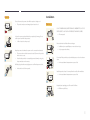
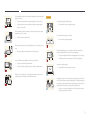

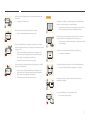


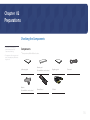
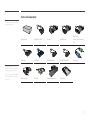
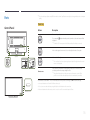
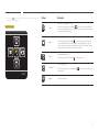
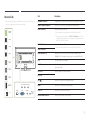
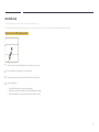
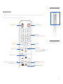
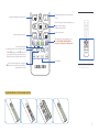
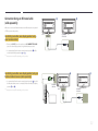
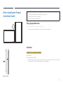
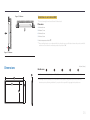
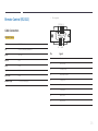
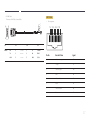
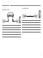
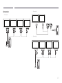

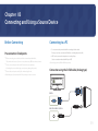

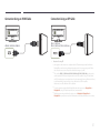
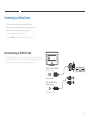


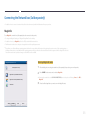
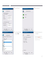
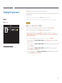
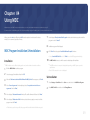
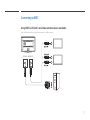
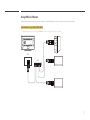


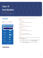


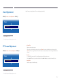
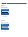

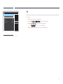
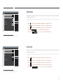
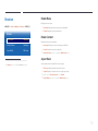
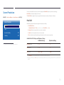


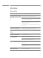


![[ED32D/ED40D/ED46D/ED55D] User Manual](http://vs1.manualzilla.com/store/data/005981977_1-5e9fcb879550bf5117f8a87507455499-150x150.png)