1
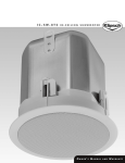
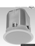
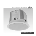
I C - 4 0 0 -T, I C - 5 2 5 -T & I C - 6 5 0 -T
IN-CEILING LOUDSPEAKERS
OWNER’S MANUAL
AND
WARRANT Y
I C - 4 0 0 - T ,
I C - 5 2 5 - T
&
I C - 6 5 0 - T
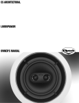
Thank you for purc hasing your Klipsc h IC-400-T,
IC-525-T or IC-650-T in-ceiling speakers.
The IC-400-T, IC-525-T and IC-650-T in-ceiling speakers have been
designed for music reinforcement applications. Unobtrusive,
these loudspeakers are engineered for easy, versatile installation.
The IC-400-T, IC-525-T and IC-650-T feature an internal transformer
for 70V/100V distributed-line systems. The transformer taps are
selected using a rotary switch located conveniently under the
grille. For applications where 8 ohm operation is required, the
transformer can be by-passed by using an optional connection
located on the back input terminal and selectin 8 Ohm on the
front switch.
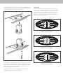
3. To install the tilebridge, fold the rail side of the ring back
upon itself using the spring tensioner on the reinforcement ring
to allow insertion into the cutout hole. Once it is inserted into
the cutout hole, release the reinforcement ring such that it
unfolds back to its normal position. Position tilebridge over
cutout hole, and insure that the tile rails rest on the t-grid struts.
Before installing your speakers take a moment to check the
contents of the cartons and make sure nothing has been
damaged in transit.
Contents Description
Q UANTIT Y
Speaker Modules
Grille
Reinforcement Ring
Rails
Cardboard Cutout Template and Paint Mask
Screws (Attach Rails to Reinforcement Ring)
3/
4" Adapter Fittings
2
2
2
4
2
8
2
Installation Guidelines
The IC-400-T, IC-525-T and IC-650-T include a tilebridge for use
when installing the loudspeaker into suspended ceilings or wherever additional reinforcement of the ceiling material is required.
The tilebridge and loudspeaker are designed such that installation may be accomplished where access above the ceiling is
not possible or may be difficult.
Installation
1. The tilebridge is composed of three parts—a reinforcement ring
and two rails. The two rails should be attached to the reinforcement ring using the four included screws as shown below.
Caution: Be sure to comply with any and all building codes
in your area.
2. To install your IC-400-T, IC-525-T or IC-650-T cut out a hole in the
ceiling using either the cardboard cutout template provided with
your speakers or consult the measurements below. Pull wiring
through hole.
I C - 4 0 0 - T, I C - 5 2 5 - T
9.125 " Ro u n d
IC-650-T
10.125 " Ro u n d
4. The wiring compartment is intended as a termination point
for the audio circuit. Access to this compartment is gained by
removing the terminal cover located on the back of the
speaker. The terminal cover will accept the appropriate
conduit/wire adapter (provided). Feed wires through
conduit/wire adapter and connect to the input terminal
according to the desired operation mode. Be sure to observe
proper polarity. Replace the terminal cover and tighten the
conduit/wire adapter to secure the wire.
Caution: When connecting 70V or 100V distributed
line systems, take care to ensure proper terminal
connection. Connection to the low impedance terminal could result in speaker damage, amplifier
damage, or both.
Seismic Tab
A seismic tab, located on the back of the speaker, is used
as a secondary security point. Some construction codes may
require its use. To utilize the seismic tab, run a support wire
from a secure point in the ceiling and attach it to the tab.
Be sure to consult the construction codes in your area.
Klipsch recommends the use of this tab in all installations as
a secondary means of support.
70V
1.875W
3.75W
7.5W
15W
100V
5. Insert the speaker into the cutout hole. With a #2 Phillips screwdriver, tighten the four dog clamps until they are seated securely
against the ceiling surface. Do not overtighten.
15W
7.5W
3.75W
70V
3.75W
7.5W
15W
100V
IC-400-T tap selectable
30W
15W
7.5W
30W
70V
7.5W
15W
30W
100V
IC-525-T tap selectable
60W
6. For installations using 70v/100v input connection, set the switch
on the front panel to the desired setting. For applications where 8
Ohm impedance is desired, the switch should be set to 8 Ohms.
Note: The speaker comes from the factory set at the lowest
output setting (highest impedance).
7. Using the flat of your hand, insert grille into speaker frame
making sure it is securely seated and flush.
IC-650-T tap selectable
60W
30W
15W
I N
-
C E I L I N G
S P E A K E R S
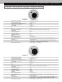
I C - 4 0 0 - T , I C - 5 2 5 - T & I C - 6 5 0 - T S P E C I F I C AT I O N S
IC-400-T
FREQUENCY RESPONSE
C O N T. P OW E R H A N D .
C A LC M A X C O N T. O U T P U T @ 1 M
SENSITIVIT Y 2.83 V/1M
C OV E R AG E
DI
Q
N O M I N A L I M P E DA N C E
DIAMETER
C U TO U T D I A M E T E R
OV E R A L L D E P T H
MOUNTING DEPTH
WEIGHT
I N P U T C O N N E C TO R S
T R A N S F O R M E R TA P S
FINISHES
TRANSDUCERS
E N C LO S U R E T U N I N G
70-20k Hz +/- 4 dB
50 watts (14.5V)
100 dB
86dB
80 degrees
8 dB
6.3
8 ohms, min 4.2 ohms when switch is set to 8 ohm position
9"
9.125"
8.313"
8"
6.25 lbs.
Te r m i n a l S t r i p
7 0 V: 15 W, 7. 5 W, 3 . 8 W, 1. 9 W
10 0 V: 15 W, 7. 5 W, 3 . 8 W
Black and White
5 " WO O F E R A N D 1 " T I TA N I U M D I A P H R AG M C O M P R E S S I O N
D R I V E R O N A 2 " RO U N D T R AC T R I X H O R N
Ve n t e d V i a A 1 " Tr a c t r i x p o r t
IC-525-T
FREQUENCY RESPONSE
C O N T. P OW E R H A N D .
C A LC M A X C O N T. O U T P U T @ 1 M
SENSITIVIT Y 2.83 V/1M
C OV E R AG E
DI
Q
N O M I N A L I M P E DA N C E
DIAMETER
C U TO U T D I A M E T E R
OV E R A L L D E P T H
MOUNTING DEPTH
WEIGHT
I N P U T C O N N E C TO R S
T R A N S F O R M E R TA P S
FINISHES
TRANSDUCERS
E N C LO S U R E T U N I N G
65-20k Hz +/- 4 dB
65 watts (16.5V)
104 dB
89dB
10 5 d e g r e e s
6.5 dB
4.5
8 ohms, min 4.2 ohms; switch set in 8 ohm position
9"
9.125"
9.188"
8.875"
8.25 lbs.
Te r m i n a l S t r i p
7 0 V: 3 0 W, 15 W, 7. 5 W, 3 . 8 W
10 0 V: 3 0 W, 15 W, 7. 5 W
Black and White
5 . 7 5 " WO O F E R A N D 1 " T I TA N I U M D I A P H R AG M C O M P R E S S I O N
D R I V E R O N A 3 . 5 " RO U N D X T M O D I F I E D T R AC T R I X H O R N
Ve n t e d V i a A 1 " Tr a c t r i x p o r t
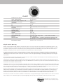
IC-650-T
FREQUENCY RESPONSE
C O N T. P OW E R H A N D .
C A LC M A X C O N T. O U T P U T @ 1 M
SENSITIVIT Y 2.83 V/1M
C OV E R AG E
DI
Q
N O M I N A L I M P E DA N C E
DIAMETER
C U TO U T D I A M E T E R
OV E R A L L D E P T H
MOUNTING DEPTH
WEIGHT
I N P U T C O N N E C TO R S
T R A N S F O R M E R TA P S
FINISHES
TRANSDUCERS
E N C LO S U R E T U N I N G
50-20k Hz +/- 4 dB
80 watts (18.8 V)
106 dB
90dB
10 5 d e g r e e s
6.5 dB
4.5
8 ohms, min 4.4 ohms; switch set in 8 ohm position
10"
10.125"
10.938"
10.625"
11. 2 5 l b s .
Te r m i n a l S t r i p
7 0 V: 6 0 W, 3 0 W, 15 W, 7. 5 W
10 0 V: 6 0 W, 3 0 W, 15 W
Black and White
6 . 5 " WO O F E R A N D 1 " T I TA N I U M D I A P H R AG M C O M P R E S S I O N
D R I V E R O N A 3 . 5 " RO U N D X T M O D I F I E D T R AC T R I X H O R N
Ve n t e d V i a A 1 " Tr a c t r i x p o r t
Klipsc h Limited Warranty
KLIPSCH, AUDIO TECHNOLOGIES ("KLIPSCH") warrants this product to be free from defects in materials and workmanship (subject to the
terms set forth below) for a period of five (5) years from the date of purchase. During the Warranty period, KLIPSCH will repair or replace
(at KLIPSCH’s option) this product or any defective parts (excluding electronics and amplifiers). For products that have electronics or
amplifiers, the Warranty on those parts is for a period of two (2) years from the date of purchase.
To obtain Warranty service, please contact the KLIPSCH authorized dealer from which you purchased this product. If your dealer is not
equipped to perform the repair of your KLIPSCH product, it can be returned, freight paid, to KLIPSCH for repair. Please call KLIPSCH at
1-800-KLIPSCH for instructions. You will need to ship this product in either its original packaging or packaging affording an equal degree
of protection.
Proof of purchase in the form of a bill of sale or receipted invoice, which is evidence that this product is within the Warranty period, must
be presented or included to obtain Warranty service.
This Warranty is invalid if (a) the factory-applied serial number has been altered or removed from this product or (b) this product was not
purchased from a KLIPSCH authorized dealer. You may call 1-800-KLIPSCH to confirm that you have an unaltered serial number and/or you
purchased from a KLIPSCH authorized dealer.
This Warranty does not cover cosmetic damage or damage due to misuse, abuse, negligence, acts of God, accident, commercial use or
modification of, or to any part of, the product. This Warranty does not cover damage due to improper operation, maintenance or installation, or attempted repair by anyone other than KLIPSCH or a KLIPSCH dealer which is authorized to do KLIPSCH warranty work. Any unauthorized repairs will void this Warranty. This Warranty does not cover product sold AS IS or WITH ALL FAULTS.
REPAIRS OR REPLACEMENTS AS PROVIDED UNDER THIS WARRANTY ARE THE EXCLUSIVE REMEDY OF THE CONSUMER. KLIPSCH SHALL NOT BE
LIABLE FOR ANY INCIDENTAL OR CONSEQUENTIAL DAMAGES FOR BREACH OF ANY EXPRESS OR IMPLIED WARRANTY ON THIS PRODUCT.
EXCEPT TO THE EXTENT PROHIBITED BY LAW, THIS WARRANTY IS EXCLUSIVE AND IN LIEU OF ALL OTHER EXPRESS AND IMPLIED WARRANTIES
WHATSOEVER, INCLUDING BUT NOT LIMITED TO, THE WARRANTY OF MERCHANTABILITY AND FITNESS FOR A PRACTICAL PURPOSE.
Some states do not allow the exclusion or limitation of incidental or consequential damages or implied warranties so the above exclusions
may not apply to you. This Warranty gives you specific legal rights, and you may have other rights, which vary from state to state.
©2007 Klipsch Group, Inc. All Rights Reserved
Specifications Subject to Engineering Changes
3502 Woodview Trace
Indianapolis, Indiana 46268 USA
1. 800 . KLIPSCH • www.klipsch.com
1008997