1
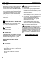
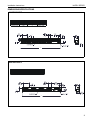
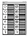
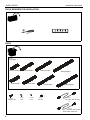
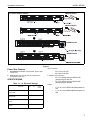
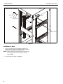
INSTALLATION INSTRUCTIONS
Instrucciones de instalación
Installationsanleitung
Instruções de Instalação
NAPDV06XXPC
NAPDV06XX2
NAPDV12XXPC
NAPDV12XX2
Istruzioni di installazione
Installatie-instructies
Instructions d´installation
NAPDV18XXPC
NAPDV18XX2
NAPDV24XXPC
NAPDV24XX2
NAPDV Power Strips
Spanish Product Description
German Product Description
Portuguese Product Description
Italian Product Description
Dutch Product Description
French Product Description
NAPDV SERIES
NAPDV SERIES
Installation Instructions
DISCLAIMER
Milestone AV Technologies, and its affiliated corporations and
subsidiaries (collectively, "Milestone"), intend to make this
manual accurate and complete. However, Milestone makes no
claim that the information contained herein covers all details,
conditions or variations, nor does it provide for every possible
contingency in connection with the installation or use of this
product. The information contained in this document is subject
to change without notice or obligation of any kind. Milestone
makes no representation of warranty, expressed or implied,
regarding the information contained herein. Milestone assumes
no responsibility for accuracy, completeness or sufficiency of
the information contained in this document.
Chief® is a registered trademark of Milestone AV Technologies.
All rights reserved.
IMPORTANT SAFETY INSTRUCTIONS
WARNING alerts you to the possibility of serious
injury or death if you do not follow the instructions.
CAUTION Avoid potential personal injuries
and property damage!
1.
Elevated Operating Ambient - If installed in a closed or
multi-unit rack assembly, the operating ambient
temperature of the rack environment may be greater than
room ambient. Therefore, consideration should be given to
installing the equipment in an environment compatible with
the maximum ambient temperature (0-40°C/32-104°F)
specified by the manufacturer.
2.
Reduced Air Flow - Installation of the equipment in a rack
should be such that the amount of air flow required for safe
operation of the equipment is not compromised.
3.
Circuit Overloading - Consideration should be given to the
connection of the equipment to the supply circuit and the
effect that overloading of the circuits might have on
overcurrent protection and supply wiring. Appropriate
consideration of equipment nameplate ratings should be
used when addressing this concern.
4.
Reliable Earthing - Reliable earthing of rack-mounted
equipment should be maintained. Particular attention
should be given to supply connections other than direct
connections to the branch circuit (e.g. use of power strips).
NOTE: This system has no user serviceable parts.
WARNING: The hardwired power strips (15A
CAUTION alerts you to the possibility of
damage or destruction of equipment if you do not follow the
corresponding instructions.
WARNING: FAILURE TO READ AND
FOLLOW THE FOLLOWING INSTRUCTIONS CAN RESULT
IN SERIOUS PERSONAL INJURY, DAMAGE TO EQUIPMENT
OR VOIDING OF FACTORY WARRANTY. It is the installer’s
responsibility to make sure all components are properly
assembled and installed using the instructions provided.
READ ALL INSTRUCTIONS BEFORE USING THIS
PRODUCT!!!!
DANGER: TO REDUCE THE RISK OF
ELECTRIC SHOCK:
2
1.
Use only in dry locations indoors.
2.
Do not plug into another relocatable power tap.
3.
Do not install this device if there is not at least 10 meters
(30 ft) or more of wire between the electrical outlet and the
electrical service panel.
4.
The input plug of this power tap is intended to serve as the
disconnect device, it shall be easily accessible and
withdrawn.
and 20A) do NOT contain internal circuit breaker protection.
The installer must ensure that the input of these power strips is
connected individually to a readily accessible electrical service
panel that is protected with a UL Listed 15A (maximum load)
circuit breaker for the 15A strip or 20A (maximum load) circuit
breaker for the 20A strip for overload protection of the power
strip.
--SAVE THESE INSTRUCTIONS--
Installation Instructions
NAPDV SERIES
DIMENSIONS/SPECIFICATIONS
NAPDVXX15PC
0.75
19.1
3.31
84.1
0.28
7.1
"A"
NAPDVXX20PC
0.75
19.1
3.31
84.1
0.28
7.1
"A"
3
NAPDV SERIES
Installation Instructions
DIMENSIONS/SPECIFICATIONS (CONTINUED)
NAPDVXX152
4.00
101.6
0.75
19.1
4.12
104.7
0.28
7.1
"A"
"B"
NAPDVXX202
0.75
19.1
4.40
111.7
0.28
7.1
"A"
"B"
4
Installation Instructions
NAPDV SERIES
LEGEND
Tighten Fastener
Pencil Mark
Apretar elemento de fijación
Marcar con lápiz
Befestigungsteil festziehen
Stiftmarkierung
Apertar fixador
Marcar com lápis
Serrare il fissaggio
Segno a matita
Bevestiging vastdraaien
Potloodmerkteken
Serrez les fixations
Marquage au crayon
Loosen Fastener
Drill Hole
Aflojar elemento de fijación
Perforar
Befestigungsteil lösen
Bohrloch
Desapertar fixador
Fazer furo
Allentare il fissaggio
Praticare un foro
Bevestiging losdraaien
Gat boren
Desserrez les fixations
Percez un trou
Phillips Screwdriver
Adjust
Destornillador Phillips
Ajustar
Kreuzschlitzschraubendreher
Einstellen
Chave de fendas Phillips
Ajustar
Cacciavite a stella
Regolare
Kruiskopschroevendraaier
Afstellen
Tournevis à pointe cruciforme
Ajuster
Open-Ended Wrench
Remove
Llave de boca
Quitar
Gabelschlüssel
Entfernen
Chave de bocas
Remover
Chiave a punte aperte
Rimuovere
Steeksleutel
Verwijderen
Clé à fourche
Retirez
By Hand
Optional
A mano
Opcional
Von Hand
Optional
Com a mão
Opcional
A mano
Opzionale
Met de hand
Optie
À la main
En option
Hex-Head Wrench
Security Wrench
Llave de cabeza hexagonal
Llave de seguridad
Sechskantschlüssel
Sicherheitsschlüssel
Chave de cabeça sextavada
Chave de segurança
Chiave esagonale
Chiave di sicurezza
Zeskantsleutel
Veiligheidssleutel
Clé à tête hexagonale
Clé de sécurité
5
NAPDV SERIES
Installation Instructions
TOOLS REQUIRED FOR INSTALLATION
#2
PARTS
A (1)
[Power Strip]
NAPDV06XXPC
NAPDV12XXPC
NAPDV12XX2
NAPDV06XX2
B (3)
#10-32 X 3/4"
NAPDV18XXPC
C (3)
#10
D (3)
#10
NAPDV18XX2
E (3)
#10-32"
NAPDV24XXPC
NAPDV24XX2
F (1)*
[6’ power cable for 15A]
or
G (1)*
[6’ power cable for 20A]
*power cable models only
6
Installation Instructions
NAPDV SERIES
NAPDV1215PC
(12 outlet models shown)
1
NAPDV1220PC
1
2
NAPDV12152
2
NAPDV12202
Figure 1
Power Strip Features
Input Connection:
1.
Reset Switch: Resettable circuit breaker. (power cable
models only)
2.
Dual Circuit: Two equal circuits per hardwired box.
(hardwired models only)
•
•
IEC C14 for the 15A
IEC C20 for the 20A
6’ supplied cord connections:
•
SPECIFICATIONS
•
Table 1-1: UL Electrical Ratings
IEC C13 (straight plug) to NEMA5-15P
(straight plug) for the 15A
IEC C19 (straight plug) to NEMA5-20P
(straight plug) for the 20A
Outlets:
Max load
VAC
Hz
power
output
•
15A power
cable models
12A
125
60
1500W
•
20A power
cable models
16A
125
60
2000W
15A hardwired
models
15A (per circuit)
125
60
1875W
20A hardwired
models
20A (per circuit)
125
60
2500W
6, 12, 18 or 24 x NEMA-15R Receptacles for
15A
6, 12, 18 or 24 x NEMA-20R Receptacles for
20A
7
NAPDV SERIES
Installation Instructions
(NAPDV06XXPC SHOWN)
(E) x 2 or 3
1
(B) x 3
(D) x 2 or 3
(C) x 2 or 3
(A)
rack (example)
Figure 2
Installation to Rack
1.
Use two or three #10-32 x 3/4" Phillips screws (B), #10
washers, #10 lock washers (D) and #10-32 lock nuts (E) to
secure power strip (A) to rack. (See Figure 2)
NOTE: Quantity of hardware used in Step 1 will depend on the
mounting application and the number of mounting
holes available.
2.
8
Connect power strip cables as applicable.
Installation Instructions
NAPDV SERIES
9
NAPDV SERIES
10
Installation Instructions
Installation Instructions
NAPDV SERIES
11
NAPDV SERIES
Installation Instructions
USA/International
Europe
Chief Manufacturing, a products division
of Milestone AV Technologies
8800-002186 Rev01
2012 Milestone AV Technologies, a
Duchossois Group Company
www.chiefmfg.com
12/12
Asia Pacific
A
P
F
A
P
F
A
6436 City West Parkway, Eden Prairie, MN 55344
800.582.6480 / 952.225.6000
877.894.6918 / 952.894.6918
Franklinstraat 14, 6003 DK Weert, Netherlands
+31 (0) 495 580 852
+31 (0) 495 580 845
Office No. 1 on 12/F, Shatin Galleria
18-24 Shan Mei Street
Fotan, Shatin, Hong Kong
P 852 2145 4099
F 852 2145 4477