1
TL-SG3210/TL-SG3216/TL-SG3424
JetStream L2 Managed Switch
REV2.0.0
1910010917
COPYRIGHT & TRADEMARKS
Specifications are subject to change without notice.
is a registered trademark of
TP-LINK TECHNOLOGIES CO., LTD. Other brands and product names are trademarks or
registered trademarks of their respective holders.
No part of the specifications may be reproduced in any form or by any means or used to make any
derivative such as translation, transformation, or adaptation without permission from TP-LINK
TECHNOLOGIES CO., LTD. Copyright © 2013 TP-LINK TECHNOLOGIES CO., LTD. All rights
reserved.
http://www.tp-link.com
I
CONTENTS
Preface
.............................................................................................................. 1
Chapter 1
Using the CLI......................................................................................... 4
1.1
Accessing the CLI ...........................................................................................................4
1.1.1
Logon by a console port .......................................................................................4
1.1.2
Logon by Telnet ....................................................................................................6
1.2
CLI Command Modes ...................................................................................................10
1.3
Security Levels .............................................................................................................12
1.4
Conventions ..................................................................................................................13
1.4.1
Format Conventions ...........................................................................................13
1.4.2
Special Characters .............................................................................................13
1.4.3
Parameter Format ..............................................................................................13
Chapter 2
User Interface...................................................................................... 15
enable....................................................................................................................................15
enable password ...................................................................................................................15
disable ...................................................................................................................................16
configure................................................................................................................................16
exit.........................................................................................................................................16
end ........................................................................................................................................17
Chapter 3
IEEE 802.1Q VLAN Commands.......................................................... 18
vlan........................................................................................................................................18
interface vlan .........................................................................................................................18
name .....................................................................................................................................19
switchport mode ....................................................................................................................19
switchport access vlan...........................................................................................................20
switchport trunk allowed vlan.................................................................................................20
switchport general allowed vlan.............................................................................................21
switchport pvid.......................................................................................................................22
show vlan summary...............................................................................................................22
show vlan brief ......................................................................................................................23
show vlan ..............................................................................................................................23
Chapter 4
MAC-based VLAN Commands............................................................ 24
mac-vlan mac-address ..........................................................................................................24
show mac-vlan ......................................................................................................................24
II
Chapter 5
Protocol-based VLAN Commands....................................................... 26
protocol-vlan template ...........................................................................................................26
protocol-vlan vlan ..................................................................................................................27
protocol-vlan group................................................................................................................27
show protocol-vlan template..................................................................................................28
show protocol-vlan vlan .........................................................................................................28
Chapter 6
Voice VLAN Commands ...................................................................... 29
voice vlan ..............................................................................................................................29
voice vlan aging time .............................................................................................................29
voice vlan priority...................................................................................................................30
voice vlan mac-address.........................................................................................................30
switchport voice vlan mode ...................................................................................................31
switchport voice vlan security ................................................................................................32
show voice vlan .....................................................................................................................32
show voice vlan oui ...............................................................................................................33
show voice vlan switchport ....................................................................................................33
Chapter 7
GVRP Commands ............................................................................... 34
gvrp(global) ...........................................................................................................................34
gvrp(interface) .......................................................................................................................34
gvrp registration.....................................................................................................................35
gvrp timer ..............................................................................................................................35
show gvrp global ...................................................................................................................36
show gvrp interface ...............................................................................................................37
Chapter 8
Etherchannel Commands .................................................................... 38
channel-group .......................................................................................................................38
port-channel load-balance .....................................................................................................39
lacp system-priority ...............................................................................................................39
lacp port-priority.....................................................................................................................40
show etherchannel ................................................................................................................40
show etherchannel load-balance...........................................................................................41
show lacp ..............................................................................................................................41
show lacp sys-id ....................................................................................................................42
Chapter 9
User Manage Commands.................................................................... 43
user name .............................................................................................................................43
user access-control ip-based.................................................................................................44
III
user access-control mac-based.............................................................................................44
user access-control port-based .............................................................................................45
user max-number ..................................................................................................................46
user idle-timeout....................................................................................................................46
line.........................................................................................................................................47
password ...............................................................................................................................48
login.......................................................................................................................................48
login local ..............................................................................................................................49
show user account-list ...........................................................................................................49
show user configuration.........................................................................................................50
Chapter 10 Binding Table Commands.................................................................... 51
ip source binding ...................................................................................................................51
ip dhcp snooping ...................................................................................................................52
ip dhcp snooping global.........................................................................................................52
ip dhcp snooping information option ......................................................................................53
ip dhcp snooping information strategy ...................................................................................54
ip dhcp snooping information remote-id.................................................................................55
ip dhcp snooping information circuit-id ..................................................................................55
ip dhcp snooping trust ...........................................................................................................56
ip dhcp snooping mac-verify..................................................................................................56
ip dhcp snooping limit rate.....................................................................................................57
ip dhcp snooping decline .......................................................................................................58
show ip source binding ..........................................................................................................58
show ip dhcp snooping ..........................................................................................................59
show ip dhcp snooping information .......................................................................................59
show ip dhcp snooping interface gigabitEthernet ..................................................................59
Chapter 11
ARP Inspection Commands................................................................. 61
ip arp inspection(global) ........................................................................................................61
ip arp inspection trust ............................................................................................................61
ip arp inspection(interface) ....................................................................................................62
ip arp inspection limit-rate......................................................................................................63
ip arp inspection recover .......................................................................................................63
show ip arp inspection ...........................................................................................................64
show ip arp inspection interface ............................................................................................64
show ip arp inspection statistics ............................................................................................65
clear ip arp inspection statistics.............................................................................................65
IV
Chapter 12 DoS Defend Command ....................................................................... 66
ip dos-prevent........................................................................................................................66
ip dos-prevent type ................................................................................................................66
show ip dos-prevent ..............................................................................................................67
Chapter 13 IEEE 802.1X Commands..................................................................... 68
dot1x system-auth-control .....................................................................................................68
dot1x auth-method ................................................................................................................68
dot1x guest-vlan(global) ........................................................................................................69
dot1x quiet-period..................................................................................................................70
dot1x timeout.........................................................................................................................70
dot1x max-reauth-req ............................................................................................................71
dot1x......................................................................................................................................71
dot1x guest-vlan(interface) ....................................................................................................72
dot1x port-control ..................................................................................................................72
dot1x port-method .................................................................................................................73
radius.....................................................................................................................................74
radius server-account ............................................................................................................75
show dot1x global..................................................................................................................75
show dot1x interface .............................................................................................................76
show radius accounting .........................................................................................................76
show radius authentication ....................................................................................................77
Chapter 14 System Log Commands ...................................................................... 78
logging buffer.........................................................................................................................78
logging file flash.....................................................................................................................79
clear logging ..........................................................................................................................79
logging host index .................................................................................................................80
show logging local-config ......................................................................................................81
show logging loghost .............................................................................................................81
show logging buffer ...............................................................................................................81
show logging flash.................................................................................................................82
Chapter 15 SSH Commands.................................................................................. 83
ip ssh server ..........................................................................................................................83
ip ssh version ........................................................................................................................83
ip ssh timeout ........................................................................................................................84
ip ssh max-client....................................................................................................................84
V
ip ssh download.....................................................................................................................85
show ip ssh............................................................................................................................85
Chapter 16 SSL Commands .................................................................................. 87
ip http secure-server..............................................................................................................87
ip http secure-server download certificate .............................................................................87
ip http secure-server download key .......................................................................................88
show ip http secure-server ....................................................................................................89
Chapter 17 MAC Address Commands ................................................................... 90
mac address-table static........................................................................................................90
mac address-table aging-time ...............................................................................................91
mac address-table filtering ....................................................................................................91
mac address-table max-mac-count .......................................................................................92
show mac address-table address ..........................................................................................93
show mac address-table aging-time ......................................................................................93
show mac address-table max-mac-count interface gigabitEthernet ......................................94
show mac address-table interface gigabitEthernet ................................................................94
show mac address-table mac-num........................................................................................95
show mac address-table mac................................................................................................95
show mac address-table vlan ................................................................................................96
Chapter 18 System Configuration Commands ....................................................... 97
system-time manual ..............................................................................................................97
system-time ntp .....................................................................................................................97
system-time dst predefined ...................................................................................................99
system-time dst date ...........................................................................................................100
system-time dst recurring ....................................................................................................100
hostname.............................................................................................................................101
location ................................................................................................................................102
contact-info..........................................................................................................................102
ip management-vlan ............................................................................................................103
ip address............................................................................................................................103
ip address-alloc dhcp ..........................................................................................................104
ip address-alloc bootp .........................................................................................................105
reset ....................................................................................................................................105
reboot ..................................................................................................................................105
copy running-config startup-config ......................................................................................106
copy startup-config tftp ........................................................................................................106
VI
copy tftp startup-config ........................................................................................................107
firmware upgrade ................................................................................................................107
ping .....................................................................................................................................108
tracert ..................................................................................................................................109
loopback interface ...............................................................................................................109
show system-time................................................................................................................ 110
show system-time dst .......................................................................................................... 110
show system-time ntp.......................................................................................................... 111
show system-info................................................................................................................. 111
show cable-diagnostics interface......................................................................................... 111
Chapter 19 Ethernet Configuration Commands ....................................................113
interface gigabitEthernet...................................................................................................... 113
interface range gigabitEthernet ........................................................................................... 113
description ........................................................................................................................... 114
shutdown ............................................................................................................................. 114
flow-control .......................................................................................................................... 115
media-type........................................................................................................................... 115
duplex.................................................................................................................................. 116
speed................................................................................................................................... 116
storm-control broadcast....................................................................................................... 117
storm-control multicast ........................................................................................................ 118
storm-control unicast ........................................................................................................... 118
bandwidth ............................................................................................................................ 119
clear counters......................................................................................................................120
show interface status...........................................................................................................120
show interface counters.......................................................................................................120
show interface description ...................................................................................................121
show interface flowcontrol ...................................................................................................121
show interface configuration................................................................................................122
show storm-control ..............................................................................................................122
show bandwidth...................................................................................................................123
Chapter 20 QoS Commands .................................................................................124
qos ......................................................................................................................................124
qos dscp ..............................................................................................................................124
qos queue cos-map .............................................................................................................125
qos queue dscp-map ...........................................................................................................126
VII
qos queue mode..................................................................................................................127
show qos interface ..............................................................................................................128
show qos cos-map ..............................................................................................................128
show qos dscp-map ............................................................................................................129
show qos queue mode ........................................................................................................129
show qos status...................................................................................................................130
Chapter 21 Port Mirror Commands .......................................................................131
monitor session destination interface ..................................................................................131
monitor session source interface.........................................................................................132
show monitor session ..........................................................................................................133
Chapter 22 Port Isolation Commands ...................................................................134
port isolation ........................................................................................................................134
show port isolation interface ................................................................................................134
Chapter 23 Loopback Detection Commands ........................................................136
loopback-detection(global) ..................................................................................................136
loopback-detection interval..................................................................................................136
loopback-detection recovery-time........................................................................................137
loopback-detection(interface) ..............................................................................................137
loopback-detection config....................................................................................................138
loopback-detection recover .................................................................................................138
show loopback-detection global ..........................................................................................139
show loopback-detection interface ......................................................................................139
Chapter 24 ACL Commands .................................................................................141
time-range ...........................................................................................................................141
absolute...............................................................................................................................141
periodic................................................................................................................................142
holiday .................................................................................................................................143
holiday(global) .....................................................................................................................143
access-list create.................................................................................................................144
mac access-list....................................................................................................................144
access-list standard.............................................................................................................145
access-list extended ............................................................................................................146
rule ......................................................................................................................................147
access-list policy name........................................................................................................148
access-list policy action .......................................................................................................149
VIII
redirect interface..................................................................................................................149
s-condition ...........................................................................................................................150
s-mirror ................................................................................................................................150
qos-remark ..........................................................................................................................151
access-list bind(interface)....................................................................................................151
access-list bind(vlan) ...........................................................................................................152
show time-range..................................................................................................................152
show holiday........................................................................................................................153
show access-list ..................................................................................................................153
show access-list policy ........................................................................................................154
show access-list bind ..........................................................................................................154
Chapter 25 MSTP Commands ..............................................................................155
spanning-tree(global)...........................................................................................................155
spanning-tree(interface) ......................................................................................................155
spanning-tree common-config .............................................................................................156
spanning-tree mode.............................................................................................................157
spanning-tree mst configuration ..........................................................................................157
instance ...............................................................................................................................158
name ...................................................................................................................................159
revision ................................................................................................................................159
spanning-tree mst instance .................................................................................................160
spanning-tree mst................................................................................................................160
spanning-tree priority...........................................................................................................161
spanning-tree tc-defend.......................................................................................................162
spanning-tree timer..............................................................................................................162
spanning-tree hold-count.....................................................................................................163
spanning-tree max-hops ......................................................................................................164
spanning-tree bpdufilter.......................................................................................................164
spanning-tree bpduguard ....................................................................................................165
spanning-tree guard loop.....................................................................................................165
spanning-tree guard root .....................................................................................................166
spanning-tree guard tc.........................................................................................................166
spanning-tree mcheck .........................................................................................................167
show spanning-tree active...................................................................................................167
show spanning-tree bridge ..................................................................................................168
show spanning-tree interface ..............................................................................................168
show spanning-tree interface-security .................................................................................169
IX
show spanning-tree mst ......................................................................................................170
Chapter 26 IGMP Commands ...............................................................................171
ip igmp snooping(global) .....................................................................................................171
ip igmp snooping(interface) .................................................................................................171
ip igmp snooping immediate-leave ......................................................................................172
ip igmp snooping drop-unknown..........................................................................................172
ip igmp snooping vlan-config ...............................................................................................173
ip igmp snooping multi-vlan-config ......................................................................................174
ip igmp snooping filter add-id...............................................................................................175
ip igmp snooping filter(global)..............................................................................................176
ip igmp snooping filter(interface) .........................................................................................176
ip igmp snooping filter maxgroup.........................................................................................177
ip igmp snooping filter mode................................................................................................177
show ip igmp snooping ........................................................................................................178
show ip igmp snooping interface .........................................................................................178
show ip igmp snooping vlan ................................................................................................179
show ip igmp snooping multi-vlan........................................................................................180
show ip igmp snooping groups ............................................................................................180
show ip igmp snooping filter ................................................................................................181
Chapter 27 SNMP Commands..............................................................................182
snmp-server ........................................................................................................................182
snmp-server view ................................................................................................................182
snmp-server group ..............................................................................................................183
snmp-server user ................................................................................................................184
snmp-server community ......................................................................................................186
snmp-server host.................................................................................................................186
snmp-server engineID .........................................................................................................188
snmp-server traps snmp......................................................................................................188
snmp-server traps link-status...............................................................................................189
snmp-server traps................................................................................................................190
snmp-server traps mac........................................................................................................191
snmp-server traps vlan ........................................................................................................191
rmon history.........................................................................................................................192
rmon event ..........................................................................................................................193
rmon alarm ..........................................................................................................................194
show snmp-server ...............................................................................................................195
X
show snmp-server view .......................................................................................................196
show snmp-server group .....................................................................................................196
show snmp-server user .......................................................................................................196
show snmp-server community.............................................................................................197
show snmp-server host .......................................................................................................197
show snmp-server engineID................................................................................................197
show rmon history ...............................................................................................................198
show rmon event .................................................................................................................198
show rmon alarm.................................................................................................................199
Chapter 28 Cluster Commands.............................................................................200
cluster ndp...........................................................................................................................200
cluster ntdp ..........................................................................................................................201
cluster explore .....................................................................................................................202
cluster..................................................................................................................................202
cluster candidate .................................................................................................................203
cluster individual..................................................................................................................203
show cluster ndp..................................................................................................................204
show cluster ntdp.................................................................................................................204
show cluster neighbour........................................................................................................205
show cluster manage role....................................................................................................205
XI
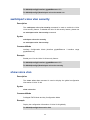
Preface
This Guide is intended for network administrator to provide referenced information about CLI
(Command Line Interface). The switch or TL-SG3210/TL-SG3216/TL-SG3424 mentioned in this
Guide stands for TL-SG3210/TL-SG3216/TL-SG3424 JetStream L2 Managed Switch without any
explanation.
The three devices of TL-SG3210, TL-SG3216 and TL-SG3424 are sharing this Guide. For
simplicity, we will take TL-SG3424 for example throughout this Guide. TL-SG3210, TL-SG3216
and TL-SG3424 just differ in the number of LED indicators and ports and all figures in this guide
are of TL-SG3424.
Overview of this Guide
Chapter 1: Using the CLI
Provide information about how to use the CLI, CLI Command Modes, Security Levels and some
Conventions.
Chapter 2: User Interface
Provide information about the commands used to switch between five CLI Command Modes.
Chapter 3: IEEE 802.1Q VLAN Commands
Provide information about the commands used for configuring IEEE 802.1Q VLAN.
Chapter 4: MAC-Based VLAN Commands
Provide information about the commands used for configuring MAC-Based VLAN.
Chapter 5: Protocol-Based VLAN Commands
Provide information about the commands used for configuring Protocol-Based VLAN.
Chapter 6: Voice VLAN Commands
Provide information about the commands used for configuring Voice VLAN.
Chapter 7: GVRP Commands
Provide information about the commands used for configuring GVRP (GARP VLAN registration
protocol).
Chapter 8: Etherchannel Commands
Provide information about the commands used for configuring LAG (Link Aggregation Group) and
LACP (Link Aggregation Control Protocol).
Chapter 9: User Manage Commands
Provide information about the commands used for user management.
Chapter 10: Binding Table Commands
Provide information about the commands used for binding the IP address, MAC address, VLAN
and the connected Port number of the Host together. Besides it also provide information about the
1
commands used for monitoring the process of the Host obtaining the IP address from DHCP
server, and record the IP address, MAC address, VLAN and the connected Port number of the
Host for automatic binding.
Chapter 11: ARP Inspection Commands
Provide information about the commands used for protecting the switch from the ARP cheating or
ARP Attack.
Chapter 12: DoS Defend Command
Provide information about the commands used for DoS defend and detecting the DoS attack.
Chapter 13: IEEE 802.1X Commands
Provide information about the commands used for configuring IEEE 802.1X function.
Chapter 14: System Log Commands
Provide information about the commands used for configuring system log.
Chapter 15: SSH Commands
Provide information about the commands used for configuring and managing SSH (Security
Shell).
Chapter 16: SSL Commands
Provide information about the commands used for configuring and managing SSL (Secure
Sockets Layer).
Chapter 17: MAC Address Commands
Provide information about the commands used for Address configuration.
Chapter 18: System Configuration Commands
Provide information about the commands used for configuring the System information and System
IP, reboot and reset the switch, upgrade the switch system and commands used for device
diagnose, including loopback test and cable test.
Chapter 19: Ethernet Configuration Commands
Provide information about the commands used for configuring the Bandwidth Control, Negotiation
Mode, and Storm Control for Ethernet ports.
Chapter 20: QoS Commands
Provide information about the commands used for configuring the QoS function.
Chapter 21: Port Mirror Commands
Provide information about the commands used for configuring the Port Mirror function.
Chapter 22: Port Isolation Commands
Provide information about the commands used for configuring the Port Isolation function.
Chapter 23: Loopback Detection Commands
2
Provide information about the commands used for configuring the Loopback Detection function.
Chapter 24: ACL Commands
Provide information about the commands used for configuring the ACL (Access Control List).
Chapter 25: MSTP Commands
Provide information about the commands used for configuring the MSTP (Multiple Spanning Tree
Protocol).
Chapter 26: IGMP Commands
Provide information about the commands used for configuring the IGMP Snooping (Internet Group
Management Protocol Snooping).
Chapter 27: SNMP Commands
Provide information about the commands used for configuring the SNMP (Simple Network
Management Protocol) functions.
Chapter 28: Cluster Commands
Provide information about the commands used for configuring the Cluster Management function.
3
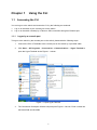
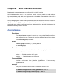
Chapter 1
1.1
Using the CLI
Accessing the CLI
You can log on to the switch and access the CLI by the following two methods:
1.
Log on to the switch by the console port on the switch.
2.
Log on to the switch remotely by a Telnet or SSH connection through an Ethernet port.
1.1.1 Logon by a console port
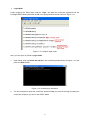
To log on to the switch by the console port on the switch, please take the following steps:
1.
Connect the PCs or Terminals to the console port on the switch by a provided cable.
2.
Click Start → All Programs → Accessories→ Communications → Hyper Terminal to
open the Hyper Terminal as the Figure 1-1 shown.
Figure 1-1 Open Hyper Terminal
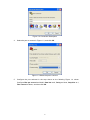
3.
The Connection Description Window will prompt as Figure 1-2 shown. Enter a name into
the Name field and click OK.
4
Figure 1-2 Connection Description
4.
Select the port to connect in Figure 1-3, and click OK.
Figure 1-3 Select the port to connect
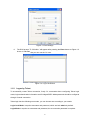
5.
Configure the port selected in the step above as the following Figure 1-4 shown.
Configure Bits per second as 38400, Data bits as 8, Parity as None, Stop bits as 1,
Flow control as None, and then click OK.
5
Figure 1-4 Port Settings
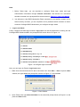
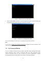
6.
The DOS prompt” TL-SG3424>” will appear after pressing the Enter button as Figure 1-5
shown. It indicates that you can use the CLI now.
Figure 1-5 Log in the Switch
1.1.2 Logon by Telnet
To successfully create Telnet connection, firstly CLI commands about configuring Telnet login
mode, login authentication information and Privileged EXEC Mode password should be configured
through Console connection.
Telnet login has the following two modes, you can choose one according to your needs:
Login local Mode: It requires username and password, which are both admin by default.
Login Mode: It requires no username and password, but a connection password is required.
6
Note:
1. Before Telnet login, you are required to configure Telnet login mode and login
authentication information through Console connection. The relevant CLI commands
should be entered in the prompted DOS screen shown in Figure 1-5 Log in the Switch.
2. You will enter to User EXEC Mode after Telnet connection is successfully created, but for
switch security concerns, you are required to set a password which functions to further
access to Privileged EXEC Mode when you configure the login mode.
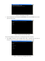
Login Local Mode
Firstly, configure the Telnet login mode as “login local” and set the password for entering into the
Privileged EXEC Mode as 123 in the prompted DOS screen shown in Figure 1-6.
Figure 1-6 Configure login local mode
Now, you can logon by Telnet in login local mode.
1.
Make sure the switch and the PC are in the same LAN. Click Start → Run to open the Run
window, and type cmd in the prompt Run window as Figure 1-7 and click OK.
Figure 1-7 Run Window
2.
Open Telnet, then type telnet 192.168.0.1 in the command prompt shown as Figure 1-8, and
press the Enter button.
7
Figure 1-8 Connecting to the Switch
3.
Type the default user name and password admin/admin, then press the Enter button so as to
enter User EXEC Mode.
Figure 1-9 Enter into the User EXEC Mode
Now you can manage your switch with CLI commands through Telnet connection.
4.
Type enable command to enter Privileged EXEC Mode. A password that you have set
through Console port connection is required. Here the password is set as 123.
Figure 1-10 Enter into the Privileged EXEC Mode
8
Login Mode
Firstly configure the Telnet login mode as “login”, and both the connection password and the
Privileged EXEC Mode password as 123 in the prompted DOS screen shown in Figure 1-11.
Figure 1-11 Configure login mode
Now, you can logon by Telnet in login mode:
1.
Open Telnet, then type telnet 192.168.0.1 in the command prompt shown as Figure 1-12, and
press the Enter button.
Figure 1-12 Connecting to the Switch
2.
You are prompted to enter the connection password 123 you have set through Console port
connection, and then you are in User EXEC Mode.
9
Figure 1-13 Enter into the User EXEC Mode
3.
When entering enable command to access Privileged EXEC Mode, you are required to give
the password 123 you have set through Console port connection.
Figure 1-14 Enter into the Privileged EXEC Mode
Now you can manage your switch with CLI commands through Telnet connection.
Note:
You can refer to Chapter 9 User Manage Commands for detailed commands information of the
Telnet connection configuration.
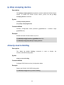
1.2
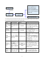
CLI Command Modes
The CLI is divided into different command modes: User EXEC Mode, Privileged EXEC Mode,
Global Configuration Mode, Interface Configuration Mode and VLAN Configuration Mode.
Interface Configuration Mode can also be divided into Interface gigabitEthernet, Interface
link-aggregation and some other modes, which is shown as the following diagram.
10
Interface Configuration Mode
Interface gigabitEthernet
User EXEC Mode
Interface link-aggregation
Interface range gigabitEthernet
password
Interface range link-aggregation
Interface vlan
Privileged EXEC
Global Configuration
Mode
Mode
……
VLAN Configuration Mode
The following table gives detailed information about the Accessing path, Prompt of each mode and
how to exit the current mode and access the next mode.
Mode
Accessing Path
User EXEC
Mode
Primary mode once it
is connected with the
switch.
Privileged
EXEC Mode
Use
the
enable
command to enter this
mode from User EXEC
mode.
Global
Configuration
Mode
Use the configure
command to enter this
mode from Privileged
EXEC mode.
Prompt
Logout or Access the next mode
TL-SG3424>
Use the exit command to disconnect the
switch (except that the switch is
connected through the Console port).
Use the enable command to access
Privileged EXEC mode.
TL-SG3424#
Enter the disable or the exit command
to return to User EXEC mode.
Enter configure command to access
Global Configuration mode.
Use the exit or the end command or
press Ctrl+Z to return to Privileged
EXEC mode.
TL-SG3424(config)#
Use the interface gigabitEthernet port
or interface range gigabitEthernet
port-list command to access interface
Configuration mode.
Use the vlan vlan-list to access VLAN
Configuration mode.
Interface
Configuration
Mode
Use the interface
gigabitEthernet port
or interface range
gigabitEthernet
port-list command to
enter this mode from
Global Configuration
mode.
TL-SG3424(config-if)
# or
TL-SG3424(config-ifrange)#
VLAN
Configuration
Mode
Use the vlan vlan-list
command to enter this
mode from Global
Configuration mode.
TL-SG3424(configvlan)#
11
Use the end command or press Ctrl+Z
to return to Privileged EXEC mode.
Enter the exit or the # command to
return to Global Configuration mode.
A port number must be specified in the
interface command.
Use the end command or press Ctrl+Z
to return to Privileged EXEC mode.
Enter the exit or the # command to
return to Global configuration mode.
Note:
1. The user is automatically in User EXEC Mode after the connection between the PC and
the switch is established by a console port or by a telnet connection.
2. Each command mode has its own set of specific commands. To configure some
commands, you should access the corresponding command mode firstly.
Global Configuration Mode: In this mode, global commands are provided, such as
the Spanning Tree, Schedule Mode and so on.
Interface Configuration Mode: In this mode, users can configure one or several
ports, different ports corresponds to different commands
a). Interface gigabitEthernet: Configure parameters for an Ethernet port, such as
Duplex-mode, flow control status.
b). Interface range gigabitEthernet: The commands contained are the same as that
of the Interface Ethernet. Configure parameters for several Ethernet ports.
c). Interface link-aggregation: Configure parameters for a link-aggregation, such as
broadcast storm.
d). Interface range link-aggregation: Configure parameters for multi-trunks.
e). Interface vlan: Configure parameters for the vlan-port.
Vlan Configuration Mode: In this mode, users can create a VLAN and add a
specified port to the VLAN.
3. Some commands are global, that means they can be performed in all modes:
show: Displays all information of switch, for example: statistic information, port
information, VLAN information.
1.3
history: Displays the commands history.
Security Levels
This switch’s security is divided into two levels: User level and Admin level.
User level only allows users to do some simple operations in User EXEC Mode; Admin level
allows you to monitor, configure and manage the switch in Privileged EXEC Mode, Global
Configuration Mode, Interface Configuration Mode and VLAN Configuration Mode.
Users get the privilege to the User level once connecting console port with the switch or logging in
by Telnet. However, Guest users are restricted to access the CLI.
12
Users can enter Privileged EXEC mode from User EXEC mode by using the enable command. In
default case, no password is needed. In Global Configuration Mode, you can configure password
for Admin level by enable password command. Once password is configured, you are required to
enter it to access Privileged EXEC mode.
1.4
Conventions
1.4.1 Format Conventions
The following conventions are used in this Guide:
Items in square brackets [ ] are optional
Items in braces { } are required
Alternative items are grouped in braces and separated by vertical bars. For example: speed
{10 | 100 | 1000 }
Bold indicates an unalterable keyword. For example: show logging
Normal Font indicates a constant (several options are enumerated and only one can be
selected). For example: switchport type { access | trunk | general }
Italic Font indicates a variable (an actual value must be assigned). For example: bridge
aging-time aging-time
1.4.2 Special Characters
You should pay attentions to the description below if the variable is a character string:
These six characters ” < > , \ & cannot be input.
If a blank is contained in a character string, single or double quotation marks should be used,
for example ’hello world’, ”hello world”, and the words in the quotation marks will be identified
as a string. Otherwise, the words will be identified as several strings.
1.4.3 Parameter Format
Some parameters must be entered in special formats which are shown as follows:
MAC Address must be entered in the format of xx:xx:xx:xx:xx:xx
One or several values can be typed for a port-list or a vlan-list using comma to separate. Use
a hyphen to designate a range of values, for instance 1, 3-5, 7 indicates choosing 1, 3, 4, 5,
and 7.
13
The port number should format as 1/0/3, meaning unit/slot/port. The unit number is always 1,
and slot number is always 0 and the port number is a variable (an actual value must be
assigned).
14
Chapter 2
User Interface
enable
Description
The enable command is used to access Privileged EXEC Mode from User
EXEC Mode.
Syntax
enable
Command Mode
User EXEC Mode
Example
If you have set the password to access Privileged EXEC Mode from User EXEC
Mode:
TL-SG3424> enable
Enter password:
TL-SG3424#
enable password
Description
The enable password command is used to set the password for users to
access Privileged EXEC Mode from User EXEC Mode. To return to the default
configuration, please use no enable password command.
Syntax
enable password password
no enable password
Parameter
password —— super password , which contains 16 characters at most,
composing digits, English letters and underdashes only. By default, it is empty.
Command Mode
Global Configuration Mode
Example
Set the super password as admin to access Privileged EXEC Mode from User
EXEC Mode:
TL-SG3424(config)# enable password admin
15
disable
Description
The disable command is used to return to User EXEC Mode from Privileged
EXEC Mode.
Syntax
disable
Command Mode
Privileged EXEC Mode
Example
Return to User EXEC Mode from Privileged EXEC Mode:
TL-SG3424# disable
TL-SG3424>
configure
Description
The configure command is used to access Global Configuration Mode from
Privileged EXEC Mode.
Syntax
configure
Command Mode
Privileged EXEC Mode
Example
Access Global Configuration Mode from Privileged EXEC Mode:
TL-SG3424# configure
TL-SG3424(config)#
exit
Description
The exit command is used to return to the previous Mode from the current
Mode.
Syntax
exit
16
Command Mode
Any Configuration Mode
Example
Return to Global Configuration Mode from Interface Configuration Mode, and
then return to Privileged EXEC Mode:
TL-SG3424(config-if)# exit
TL-SG3424(config)# exit
TL-SG3424#
end
Description
The end command is used to return to Privileged EXEC Mode.
Syntax
end
Command Mode
Any Configuration Mode
Example
Return to Privileged EXEC Mode from Interface Configuration Mode:
TL-SG3424(config-if)# end
TL-SG3424#
17
Chapter 3
IEEE 802.1Q VLAN Commands
VLAN (Virtual Local Area Network) technology is developed for the switch to divide the LAN into
multiple logical LANs flexibly. Hosts in the same VLAN can communicate with each other,
regardless of their physical locations. VLAN can enhance performance by conserving bandwidth,
and improve security by limiting traffic to specific domains.
vlan
Description
The vlan command is used to create IEEE 802.1Q VLAN and enter VLAN
Configuration Mode. To delete the IEEE 802.1Q VLAN, please use no vlan
command.
Syntax
vlan vlan-list
no vlan vlan-list
Parameter
vlan-list —— Specify IEEE 802.1Q VLAN ID list, ranging from 2 to 4094, in the
format of 2-3, 5. It is multi-optional.
Command Mode
Global Configuration Mode
Example
Create VLAN 2-10 and VLAN 100:
TL-SG3424(config)# vlan 2-10,100
Delete VLAN 2:
TL-SG3424(config)# no vlan 2
interface vlan
Description
The interface vlan command is used to create VLAN Interface and enter
Interface VLAN Mode. To delete VLAN Interface, please use no interface vlan
command.
Syntax
interface vlan vlan-id
no interface vlan vlan-id
18
Parameter
vlan-id —— Specify IEEE 802.1Q VLAN ID, ranging from 1 to 4094.
Command Mode
Global Configuration Mode
Example
Create VLAN Interface 2:
TL-SG3424(config)# interface vlan 2
name
Description
The name command is used to assign a description to a VLAN. To clear the
description, please use no name command.
Syntax
name descript
no name
Parameter
descript ——String to describe the VLAN, which contains 16 characters at most.
Command Mode
VLAN Configuration Mode(VLAN)
Example
Specify the name of VLAN 2 as “group1”:
TL-SG3424(config)# vlan 2
TL-SG3424(config-vlan)# name group1
switchport mode
Description
The switchport mode command is used to configure the Link Type for the
ports.
Syntax
switchport mode { access | trunk | general }
Parameter
access | trunk | general —— Link Types. There are three Link Types for the
ports.
19
Command Mode
Interface Configuration Mode (interface gigabitEthernet / interface range
gigabitEthernet)
Example
Specify the Link Type of port 3 as trunk:
TL-SG3424(config)# interface gigabitEthernet 1/0/3
TL-SG3424(config-if)# switchport mode trunk
switchport access vlan
Description
The switchport access vlan command is used to add the desired Access port
to IEEE 802.1Q VLAN. To remove the specified port/ports from the
corresponding VLAN, please use no switchport access vlan command.
Syntax
switchport access vlan vlan-id
no switchport access vlan
Parameter
vlan-id —— Specify IEEE 802.1Q VLAN ID, ranging from 2 to 4094.
Command Mode
Interface Configuration Mode (interface gigabitEthernet / interface range
gigabitEthernet)
Example
Specify the Link Type of port 3 as access and add it to VLAN 2:
TL-SG3424(config)# interface gigabitEthernet 1/0/3
TL-SG3424(config-if)# switchport mode access
TL-SG3424(config-if)# switchport access vlan 2
switchport trunk allowed vlan
Description
The switchport trunk allowed vlan command is used to add the desired Trunk
port to IEEE 802.1Q VLAN. To delete the corresponding VLAN/VLANs, please
use no switchport trunk allowed vlan command.
Syntax
switchport trunk allowed vlan vlan-list
20
no switchport trunk allowed vlan vlan-list
Parameter
vlan-list —— Specify IEEE 802.1Q VLAN ID list, ranging from 2 to 4094, in the
format of 2-3, 5. It is multi-optional.
Command Mode
Interface Configuration Mode (interface gigabitEthernet / interface range
gigabitEthernet)
Example
Specify the Link Type of port 2 as trunk and add it to VLAN 2:
TL-SG3424(config)# interface gigabitEthernet 1/0/2
TL-SG3424(config-if)# switchport mode trunk
TL-SG3424(config-if)# switchport trunk allowed vlan 2
switchport general allowed vlan
Description
The switchport general allowed vlan command is used to add the desired
General port to IEEE 802.1Q VLAN and specify the egress rule. To delete the
corresponding VLAN/VLANs, please use no switchport general allowed vlan
command.
Syntax
switchport general allowed vlan vlan-list { tagged | untagged }
no switchport general allowed vlan vlan-list
Parameter
vlan-list —— Specify IEEE 802.1Q VLAN ID list, ranging from 2 to 4094, in the
format of 2-3, 5. It is multi-optional.
tagged | untagged —— Egress rule,untagged or tagged. Tagged: All packets
forwarded by the port are tagged. The packets contain VLAN information.
Untagged: Packets forwarded by the port are untagged.
Command Mode
Interface Configuration Mode (interface gigabitEthernet / interface range
gigabitEthernet)
Example
Specify the Link Type of port 4 as general, then add it to VLAN 2 and configure
the egress rule of port 4 as tagged:
TL-SG3424(config)# interface gigabitEthernet 1/0/4
TL-SG3424(config-if)# switchport mode general
21
TL-SG3424(config-if)# switchport general allowed vlan 2 tagged
switchport pvid
Description
The switchport pvid command is used to configure the PVID for the switch
ports.
Syntax
switchport pvid vlan-id
Parameter
vlan-id —— Specify IEEE 802.1Q VLAN ID, ranging from 1 to 4094.
Command Mode
Interface Configuration Mode (interface gigabitEthernet / interface range
gigabitEthernet)
Example
Specify the PVID of port 3 as 1:
TL-SG3424(config)# interface gigabitEthernet 1/0/3
TL-SG3424(config-if)# switchport pvid 1
show vlan summary
Description
The show vlan summary command is used to display the summarized
information of IEEE 802.1Q VLAN.
Syntax
show vlan summary
Command Mode
Privileged EXEC Mode and Any Configuration Mode
Example
Display the summarized information of IEEE 802.1Q VLAN:
TL-SG3424(config)# show vlan summary
22
show vlan brief
Description
The show vlan brief command is used to display the brief information of IEEE
802.1Q VLAN.
Syntax
show vlan brief
Command Mode
Privileged EXEC Mode and Any Configuration Mode
Example
Display the brief information of IEEE 802.1Q VLAN:
TL-SG3424(config)# show vlan brief
show vlan
Description
The show vlan command is used to display the detailed information of the
specified IEEE 802.1Q VLAN.
Syntax
show vlan [ id vlan-list ]
Parameter
vlan-list —— Specify IEEE 802.1Q VLAN ID, ranging from 1 to 4094. It is
multi-optional. Using the show vlan command without parameter displays the
detailed information of all VLANs.
Command Mode
Privileged EXEC Mode and Any Configuration Mode
Example
Display the detailed information of all VLANs:
TL-SG3424(config)# show vlan
Display the detailed information of VLAN 2:
TL-SG3424(config)# show vlan id 2
Display the detailed information of VLAN 3-10:
TL-SG3424(config)# show vlan id 3-10
23
Chapter 4
MAC-based VLAN Commands
MAC-based VLAN (Virtual Local Area Network) is the way to classify the VLANs based on MAC
Address. A MAC address corresponds to a VLAN ID. The untagged packets and the
priority-tagged packets sourced from the MAC address will be tagged with this VLAN ID.
mac-vlan mac-address
Description
The mac-vlan mac-address command is used to create a MAC-based VLAN
entry. To delete MAC-based VLAN entry, please use the no mac-vlan
mac-address command.
Syntax
mac-vlan mac-address mac-addr vlan vlan-id [ description descript ]
no mac-vlan mac-address mac-addr
Parameter
mac-addr —— MAC address, in the format of XX:XX:XX:XX:XX:XX.
vlan-id —— Specify IEEE 802.1Q VLAN ID, ranging from 1 to 4094.
descript —— Give a description of the MAC-based VLAN entry for identification,
which contains 8 characters at most.
Command Mode
Global Configuration Mode
Example
Add an entry whose MAC address is 00:11:11:01:01:12 to VLAN 2, then name
the MAC-base entry as “TP”:
TL-SG3424(config)# mac-vlan mac-address 00:11:11:01:01:12 vlan 2
description TP
show mac-vlan
Description
The show mac-vlan command is used to display the information of the
MAC-based VLAN. MAC address and VLAN ID can be used to filter the
displayed information.
Syntax
show mac-vlan { all | mac-address mac-addr | vlan vlan-id }
24
Command Mode
Privileged EXEC Mode and Any Configuration Mode
Parameter
mac-addr —— MAC address, in the format of XX:XX:XX:XX:XX:XX.
vlan-id —— Specify IEEE 802.1Q VLAN ID, ranging from 1 to 4094.
Example
Display the MAC-based VLAN table:
TL-SG3424(config)# show mac-vlan all
Display the MAC-based VLAN information of the entry whose MAC address is
00:11:11:01:01:12:
TL-SG3424(config)# show mac-vlan mac-address 00:11:11:01:01:12
Display the MAC-based VLAN information of the entry whose VLAN ID is 4:
TL-SG3424(config)# show mac-vlan vlan 4
25
Chapter 5
Protocol-based VLAN Commands
Protocol-based VLAN (Virtual Local Area Network) is the way to classify VLANs based on
Protocols. A Protocol corresponds to a VLAN ID. The untagged packets and the priority-tagged
packets matching the protocol template will be tagged with this VLAN ID.
protocol-vlan template
Description
The protocol-vlan template command is used to create Protocol-based VLAN
template. To delete Protocol-based VLAN template, please use no
protocol-vlan template command.
Syntax
protocol-vlan template name protocol-name ether-type type frame { 802_3 |
ether_2 | snap | llc }
no protocol-vlan template template-idx
Parameter
protocol-name —— Give a name to
which contains 8 characters at most.
the Protocol-based VLAN Template,
type —— The Ethernet protocol type in the protocol template, composing of 4
Hex integers.
802_3 | ether_2 | snap | llc —— The frame type with 802_3, ether_2, snap, and
llc options.
template-idx —— The number of the Protocol-based VLAN Template. You can
get the template corresponding to the number by the show protocol-vlan
template command.
Command Mode
Global Configuration Mode
Example
Create a Protocol-based VLAN template named “TP” whose Ethernet protocol
type is 0x2024 and frame type is EthernetII:
TL-SG3424(config)# protocol-vlan template name TP ether-type 2024
frame ether_2
26
protocol-vlan vlan
Description
The protocol-vlan vlan command is used to create a Protocol-based VLAN. To
delete a Protocol-based VLAN, please use no protocol-vlan command.
Syntax
protocol-vlan vlan vlan-id { template template-idx }
no protocol-vlan vlan group-idx
Parameter
vlan-vid —— Specify IEEE 802.1Q VLAN ID, ranging from 1-4094.
template-idx ——The number of the Protocol-based VLAN Template. You can
get the template corresponding to the number by the show protocol-vlan
template command.
group-idx ——The number of the Protocol-based VLAN entry. You can get the
Protocol-based VLAN entry corresponding to the number by the show
protocol-vlan vlan command.
Command Mode
Global Configuration Mode
Example
Create Protocol-based VLAN 2 and bind it with Protocol-based VLAN Template
3:
TL-SG3424(config)# protocol-vlan vlan 2 template 3
protocol-vlan group
Description
The protocol-vlan group command is used to create a Protocol-based VLAN
group. To delete a Protocol-based VLAN group, please use no protocol-vlan
group command.
Syntax
protocol-vlan group group-id
no protocol-vlan group group-id
Parameter
group-id ——The number of the Protocol-based VLAN entry. You can get the
Protocol-based VLAN entry corresponding to the number by the show
protocol-vlan vlan command.
27
Command Mode
Interface Configuration Mode (interface gigabitEthernet / interface range
gigabitEthernet)
Example
Create Protocol-based VLAN group 2 which is binding with port 3:
TL-SG3424(config)# interface gigabitEthernet 1/0/3
TL-SG3424(config-if)# protocol-vlan group 2
show protocol-vlan template
Description
The show protocol-vlan template command is used to display the information
of the Protocol-based VLAN templates.
Syntax
show protocol-vlan template
Command Mode
Privileged EXEC Mode and Any Configuration Mode
Example
Display the information of the Protocol-based VLAN templates:
TL-SG3424(config)# show protocol-vlan template
show protocol-vlan vlan
Description
The show protocol-vlan vlan command is used to display the information
about Protocol-based VLAN entry.
Syntax
show protocol-vlan vlan
Command Mode
Privileged EXEC Mode and Any Configuration Mode
Example
Display information of the Protocol-based VLAN entry:
TL-SG3424(config)# show protocol-vlan vlan
28
Chapter 6
Voice VLAN Commands
Voice VLANs are configured specially for voice data stream. By configuring Voice VLANs and
adding the ports with voice devices attached to voice VLANs, you can perform QoS-related
configuration for voice data, ensuring the transmission priority of voice data stream and voice
quality.
voice vlan
Description
The voice vlan command is used to enable Voice VLAN function. To disable
Voice VLAN function, please use no voice vlan command.
Syntax
voice vlan vlan-id
no voice vlan
Parameter
vlan-id —— Specify IEEE 802.1Q VLAN ID, ranging from 2 to 4094.
Command Mode
Global Configuration Mode
Example
Enable the Voice VLAN function for VLAN 10:
TL-SG3424(config)# voice vlan 10
voice vlan aging time
Description
The voice vlan aging time command is used to set the aging time for a voice
VLAN. To restore to the default aging time for the Voice VLAN, please use no
voice vlan aging time command. By default, the aging time is 1440 minutes.
Syntax
voice vlan aging time time
no voice vlan aging time
29
Parameter
time ——Aging time (in minutes) to be set for the Voice VLAN. It ranges from 1
to 43200.
Command Mode
Global Configuration Mode
Example
Set the aging time for the Voice VLAN as 1 minute:
TL-SG3424(config)# voice vlan aging time 1
voice vlan priority
Description
The voice vlan priority command is used to configure the priority for the Voice
VLAN. To restore to the default priority, please use no voice vlan priority
command. By default, the priority value is 6.
Syntax
voice vlan priority pri
no voice vlan priority
Parameter
pri —— Priority, ranging from 0 to 7.
Command Mode
Global Configuration Mode
Example
Configure the priority of the Voice VLAN as 5:
TL-SG3424(config)# voice vlan priority 5
voice vlan mac-address
Description
The voice vlan mac-address command is used to create Voice VLAN OUI. To
delete the specified Voice VLAN OUI, please use no voice vlan mac-address
command.
30
Syntax
voice vlan mac-address mac-addr mask mask [ description descript ]
no voice vlan mac-address mac-addr
Parameter
mac-addr —— The OUI address of the voice device, in the format of
XX:XX:XX:XX:XX:XX.
mask —— The OUI address mask of the voice device, in the format of
XX:XX:XX:XX:XX:XX.
descript ——Give a description to the OUI for identification which contains 16
characters at most.
Command Mode
Global Configuration Mode
Example
Create a Voice VLAN OUI described as TP-Phone with the OUI address
00:11:11:11:11:11 and the mask address FF:FF:FF:00:00:00:
TL-SG3424(config)# voice vlan mac-address 00:11:11:11:11:11 mask
FF:FF:FF:00:00:00 description TP-Phone
switchport voice vlan mode
Description
The switchport voice vlan mode command is used to configure the Voice
VLAN mode for the Ethernet port.
Syntax
switchport voice vlan mode { manual | auto }
Parameter
manual | auto —— Port mode.
Command Mode
Interface Configuration Mode (interface gigabitEthernet / interface range
gigabitEthernet)
Example
Configure the port 3 to operate in the auto voice VLAN mode:
31
TL-SG3424(config)# interface gigabitEthernet 1/0/3
TL-SG3424(config-if)# switchport voice vlan mode auto
switchport voice vlan security
Description
The switchport voice vlan security command is used to enable the Voice
VLAN security feature. To disable the Voice VLAN security feature, please use
no switchport voice vlan security command.
Syntax
switchport voice vlan security
no switchport voice vlan security
Command Mode
Interface Configuration Mode (interface gigabitEthernet / interface range
gigabitEthernet)
Example
Enable port 3 for the Voice VLAN security feature:
TL-SG3424(config)# interface gigabitEthernet 1/0/3
TL-SG3424(config-if)# switchport voice vlan security
show voice vlan
Description
The show voice vlan command is used to display the global configuration
information of Voice VLAN.
Syntax
show voice vlan
Command Mode
Privileged EXEC Mode and Any Configuration Mode
Example
Display the configuration information of Voice VLAN globally:
TL-SG3424(config)# show voice vlan
32
show voice vlan oui
Description
The show voice vlan oui command is used to display the configuration
information of Voice VLAN OUI.
Syntax
show voice vlan oui
Command Mode
Privileged EXEC Mode and Any Configuration Mode
Example
Display the configuration information of Voice VLAN OUI:
TL-SG3424(config)# show voice vlan oui
show voice vlan switchport
Description
The show voice vlan switchport command is used to display the Voice VLAN
configuration information of all ports or a specified port.
Syntax
show voice vlan switchport [ gigabitEthernet port ]
Parameter
port —— The Ethernet port number.
Command Mode
Privileged EXEC Mode and Any Configuration Mode
Example
Display the Voice VLAN configuration information of all ports:
TL-SG3424(config)# show voice vlan switchport
Display the Voice VLAN configuration information of port 2:
TL-SG3424(config)# show voice vlan switchport gigabitEthernet 1/0/2
33
Chapter 7
GVRP Commands
GVRP (GARP VLAN registration protocol) is an implementation of GARP (generic attribute
registration protocol). GVRP allows the switch to automatically add or remove the VLANs via the
dynamic VLAN registration information and propagate the local VLAN registration information to
other switches, without having to individually configure each VLAN.
gvrp(global)
Description
The gvrp command is used to enable the GVRP function globally. To disable the
GVRP function, please use no gvrp command.
Syntax
gvrp
no gvrp
Command Mode
Global Configuration Mode
Example
Enable the GVRP function globally:
TL-SG3424(config)# gvrp
gvrp(interface)
Description
The gvrp command is used to enable the GVRP function for the desired port. To
disable the GVRP function of this port, please use no gvrp command. The
GVRP feature can only be enabled for the trunk-type ports.
Syntax
gvrp
no gvrp
Command Mode
Interface Configuration Mode (interface gigabitEthernet / interface range
gigabitEthernet)
34
Example
Enable the GVRP function for ports 2-6:
TL-SG3424(config)# interface range gigabitEthernet 1/0/2-6
TL-SG3424(config-if-range)# gvrp
gvrp registration
Description
The gvrp registration command is used to configure the GVRP registration
type on the desired port. To restore to the default value, please use no gvrp
registration command.
Syntax
gvrp registration { normal | fixed | forbidden }
no gvrp registration
Parameter
normal | fixed | forbidden —— Registration mode. By default, the registration
mode is “normal”.
Command Mode
Interface Configuration Mode (interface gigabitEthernet / interface range
gigabitEthernet)
Example
Configure the GVRP registration mode on ports 2-6 to fixed:
TL-SG3424(config)# interface range gigabitEthernet 1/0/2-6
TL-SG3424(config-if-range)# gvrp registration fixed
gvrp timer
Description
The gvrp timer command is used to set a GVRP timer for the desired port. To
restore to the default setting of a GARP timer, please use no gvrp timer
command.
Syntax
gvrp timer { leaveall | join | leave } value
35
no gvrp timer { leaveall | join | leave }
Parameter
leaveall | join | leave —— They are the three timers: leave All、join and leave.
Once the LeaveAll Timer is set, the port with GVRP enabled can send a
LeaveAll message after the timer times out, so that other GARP ports can
re-register all the attribute information. After that, the LeaveAll timer will start to
begin a new cycle. To guarantee the transmission of the Join messages, a
GARP port sends each Join message two times. The Join Timer is used to
define the interval between the two sending operations of each Join message.
Once the Leave Timer is set, the GARP port receiving a Leave message will
start its Leave timer, and deregister the attribute information if it does not receive
a Join message again before the timer times out.
value ——The value of the timer. The LeaveAll Timer ranges from 1000 to
30000 centiseconds and the default value is 1000. The Join Timer ranges from
20 to 1000 centiseconds and the default value is 20. The Leave Timer ranges
from 60 to 3000 centiseconds and the default value is 60.
Command Mode
Interface Configuration Mode (interface gigabitEthernet / interface range
gigabitEthernet)
Example
Set the GARP leaveall timer of port 6 to 2000 centiseconds and restore to the
join timer of it to the default value:
TL-SG3424(config)# interface gigabitEthernet 1/0/6
TL-SG3424(config-if)# gvrp timer leaveall 2000
TL-SG3424(config-if)# no gvrp timer join
show gvrp global
Description
The show gvrp global command is used to display the global GVRP status.
Syntax
show gvrp global
Command Mode
Privileged EXEC Mode and Any Configuration Mode
36
Example
Display the global GVRP status:
TL-SG3424(config)# show gvrp global
show gvrp interface
Description
The show gvrp interface command is used to display the GVRP configuration
information of all ports or a specified Ethernet port.
Syntax
show gvrp interface [ gigabitEthernet port ]
Parameter
port ——The Ethernet port number.
Command Mode
Privileged EXEC Mode and Any Configuration Mode
Example
Display the GVRP configuration information of all Ethernet ports:
TL-SG3424(config)# show gvrp interface
Display the GVRP configuration information of port 2:
TL-SG3424(config)# show gvrp interface gigabitEthernet 1/0/2
37
Chapter 8
Etherchannel Commands
Etherchannel Commands are used to configure LAG and LACP function.
LAG (Link Aggregation Group) is to combine a number of ports together to make a single
high-bandwidth data path, which can highly extend the bandwidth. The bandwidth of the LAG is
the sum of bandwidth of its member port.
LACP (Link Aggregation Control Protocol) is defined in IEEE802.3ad and enables the dynamic link
aggregation and disaggregation by exchanging LACP packets with its partner. The switch can
dynamically group similarly configured ports into a single logical link, which will highly extend the
bandwidth and flexibly balance the load.
channel-group
Description
The channel-group command is used to add a port to the EtherChannel Group
and configure its mode. To delete the port from the EtherChannel Group, please
use no channel-group command.
Syntax
channel-group num mode { on | active | passive }
no channel-group
Parameter
num —— The number of the EtherChannel Group, ranging from 1 to 8.
on —— Enable the static LAG.
active —— Enable the active LACP mode.
passive —— Enable the passive LACP mode.
Command Mode
Interface Configuration Mode (interface gigabitEthernet / interface range
gigabitEthernet)
Example
Add ports 2-4 to EtherChannel Group 1 and enable the static LAG:
TL-SG3424(config)# interface range gigabitEthernet 1/0/2-4
TL-SG3424(config-if-range)# channel-group 1 mode on
38
port-channel load-balance
Description
The port-channel load-balance command is used to configure the Aggregate
Arithmetic for LAG. To return to the default configurations, please use no
port-channel load-balance command.
Syntax
port-channel load-balance { src-dst-mac | src-dst-ip }
no port-channel load-balance
Parameter
src-dst-mac —— The source and destination MAC address. When this option
is selected, the Aggregate Arithmetic will be based on the source and
destination MAC addresses of the packets. The Aggregate Arithmetic for LAG is
“src-dst-mac” by default.
src-dst-ip—— The source and destination IP address. When this option is
selected, the Aggregate Arithmetic will be based on the source and destination
IP addresses of the packets.
Command Mode
Global Configuration Mode
Example
Configure the Aggregate Arithmetic for LAG as “src-dst-mac”:
TL-SG3424(config)# port-channel load-balance src-dst-mac
lacp system-priority
Description
The lacp system-priority command is used to configure the LACP system
priority globally. To return to the default configurations, please use no lacp
system-priority command.
Syntax
lacp system-priority pri
no lacp system-priority
Parameter
pri —— The system priority, ranging from 0 to 65535. It is 32768 by default.
39
Command Mode
Global Configuration Mode
Example
Configure the LACP system priority as 1024 globally:
TL-SG3424(config)# lacp system-priority 1024
lacp port-priority
Description
The lacp port-priority command is used to configure the LACP port priority for
specified ports. To return to the default configurations, please use no lacp
port-priority command.
Syntax
lacp port-priority pri
no lacp port-priority
Parameter
pri —— The port priority, ranging from 0 to 65535. It is 32768 by default.
Command Mode
Interface Configuration Mode (interface gigabitEthernet / interface range
gigabitEthernet)
Example
Configure the LACP port priority as 1024 for ports 1-3:
TL-SG3424(config)# interface range gigabitEthernet 1/0/1-3
TL-SG3424(config-if-range)# lacp port-priority 1024
Configure the LACP port priority as 2048 for port 4:
TL-SG3424(config)# interface gigabitEthernet 1/0/4
TL-SG3424(config-if)# lacp port-priority 2048
show etherchannel
Description
The show etherchannel command is used to display the EtherChannel
information.
40
Syntax
show etherchannel [ channel-group-num ] { detail | summary }
Parameter
channel-group-num —— The EtherChannel Group number, ranging from 1 to 8.
By default, it is empty, and will display the information of all EtherChannel
Groups.
detail —— The detailed information of EtherChannel.
summary —— The EtherChannel information in summary.
Command Mode
Privileged EXEC Mode and Any Configuration Mode
Example
Display the detailed information of EtherChannel Group 1:
TL-SG3424(config)# show etherchannel 1 detail
show etherchannel load-balance
Description
The show etherchannel load-balance command is used to display the
Aggregate Arithmetic of LAG.
Syntax
show etherchannel load-balance
Command Mode
Privileged EXEC Mode and Any Configuration Mode
Example
Display the Aggregate Arithmetic of LAG:
TL-SG3424(config)# show etherchannel load-balance
show lacp
Description
The show lacp command is used to display the LACP information for a
specified EtherChannel Group.
Syntax
show lacp [ channel-group-num ] { internal | neighbor }
41
Parameter
channel-group-num —— The EtherChannel Group number, ranging from 1 to 8.
By default, it is empty, and will display the information of all LACP groups.
internal —— The internal LACP information.
neighbor —— The neighbor LACP information.
Command Mode
Privileged EXEC Mode and Any Configuration Mode
Example
Display the internal LACP information of EtherChannel Group 1:
TL-SG3424(config)# show lacp 1 internal
show lacp sys-id
Description
The show lacp sys-id command is used to display the LACP system priority
globally.
Syntax
show lacp sys-id
Command Mode
Privileged EXEC Mode and Any Configuration Mode
Example
Display the LACP system priority:
TL-SG3424(config)# show lacp sys-id
42
Chapter 9
User Manage Commands
User Manage Commands are used to manage the user’s logging information by Web, CLI or SSH,
so as to protect the settings of the switch from being randomly changed.
user name
Description
The user name command is used to add a new user or modify the existed
user’s information. To delete the existed users, please use no user command.
Syntax
user name user-name password password [ type { guest | admin }] {status
disable | enable }
no user name user-name
Parameter
user-name ——Type a name for users' login, which contains 16 characters at
most, composing digits, English letters and underlines only.
password ——Type a password for users' login, which contains 16 characters at
most, composing digits, English letters and underlines only.
guest | admin —— Access level. Guest means that you can only view the
settings without the right to edit and modify. Admin means that you can edit,
modify and view all the settings of different functions. It is “admin” by default.
disable | enable ——Enable/disable the user. The new added user is enabled by
default.
Command Mode
Global Configuration Mode
Example
Add and enable a new admin user named tplink, of which the password is
password:
TL-SG3424(config)# user name tplink password password type admin status
enable
43
user access-control ip-based
Description
The user access-control ip-based command is used to limit the IP-range of
the users for login. Only the users within the IP-range you set here are allowed
to login. To cancel the user access limit, please use no user access-control
command.
Syntax
user access-control ip-based ip-addr ip-mask
no user access-control
Parameter
ip-addr —— The source IP address. Only the users within the IP-range you set
here are allowed for login.
ip-mask ——The subnet mask of the IP address.
Command Mode
Global Configuration Mode
Example
Enable the access-control of the user whose IP address is 192.168.0.148:
TL-SG3424(config)#
user
access-control
ip-based
192.168.0.148
255.255.255.255
user access-control mac-based
Description
The user access-control mac-based command is used to limit the MAC
Address of the users for login. Only the user with this MAC Address you set here
is allowed to login. To cancel the user access limit, please use no user
access-control command.
Syntax
user access-control mac-based mac-addr
no user access-control
44
Parameter
mac-addr —— The source MAC address. Only the user with this MAC Address
is allowed to login.
Command Mode
Global Configuration Mode
Example
Configure that only the user whose MAC address is 00:00:13:0A:00:01 is
allowed to login:
TL-SG3424(config)# user access-control mac-based 00:00:13:0A:00:01
user access-control port-based
Description
The user access-control port-based command is used to limit the ports for
login. Only the users connected to these ports you set here are allowed to login.
To cancel the user access limit, please use no user access-control command.
Syntax
user access-control port-based interface { gigabitEthernet port | range
gigabitEthernet port-list }
no user access-control
Parameter
port —— The Ethernet port number.
port-list ——The list group of Ethernet ports, in the format of 1/0/1-4. You can
appoint 5 ports at most.
Command Mode
Global Configuration Mode
Example
Configure that only the users connected to ports 2-6 are allowed to login:
TL-SG3424(config)# user access-control port-based interface range
gigabitEthernet 1/0/2-6
45
user max-number
Description
The user max-number command is used to configure the maximum login user
numbers at the same time. To cancel the limit on login numbers, please use no
user max-number command.
Syntax
user max-number admin-num guest-num
no user max-number
Parameter
admin-num ——The maximum number of the users allowed to log on as Admin,
ranging from 1 to 16. The total number of Admin and Guest should be less than
16.
guest-num ——The maximum number of the users allowed to log on as Guest,
ranging from 0 to 15. The total number of Admin and Guest should be less than
16.
Command Mode
Global Configuration Mode
Example
Configure the maximum number of users’ login as Admin and Guest as 5 and 3:
TL-SG3424(config)# user max-num 5 3
user idle-timeout
Description
The user idle-timeout command is used to configure the timeout time of the
switch. To restore to the default timeout time, please use no user idle-timeout
command.
Syntax
user idle-timeout minutes
no user idle-timeout
46
Parameter
minutes ——The timeout time, ranging from 5 to 30 in minutes. The value is 10
by default.
Command Mode
Global Configuration Mode
Example
Configure the timeout time of the switch as 15 minutes:
TL-SG3424(config)# user idle-timeout 15
line
Description
The line command is used to enter the Line Configuration Mode and make
related configuration for the desired user(s), including the login mode and
password configurations.
Syntax
line [ console linenum | vty startlinenum endlinenum ]
Parameter
linenum —— The number of users allowed to login through console port. Its
value is 0 in general as there is only one console port on a switch.
startlinenum ——The start serial number of the login user selected to configure
the login mode and password, ranging from 0 to 15. 0 means the first login user
number, 1 means the second, and the rest can be done in the same manner.
endlinenum ——The end serial number of the login user selected to configure
the login mode and password, ranging from 0 to 15. 0 means the first login user
number, 1 means the second, and the rest can be done in the same manner.
Command Mode
Global Configuration Mode
Example
Enter the Console port configuration mode and configure the console port 0:
TL-SG3424(config)# line console 0
Enter the Virtual Terminal configuration mode so as to prepare further
configurations such as password and login mode for virtual terminal 0 to 5:
47
TL-SG3424(config)# line vty 0 5
password
Description
The password command is used to configure the connection password. To
clear the password, please use no password command.
Syntax
password password
no password
Parameter
password —— Configure the connection password, which contains 16
characters at most, composing digits, English letters and underlines only.
Command Mode
Line Configuration Mode
Example
Configure the connection password of Console port connection 0 as tplink:
TL-SG3424(config)# line console 0
TL-SG3424(config-line)# password tplink
Configure the connection password of virtual terminal connection 0-5 as tplink:
TL-SG3424(config)# line vty 0 5
TL-SG3424(config-line)# password tplink
login
Description
The login command is used to configure the login of a switch not to use the user
name and password. At this situation, a connection password must be set for
virtual terminal connection.
Syntax
login
48
Command Mode
Line Configuration Mode
Example
Configure the login of Console port connection 0 as login mode:
TL-SG3424(config)# line console 0
TL-SG3424(config-line)# login
Configure the login of virtual terminal connection 0-5 as login mode:
TL-SG3424(config)# line vty 0 5
TL-SG3424(config-line)# login
login local
Description
The login local command is used to configure the login of a switch with the user
name and password.
Syntax
login local
Command Mode
Line Configuration Mode
Example
Configure the login of virtual terminal connection 0-5 as login local mode:
TL-SG3424(config)# line vty 0 5
TL-SG3424(config-line)# login local
Configure the login of Console port connection 0 as login local mode:
TL-SG3424(config)# line console 0
TL-SG3424(config-line)# login local
show user account-list
Description
The show user account-list command is used to display the information of the
current users.
49
Syntax
show user account-list
Command Mode
Privileged EXEC Mode and Any Configuration Mode
Example
Display the information of the current users:
TL-SG3424(config)# show user account-list
show user configuration
Description
The user configuration command is used to display the security configuration
information of the users, including access-control, max-number and the
idle-timeout, etc.
Syntax
show user configuration
Command Mode
Privileged EXEC Mode and Any Configuration Mode
Example
Display the security configuration information of the users:
TL-SG3424(config)# show user configuration
50
Chapter 10 Binding Table Commands
You can bind the IP address, MAC address, VLAN and the connected Port number of the Host
together, which can be the condition for the ARP Inspection to filter the packets.
ip source binding
Description
The ip source binding command is used to bind the IP address, MAC address,
VLAN ID and the Port number together manually. You can manually bind the IP
address, MAC address, VLAN ID and the Port number together in the condition
that you have got the related information of the Hosts in the LAN. To delete the
IP-MAC –VID-PORT entry from the binding table, please use no ip source
binding index command.
Syntax
ip
source
binding
hostname
ip-addr
mac-addr
vlan
vid
interface
gigabitEthernet port { none | arp-detection } [ forced-source { arp-scanning |
dhcp-snooping }]
no ip source binding index idx
Parameter
hostname ——The Host Name, which contains 20 characters at most.
ip-addr —— The IP Address of the Host.
mac-addr —— The MAC Address of the Host.
vid ——The VLAN ID needed to be bound, ranging from 1 to 4094.
port ——The number of Ethernet port connected to the Host.
none | arp-detection——The protect type for the entry. arp-detection indicates
ARP detection; none indicates applying none.
forced-source —— The source of the binding entry can be specified as
arp-scanning or dhcp-snooping. It is multi-optional.
idx —— The entry number needed to be deleted, ranging from 1 to 200. You can
use the show ip source binding command to get the idx. Pay attention to that,
the entry number is the actual number in the binding table not arranged in an
order.
51
Command Mode
Global Configuration Mode
Example
Bind an entry with the IP 192.168.0.1, MAC 00:00:00:00:00:01, VLAN ID 2 and
Port number 5 manually. And then enable the entry for the ARP detection:
TL-SG3424(config)# ip source binding host1 192.168.0.1 00:00:00:00:00:01
vlan 2 interface gigabitEthernet 1/0/5 arp-detection
Delete the IP-MAC –VID-PORT entry with the index 5:
TL-SG3424(config)# no ip source binding index 5
ip dhcp snooping
Description
The ip dhcp snooping command is used to enable DHCP-Snooping function
globally. To disable DHCP-Snooping function globally, please use no ip dhcp
snooping command. DHCP Snooping functions to monitor the process of the
Host obtaining the IP address from DHCP server, and record the IP address,
MAC address, VLAN and the connected Port number of the Host for automatic
binding. The switch can also propagate the control information and the network
parameters via the Option 82 field to provide more information for the Host.
Syntax
ip dhcp snooping
no ip dhcp snooping
Command Mode
Global Configuration Mode
Example
Enable the DHCP-Snooping function globally:
TL-SG3424(config)# ip dhcp snooping
ip dhcp snooping global
Description
The ip dhcp snooping global command is configure DHCP-Snooping globally.
52
To restore to the default value, please use no dhcp-snooping global
command.
Syntax
ip dhcp snooping global [ global-rate global-rate ] [ dec-threshold
dec-threshold ] [ dec-rate dec-rate ]
no ip dhcp snooping global
Parameter
global-rate —— The value to specify the maximum amount of DHCP messages
that can be forwarded by the switch per second. The excessive messages will
be discarded. The options are 0/10/20/30/40/50 (packet/second).By default, it is
0 standing for disable.
dec-threshold ——The value to specify the minimum transmission rate of the
Decline packets to trigger the Decline protection for the specific port. The
options are 0/5/10/15/20/25/30 (packet/second).By default, it is 0 standing for
disable.
dec-rate ——The value to specify the Decline Flow Control. The traffic flow of
the corresponding port will be limited to be this value if the transmission rate of
the Decline packets exceeds the Decline Threshold. The options are
5/10/15/20/25/30 (packet/second). By default, it is 5.
Command Mode
Global Configuration Mode
Example
Configure the Global Flow Control as 30pps, the Decline Threshold as 20 pps,
and decline Flow Control as 20 pps for DHCP Snooping:
TL-SG3424(config)# ip dhcp snooping global global-rate 30 dec-threshold 20
dec-rate 20
ip dhcp snooping information option
Description
The ip dhcp snooping information option command is used to enable the
Option 82 function of DHCP Snooping. To disable the Option 82 function, please
use no ip dhcp snooping information option command.
53
Syntax
ip dhcp snooping information option
no ip dhcp snooping information option
Command Mode
Global Configuration Mode
Example
Enable the Option 82 function of DHCP Snooping:
TL-SG3424(config)# ip dhcp snooping information option
ip dhcp snooping information strategy
Description
The ip dhcp snooping information strategy command is used to select the
operation for the Option 82 field of the DHCP request packets from the Host. To
restore to the default option, please use no ip dhcp snooping information
strategy command.
Syntax
ip dhcp snooping information strategy strategy
no ip dhcp snooping information strategy
Parameter
strategy —— The operations for Option 82 field of the DHCP request packets
from the Host, including three types:
keep: Indicates to keep the Option 82 field of the packets. It is the default option;
replace: Indicates to replace the Option 82 field of the packets with the switch
defined one;
drop: Indicates to discard the packets including the Option 82 field
Command Mode
Global Configuration Mode
Example
Replace the Option 82 field of the packets with the switch defined one and then
send out:
TL-SG3424(config)# ip dhcp snooping information strategy replace
54
ip dhcp snooping information remote-id
Description
The ip dhcp snooping information remote-id command is used to enable and
configure the customized sub-option Remote ID for the Option 82. To return to
default Remote ID for the Option 82, please use no ip dhcp snooping
information remote-id command.
Syntax
ip dhcp snooping information remote-id string
no ip dhcp snooping information remote-id
Parameter
string ——Enter the sub-option Remote ID, which contains 32 characters at
most.
Command Mode
Global Configuration Mode
Example
Enable and configure the customized sub-option Remote ID for the Option 82 as
tplink:
TL-SG3424(config)# ip dhcp snooping information remote-id tplink
ip dhcp snooping information circuit-id
Description
The ip dhcp snooping information circuit-id command is used to enable and
configure the customized sub-option Circuit ID for the Option 82. To return to the
default Circuit ID for the Option 82, please use no ip dhcp snooping
information circuit-id command.
Syntax
ip dhcp snooping information circuit-id string
no ip dhcp snooping information circuit-id
Parameter
string ——Enter the sub-option Circuit ID, which contains 32 characters at most.
55
Command Mode
Global Configuration Mode
Example
Enable and configure the customized sub-option Circuit ID for the Option 82 as
tplink:
TL-SG3424(config)# ip dhcp snooping information circuit-id tplink
ip dhcp snooping trust
Description
The ip dhcp snooping trust command is used to configure a port to be a
Trusted Port. Only the Trusted Port can receive the DHCP packets from DHCP
servers. To turn the port back to a distrusted port, please use no ip dhcp
snooping trust command.
Syntax
ip dhcp snooping trust
no ip dhcp snooping trust
Command Mode
Interface Configuration Mode (interface gigabitEthernet / interface range
gigabitEthernet)
Example
Configure port 2 to be a Trusted Port:
TL-SG3424(config)# interface gigabitEthernet 1/0/2
TL-SG3424(config-if)# ip dhcp snooping trust
ip dhcp snooping mac-verify
Description
The ip dhcp snooping mac-verify command is used to enable the MAC Verify
feature. To disable the MAC Verify feature, please use no ip dhcp snooping
mac-verify command. There are two fields of the DHCP packet containing the
MAC address of the Host. The MAC Verify feature is to compare the two fields
and discard the packet if the two fields are different.
56
Syntax
ip dhcp snooping mac-verify
no ip dhcp snooping mac-verify
Command Mode
Interface Configuration Mode (interface gigabitEthernet / interface range
gigabitEthernet)
Example
Enable the MAC Verify feature for port 2:
TL-SG3424(config)# interface gigabitEthernet 1/0/2
TL-SG3424(config-if)# ip dhcp snooping mac-verify
ip dhcp snooping limit rate
Description
The ip dhcp snooping limit rate command is used to enable the Flow Control
feature for the DHCP packets. The excessive DHCP packets will be discarded.
To restore to the default configuration, please use no ip dhcp snooping limit
rate command.
Syntax
ip dhcp snooping limit rate value
no ip dhcp snooping limit rate
Parameter
value
——
The
value
of
Flow
Control.
The
options
are
0/5/10/15/20/25/30(packet/second). The default value is 0, which stands for
disable.
Command Mode
Interface Configuration Mode (interface gigabitEthernet / interface range
gigabitEthernet)
Example
Set the Flow Control of port 2 as 20 pps:
TL-SG3424(config)# interface gigabitEthernet 1/0/2
TL-SG3424(config-if)# ip dhcp snooping limit rate 20
57
ip dhcp snooping decline
Description
The ip dhcp snooping decline command is used to enable the Decline Protect
feature. To disable the Decline Protect feature, please use no ip dhcp
snooping decline command.
Syntax
ip dhcp snooping decline
no ip dhcp snooping decline
Command Mode
Interface Configuration Mode (interface gigabitEthernet / interface range
gigabitEthernet)
Example
Enable the Decline Protect feature of port 2:
TL-SG3424(config)# interface gigabitEthernet 1/0/2
TL-SG3424(config-if)# ip dhcp snooping decline
show ip source binding
Description
The
show
ip
source
binding
command
is
IP-MAC-VID-PORT binding table.
Syntax
show ip source binding
Command Mode
Privileged EXEC Mode and Any Configuration Mode
Example
Display the IP-MAC-VID-PORT binding table:
TL-SG3424(config)# show ip source binding
58
used
to
display
the
show ip dhcp snooping
Description
The show ip dhcp snooping command is used to display the running status of
DHCP-Snooping.
Syntax
show ip dhcp snooping
Command Mode
Privileged EXEC Mode and Any Configuration Mode
Example
Display the running status of DHCP-Snooping:
TL-SG3424# show ip dhcp snooping
show ip dhcp snooping information
Description
The show ip dhcp snooping information command is used to display the
Option 82 configuration status of DHCP-Snooping.
Syntax
show ip dhcp snooping information
Command Mode
Privileged EXEC Mode and Any Configuration Mode
Example
Display the Option 82 configuration status of DHCP-Snooping:
TL-SG3424# show ip dhcp snooping information
show ip dhcp snooping interface gigabitEthernet
Description
The show ip dhcp snooping interface gigabitEthernet command is used to
display the DHCP-Snooping configuration of desired Gigabit Ethernet ports.
59
Syntax
show ip dhcp snooping interface gigabitEthernet [ port ]
Parameters
port ——The Ethernet port number.
Command Mode
Privileged EXEC Mode and Any Configuration Mode
Example
Display the DHCP-Snooping configuration of port 2:
TL-SG3424# show ip dhcp snooping interface gigabitEthernet 1/0/2
60
Chapter 11 ARP Inspection Commands
ARP (Address Resolution Protocol) Detect function is to protect the switch from the ARP cheating,
such as the Network Gateway Spoofing and Man-In-The-Middle Attack, etc.
ip arp inspection(global)
Description
The ip arp inspection command is used to enable the ARP Detection function
globally. To disable the ARP Detection function, please use no ip arp detection
command.
Syntax
ip arp inspection
no ip arp inspection
Command Mode
Global Configuration Mode
Example
Enable the ARP Detection function globally:
TL-SG3424(config)# ip arp inspection
ip arp inspection trust
Description
The ip arp inspection trust command is used to configure the port for which
the ARP Detect function is unnecessary as the Trusted Port. To clear the
Trusted Port list, please use no ip arp detection trust command. The specific
ports, such as up-linked port, routing port and LAG port, should be set as
Trusted Port. To ensure the normal communication of the switch, please
configure the ARP Trusted Port before enabling the ARP Detect function.
Syntax
ip arp inspection trust
no ip arp inspection trust
61
Command Mode
Interface Configuration Mode (interface gigabitEthernet / interface range
gigabitEthernet)
Example
Configure the ports 2-5 as the Trusted Port:
TL-SG3424(config)# interface range gigabitEthernet 1/0/2-5
TL-SG3424(config-if-range)# ip arp inspection trust
ip arp inspection(interface)
Description
The ip arp inspection command is used to enable the ARP Defend function. To
disable the ARP detection function, please use no ip arp inspection command.
ARP Attack flood produces lots of ARP Packets, which will occupy the
bandwidth and slow the network speed extremely. With the ARP Defend
enabled, the switch can terminate receiving the ARP packets for 300 seconds
when the transmission speed of the legal ARP packet on the port exceeds the
defined value so as to avoid ARP Attack flood.
Syntax
ip arp inspection
no ip arp inspection
Command Mode
Interface Configuration Mode (interface gigabitEthernet / interface range
gigabitEthernet)
Example
Enable the arp defend function for ports 2-6:
TL-SG3424(config)# interface range gigabitEthernet 1/0/2-6
TL-SG3424(config-if-range)# ip arp inspection
62
ip arp inspection limit-rate
Description
The ip arp inspection limit-rate command is used to configure the ARP speed
of a specified port. To restore to the default speed, please use no ip arp
inspection limit-rate command.
Syntax
ip arp inspection limit-rate value
no ip arp inspection limit-rate
Parameter
value ——The value to specify the maximum amount of the received ARP
packets per second, ranging from 10 to 100 in pps(packet/second). By default,
the value is 15.
Command Mode
Interface Configuration Mode (interface gigabitEthernet / interface range
gigabitEthernet)
Example
Configure the maximum amount of the received ARP packets per second as 50
pps for port 5:
TL-SG3424(config)# interface gigabitEthernet 1/0/5
TL-SG3424(config-if)# ip arp inspection limit-rate 50
ip arp inspection recover
Description
The ip arp inspection recover command is used to restore to the port to the
ARP transmit status from the ARP filter status.
Syntax
ip arp inspection recover
Command Mode
Interface Configuration Mode (interface gigabitEthernet / interface range
gigabitEthernet)
63
Example
Restore port 5 to the ARP transmit status:
TL-SG3424(config)# interface gigabitEthernet 1/0/5
TL-SG3424(config-if)# ip arp inspection recover
show ip arp inspection
Description
The show ip arp inspection command is used to display the ARP detection
global configuration including the enable/disable status and the Trusted Port list.
Syntax
show ip arp inspection
Command Mode
Privileged EXEC Mode and Any Configuration Mode
Example
Display the ARP detection configuration globally:
TL-SG3424(config)# show ip arp inspection
show ip arp inspection interface
Description
The show ip arp inspection interface command is used to display the
interface configuration of ARP detection.
Syntax
show ip arp inspection interface [ gigabitEthernet port ]
Parameter
port ——The Ethernet port number.
Command Mode
Privileged EXEC Mode and Any Configuration Mode
Example
Display the configuration of all the ports:
64
TL-SG3424(config)# show ip arp inspection interface
Display the configuration of port 2:
TL-SG3424(config)# show ip arp inspection interface gigabitEthernet 1/0/2
show ip arp inspection statistics
Description
The show ip arp inspection statistics command is used to display the number
of the illegal ARP packets received.
Syntax
show ip arp inspection statistics
Command Mode
Privileged EXEC Mode and Any Configuration Mode
Example
Display the number of the illegal ARP packets received:
TL-SG3424(config)# show ip arp inspection statistics
clear ip arp inspection statistics
Description
The clear ip arp inspection statistics command is used to clear the statistic of
the illegal ARP packets received.
Syntax
clear ip arp inspection statistics
Command Mode
Privileged EXEC Mode and Any Configuration Mode
Example
Clear the statistic of the illegal ARP packets received:
TL-SG3424(config)# clear ip arp inspection statistics
65
Chapter 12 DoS Defend Command
DoS (Denial of Service) Attack is to occupy the network bandwidth maliciously by the network
attackers or the evil programs sending a lot of service requests to the Host. With the DoS Defend
enabled, the switch can analyze the specific field of the received packets and provide the defend
measures to ensure the normal working of the local network.
ip dos-prevent
Description
The ip dos-prevent command is used to enable the DoS defend function
globally. To disable the DoS defend function, please use no ip dos-prevent
command.
Syntax
ip dos-prevent
no ip dos-prevent
Command Mode
Global Configuration Mode
Example
Enable the DoS defend function globally:
TL-SG3424(config)# ip dos-prevent
ip dos-prevent type
Description
The ip dos-prevent type command is used to select the DoS Defend Type. To
disable the corresponding Defend Type, please use no ip dos-prevent type
command.
Syntax
ip dos-prevent type { land | scan-synfin | xma-scan | null-scan | port-less-1024
| blat | ping-flood | syn-flood }
no ip dos-prevent type { land | scan-synfin | xma-scan | null-scan | port-less
-1024 | blat | ping-flood | syn-flood }
66
Parameter
land —— Land attack.
scan-synfin —— Scan SYNFIN attack.
xma-scan —— Xma Scan attack.
null-scan —— NULL Scan attack.
port-less-1024 ——The SYN packets whose Source Port less than 1024.
blat —— Blat attack.
ping-flood —— Ping flooding attack. With the ping flood attack enabled, the
switch will limit automatically the forwarding speed of ping packets to 512K
when attacked by ping flood.
syn-flood —— SYN/SYN-ACK flooding attack. With the syn-flood attack enabled,
the switch will limit automatically the forwarding speed of ping packets to 512K
when attacked by syn-flood.
Command Mode
Global Configuration Mode
Example
Enable the DoS Defend Type named Land attack:
TL-SG3424(config)# ip dos-prevent type land
show ip dos-prevent
Description
The show ip dos-prevent command is used to display the DoS information of
the detected DoS attack, including enable/disable status, the DoS Defend Type.
Syntax
show ip dos-prevent
Command Mode
Privileged EXEC Mode and Any Configuration Mode
Example
Display the DoS information of the detected DoS attack globally:
TL-SG3424(config)# show ip dos-prevent
67
Chapter 13 IEEE 802.1X Commands
IEEE 802.1X function is to provide an access control for LAN ports via the authentication. Only the
supplicant passing the authentication can access the LAN.
dot1x system-auth-control
Description
The dot1x system-auth-control command is used to enable the IEEE 802.1X
function globally. To disable the IEEE 802.1X function, please use no dot1x
system-auth-control command.
Syntax
dot1x system-auth-control
no dot1x system-auth-control
Command Mode
Global Configuration Mode
Example
Enable the IEEE 802.1X function:
TL-SG3424(config)# dot1x system-auth-control
dot1x auth-method
Description
The dot1x auth-method command is used to configure the Authentication
Method of IEEE 802.1X and the default 802.1x authentication method is
“eap-md5”. To restore to the default 802.1x authentication method, please use
no dot1x auth-method command.
Syntax
dot1x auth-method { pap | eap-md5 }
no dot1x auth-method
Parameter
pap | eap-md5 ——Authentication Methods.
68
pap: IEEE 802.1X authentication system uses extensible authentication protocol
(EAP) to exchange information between the switch and the client. The
transmission of EAP packets is terminated at the switch and the EAP packets
are converted to the other protocol (such as RADIUS) packets for transmission
eap-md5: IEEE 802.1X authentication system uses extensible authentication
protocol (EAP) to exchange information between the switch and the client. The
EAP protocol packets with authentication data can be encapsulated in the
advanced protocol (such as RADIUS) packets to be transmitted to the
authentication server.
Command Mode
Global Configuration Mode
Example
Configure the Authentication Method of IEEE 802.1X as pap:
TL-SG3424(config)# dot1x auth-method pap
dot1x guest-vlan(global)
Description
The dot1x guest-vlan command is used to enable the Guest VLAN function
globally. To disable the Guest VLAN function, please use no dot1x guest-vlan
command.
Syntax
dot1x guest-vlan vid
no dot1x guest-vlan
Parameter
vid ——The VLAN ID needed to enable the Guest VLAN function, ranging from
2 to 4094. The supplicants in the Guest VLAN can access the specified network
source.
Command Mode
Global Configuration Mode
Example
Enable the Guest VLAN function for VLAN 5:
TL-SG3424(config)# dot1x guest-vlan 5
69
dot1x quiet-period
Description
The dot1x quiet-period command is used to enable the quiet-period function.
To disable the function, please use no dot1x quiet-period command.
Syntax
dot1x quiet-period
no dot1x quiet-period
Command Mode
Global Configuration Mode
Example
Enable the quiet-period function:
TL-SG3424(config)# dot1x quiet-period
dot1x timeout
Description
The dot1x timeout command is used to configure the quiet period and the
supplicant timeout. To restore to the default, please use no dot1x timeout
command.
Syntax
dot1x timeout { quiet-period time | reauth-period time }
no dot1x timeout { quiet-period | reauth-period }
Parameter
quiet-period time ——The value for Quiet Period, ranging from 1 to 999 in
seconds. By default, it is 10. Once the supplicant failed to the 802.1X
Authentication, then the switch will not respond to the authentication request
from the same supplicant during the Quiet Period.
reauth-period time ——The maximum time for the switch to wait for the
response from supplicant before resending a request to the supplicant., ranging
from 1 to 9 in second. By default, it is 3.
Command Mode
Global Configuration Mode
70
Example
Configure the quiet period as 100 seconds:
TL-SG3424(config)# dot1x timeout quiet-period 100
dot1x max-reauth-req
Description
The dot1x max-reauth-req command is used to configure the maximum
transfer times of the repeated authentication request when the server cannot be
connected. To restore to the default value, please use no dot1x
max-reauth-req command.
Syntax
dot1x max-reauth-req times
no dot1x max-reauth-req
Parameter
times ——The maximum transfer times of the repeated authentication request,
ranging from 1 to 9 in times. By default, the value is 3.
Command Mode
Global Configuration Mode
Example
Configure the maximum transfer times of the repeated authentication request as
5:
TL-SG3424(config)# dot1x max-reauth-req 5
dot1x
Description
The dot1x command is used to enable the IEEE 802.1X function for a specified
port. To disable the IEEE 802.1X function for a specified port, please use no
dot1x command.
Syntax
dot1x
no dot1x
71
Command Mode
Interface Configuration Mode (interface gigabitEthernet / interface range
gigabitEthernet)
Example
Enable the IEEE 802.1X function for port 1:
TL-SG3424(config)# interface gigabitEthernet 1/0/1
TL-SG3424(config-if)# dot1x
dot1x guest-vlan(interface)
Description
The dot1x guest-vlan command is used to enable the guest VLAN function for
a specified port. To disable the Guest VLAN function for a specified port, please
use no dot1x guest-vlan command. Please ensure that the Control Type of the
corresponding port is port-based before enabling the guest VLAN function for it.
Syntax
dot1x guest-vlan
no dot1x guest-vlan
Command Mode
Interface Configuration Mode (interface gigabitEthernet / interface range
gigabitEthernet)
Example
Enable the Guest VLAN function for port 2:
TL-SG3424(config)# interface gigabitEthernet 1/0/2
TL-SG3424(config-if)# dot1x guest-vlan
dot1x port-control
Description
The dot1x port-control command is used to configure the control mode of
IEEE 802.1X for the specified port. By default, the control mode is “auto”. To
restore to the default configuration, please use no dot1x port-control
command.
72
Syntax
dot1x port-control { auto | authorized-force | unauthorized-force }
no dot1x port-control
Parameter
auto | authorized-force | unauthorized-force —— The Control Mode for the port.
auto: In this mode, the port will normally work only after passing the 802.1X
Authentication.
authorized-force: In this mode, the port can work normally without passing the
802.1X Authentication.
unauthorized-force: In this mode, the port is forbidden working for its fixed
unauthorized status.
Command Mode
Interface Configuration Mode (interface gigabitEthernet / interface range
gigabitEthernet)
Example
Configure the Control Mode for port 1 as authorized-force:
TL-SG3424(config)# interface gigabitEthernet 1/0/1
TL-SG3424(config-if)# dot1x port-control authorized-force
dot1x port-method
Description
The dot1x port-method command is used to configure the control type of IEEE
802.1X for the specified port. By default, the control type is “mac-based”. To
restore to the default configuration, please use no dot1x port-method
command.
Syntax
dot1x port-method { mac-based | port-based }
no dot1x port-method
Parameter
mac-based | port-based ——The control type for the port.
mac-based: Any client connected to the port should pass the 802.1X
authentication for access.
73
port-based: All the clients connected to the port can access the network on the
condition that any one of the clients has passed the 802.1X Authentication.
Command Mode
Interface Configuration Mode (interface gigabitEthernet / interface range
gigabitEthernet)
Example
Configure the Control Type for port 1 as port-based:
TL-SG3424(config)# interface gigabitEthernet 1/0/1
TL-SG3424(config-if)# dot1x port-method port-based
radius
Description
The radius command is used to configure the parameters of radius.
Syntax
radius {[ auth-pri ip ] [ auth-sec ip ] [ auth-port port ] [ auth-key keyvalue ]
[ acct-pri ip ] [ acct-sec ip ] [ acct-port port ] [ acct-key keyvalue ] [ timeout
value ]}
no radius { auth-port | auth-key | acct-port | acct-key | timeout }
Parameter
auth-pri ip —— The IP address of the authentication server.
auth-sec ip —— The IP address of the alternative authentication server.
auth-port port —— The UDP port of authentication server(s) ranging from 1 to
65535. The default port is 1812.
auth-key keyvalue —— The shared password for the switch and the
authentication servers to exchange messages which contains 15 characters at
most.
acct-pri ip —— The IP address of the accounting server.
acct-sec ip —— The IP address of the alternative accounting server.
acct-port port —— The UDP port of accounting server(s) ranging from 1 to
65535. The default port is 1813.
acct-key keyvalue—— The shared password for the switch and the accounting
servers to exchange messages which contains 15 characters at most.
74
value ——The maximum time for the switch to wait for the response before
resending a request to the supplicant., ranging from 1 to 9 in second. By default,
it is 3.
Command Mode
Global Configuration Mode
Example
Configure the IP address of the accounting server as 10.20.1.100 and password
as tplink:
TL-SG3424(config)# radius auth-pri 10.20.1.100 auth-key tplink
radius server-account
Description
The radius server-account command is used to enable the accounting feature.
To disable the accounting feature, please use no radius server-account
command.
Syntax
radius server-account
no radius server-account
Command Mode
Global Configuration Mode
Example
Enable the accounting feature:
TL-SG3424(config)# radius server-account
show dot1x global
Description
The show dot1x global command is used to display the global configuration of
801.X.
Syntax
show dot1x global
75
Command Mode
Privileged EXEC Mode and Any Configuration Mode
Example
Display the configuration of 801.X globally:
TL-SG3424(config)# show dot1x global
show dot1x interface
Description
The show dot1x interface command is used to display all ports’ or the
specified port’s configuration information of 801.X.
Syntax
show dot1x interface [ gigabitEthernet port ]
Parameter
port ——The number of the Ethernet port. Display the configuration of all the
ports by default.
Command Mode
Privileged EXEC Mode and Any Configuration Mode
Example
Display the configuration information of 801.X for all ports:
TL-SG3424(config)# show dot1x interface
Display the configuration information of 801.X for port 1:
TL-SG3424(config)# show dot1x interface gigabitEthernet 1/0/1
show radius accounting
Description
The show radius accounting command is used to display the configuration of
the accounting server.
Syntax
show radius accounting
76
Command Mode
Privileged EXEC Mode and Any Configuration Modes
Example
Display the configuration of the accounting server:
TL-SG3424(config)# show radius accounting
show radius authentication
Description
The show radius authentication command is used to display the configuration
of the RADIUS authentication server.
Syntax
show radius authentication
Command Mode
Privileged EXEC Mode and Any Configuration Mode
Example
Display the configuration of the RADIUS authentication server:
TL-SG3424(config)# show radius authentication
77
Chapter 14 System Log Commands
The log information will record the settings and operation of the switch respectively for you to
monitor operation status and diagnose malfunction.
logging buffer
Description
The logging buffer command is used to configure the severity level and the
status of the configuration input to the log buffer. To return to the default
configuration, please use no logging buffer command. Local Log is the log
information saved in the switch. It has two output channels, that is, it can be
saved to two different positions, log buffer and log file. The log buffer indicates
the RAM for saving system log and the information in the log buffer can be got
by show logging buffer command. It will be lost when the switch is restarted.
Syntax
logging buffer level
no logging buffer
Parameter
level —— Severity level of the log information output to each channel. There
are 8 severity levels marked with values 0-7. The smaller value has the higher
priority. Only the log with the same or smaller severity level value will be output.
By default, it is 7 indicating that all the log information will be saved in the log
buffer.
Command Mode
Global Configuration Mode
Example
Set the severity level as 6:
TL-SG3424(config)# logging buffer 6
78
logging file flash
Description
The logging file flash command is used to configure the level and the status of
the log file input. To restore to the default configuration, please use no logging
file flash command. The log file indicates the flash sector for saving system log.
The information in the log file will not be lost after the switch is restarted and can
be got by the show logging flash command.
Syntax
logging file flash level
no logging file flash
Parameter
level —— Severity level of the log information output to each channel. There
are 8 severity levels marked with values 0-7. The smaller value has the higher
priority. Only the log with the same or smaller severity level value will be output.
By default, it is 2 indicating that the log information marked with 0~2 will be
saved in the log buffer.
Command Mode
Global Configuration Mode
Example
Enable the log file function and set the severity as 7:
TL-SG3424(config)# logging file flash 7
clear logging
Description
The clear logging command is used to clear the information in the log buffer
and log file.
Syntax
clear logging [ buffer | flash ]
Parameter
buffer | flash —The output channels: buffer and flash. Clear the information of
the two channels, by default.
79
Command Mode
Global Configuration Mode
Example
Clear the information in the log file:
TL-SG3424(config)# clear logging buffer
logging host index
Description
The logging host index command is used to configure the Log Host. To clear
the configuration of the specified Log Host, please use no logging host index
command. Log Host is to receive the system log from other devices. You can
remotely monitor the settings and operation status of other devices through the
log host.
Syntax
logging host index idx host-ip level
no logging host index idx
Parameter
idx —— The index of the log host. The switch supports 4 log hosts at most.
host-ip —— The IP for the log host.
level —— The severity level of the log information sent to each log host. There
are 8 severity levels marked with values 0-7. The smaller value has the higher
priority. Only the log with the same or smaller severity level value will be sent to
the corresponding log host. By default, it is 6 indicating that the log information
marked with 0~6 will be sent to the log host.
Command Mode
Global Configuration Mode
Example
Set the IP address as 192.168.0.148, the level 5:
TL-SG3424(config)# logging host index 2 192.168.0.148 5
80
show logging local-config
Description
The show logging local-config command is used to display the configuration
of the Local Log including the log buffer and the log file.
Syntax
show logging local-config
Command Mode
Privileged EXEC Mode and Any Configuration Mode
Example
Display the configuration of the Local Log:
TL-SG3424(config)# show logging local-config
show logging loghost
Description
The show logging loghost command is used to display the configuration of the
log host.
Syntax
show logging loghost [ index ]
Parameter
index ——The index of the log host whose configuration will be displayed,
ranging from 1 to 4. Display the configuration of all the log hosts by default.
Command Mode
Privileged EXEC Mode and Any Configuration Mode
Example
Display the configuration of the log host 2:
TL-SG3424(config)# show logging loghost 2
show logging buffer
Description
81
The show logging buffer command is used to display the log information in the
log buffer according to the severity level.
Syntax
show logging buffer [ level level ]
Parameter
level —— Severity level. There are 8 severity levels marked with values 0-7.
The information of levels with priority not lower than the select level will display.
Display all the log information in the log buffer by default.
Command Mode
Privileged EXEC Mode and Any Configuration Mode
Example
Display the log information from level 0 to level 5 in the log buffer:
TL-SG3424(config)# show logging buffer level 5
show logging flash
Description
The show logging flash command is used to display the log information in the
log file according to the severity level.
Syntax
show logging flash [ level level ]
Parameter
level —— Severity level. There are 8 severity levels marked with values 0-7.
The information of levels with priority not lower than the select level will display.
Display all the log information in the log file by default.
Command Mode
Privileged EXEC Mode and Any Configuration Mode
Example
Display the log information with the level marked 0~3 in the log file:
TL-SG3424(config)# show logging flash level 3
82
Chapter 15 SSH Commands
SSH (Security Shell) can provide the unsecured remote management with security and powerful
authentication to ensure the security of the management information.
ip ssh server
Description
The ip ssh server command is used to enable SSH function. To disable the
SSH function, please use no ip ssh server command.
Syntax
ip ssh server
no ip ssh server
Command Mode
Global Configuration Mode
Example
Enable the SSH function:
TL-SG3424(config)# ip ssh server
ip ssh version
Description
The ip ssh version command is used to enable the SSH protocol version. To
disable the protocol version, please use no ip ssh version command.
Syntax
ip ssh version { v1 | v2 }
no ip ssh version { v1 | v2 }
Parameter
v1 | v2 —— The SSH protocol version to be enabled. They represent SSH v1
and SSH v2 respectively.
Command Mode
Global Configuration Mode
83
Example
Enable SSH v2:
TL-SG3424(config)# ip ssh version v2
ip ssh timeout
Description
The ip ssh timeout command is used to specify the idle-timeout time of SSH.
To restore to the factory defaults, please use ip ssh timeout command.
Syntax
ip ssh timeout value
no ip ssh timeout
Parameter
value —— The Idle-timeout time. During this period, the system will automatically
release the connection if there is no operation from the client. It ranges from 1 to
999 in seconds. By default, this value is 500.
Command Mode
Global Configuration Mode
Example
Specify the idle-timeout time of SSH as 300 seconds:
TL-SG3424(config)# ip ssh timeout 300
ip ssh max-client
Description
The ip ssh max-client command is used to specify the maximum number of the
connections to the SSH server. To return to the default configuration, please use
no ip ssh max-client command.
Syntax
ip ssh max-client num
no ip ssh max-client
Parameter
num —— The maximum number of the connections to the SSH server. It
ranges from 1 to 5. By default, this value is 5.
84
Command Mode
Global Configuration Mode
Example
Specify the maximum number of the connections to the SSH server as 3:
TL-SG3424(config)# ip ssh max-client 3
ip ssh download
Description
The ip ssh download command is used to download the SSH key file from
TFTP server.
Syntax
ip ssh download { v1 | v2 } key-file ip-address ip-addr
Parameter
v1 | v2 —— Select the type of SSH key to download, v1 represents SSH-1, v2
represents SSH-2.
key-file —— The name of the key-file which is selected to download. The
length of the name ranges from 1 to 25 characters. The key length of the
downloaded file must be in the range of 256 to 3072 bits.
ip-addr —— The IP address of the TFTP server.
Command Mode
Global Configuration Mode
Example
Download a SSH-1 type key file named ssh-key from TFTP server with the IP
address 192.168.0.148:
TL-SG3424(config)# ip ssh download v1 ssh-key ip-address 192.168.0.148
show ip ssh
Description
The show ip ssh command is used to display the global configuration of SSH.
Syntax
show ip ssh
Command Mode
Privileged EXEC Mode and Any Configuration Mode
85
Example
Display the global configuration of SSH:
TL-SG3424(config)# show ip ssh
86
Chapter 16 SSL Commands
SSL(Secure Sockets Layer), a security protocol, is to provide a secure connection for the
application layer protocol(e.g. HTTP) based on TCP. Adopting asymmetrical encryption technology,
SSL uses key pair to encrypt/decrypt information. A key pair refers to a public key (contained in the
certificate) and its corresponding private key. By default the switch has a certificate (self-signed
certificate) and a corresponding private key. The Certificate/Key Download function enables the
user to replace the default key pair.
ip http secure-server
Description
The ip http secure-server command is used to enable the SSL function
globally on the switch. To disable the SSL function, please use no ip http
secure-server command. Only the SSL function is enabled, a secure HTTPS
connection can be established.
Syntax
ip http secure-server
no ip http secure-server
Command Mode
Global Configuration Mode
Example
Enable the SSL function:
TL-SG3424(config)# ip http secure-server
ip http secure-server download certificate
Description
The ip http secure-server download certificate command is used to
download a certificate to the switch from TFTP server.
Syntax
ip http secure-server download certificate ssl-cert ip-address ip-addr
87
Parameter
ssl-cert —— The name of the SSL certificate which is selected to download to
the switch. The length of the name ranges from 1 to 25 characters. The
Certificate must be BASE64 encoded.
ip-addr —— The IP address of the TFTP server.
Command Mode
Global Configuration Mode
Example
Download a SSL Certificate named ssl-cert from TFTP server with the IP
Address of 192.168.0.146:
TL-SG3424(config)# ip http secure-server download certificate ssl-cert
ip-address 192.168.0.146
ip http secure-server download key
Description
The ip http secure-server download key command is used to download a
SSL key to the switch from TFTP server.
Syntax
ip http secure-server download key ssl-key ip-address ip-addr
Parameter
ssl-key —— The name of the SSL key which is selected to download to the
switch. The length of the name ranges from 1 to 25 characters. The key must be
BASE64 encoded.
ip-addr —— The IP address of the TFTP server.
Command Mode
Global Configuration Mode
Example
Download a SSL key named ssl-key from TFTP server with the IP Address of
192.168.0.146:
TL-SG3424(config)# ip http secure-server download key ssl-key ip-address
192.168.0.146
88
show ip http secure-server
Description
The show ip http secure-server command is used to display the global
configuration of SSL.
Syntax
show ip http secure-server
Command Mode
Privileged EXEC Mode and Any Configuration Mode
Example
Display the global configuration of SSL:
TL-SG3424(config)# show ip http secure-server
89
Chapter 17 MAC Address Commands
MAC Address configuration can improve the network security by configuring the Port Security and
maintaining the address information by managing the Address Table.
mac address-table static
Description
The mac address-table static command is used to add the static MAC address
entry. To remove the corresponding entry, please use no mac address-table
static command. The static address can be added or removed manually,
independent of the aging time. In the stable networks, the static MAC address
entries can facilitate the switch to reduce broadcast packets and enhance the
efficiency of packets forwarding remarkably.
Syntax
mac address-table static mac mac-addr vid vid interface gigabitEthernet
port
no mac address-table static { mac mac-addr | vid vid | mac mac-addr vid vid |
interface gigabitEthernet port }
Parameter
mac-addr ——The MAC address of the entry you desire to add.
vid —— The VLAN ID number of your desired entry. It ranges from 1 to 4094.
port —— The Ethernet port number of your desired entry.
Command Mode
Global Configuration Mode
Example
Add a static Mac address entry to bind the MAC address 00:02:58:4f:6c:23,
VLAN1 and port 1 together:
TL-SG3424(config)# mac address-table static mac 00:02:58:4f:6c:23 vid 1
interface gigabitEthernet 1/0/1
90
mac address-table aging-time
Description
The mac address-table aging-time command is used to configure aging time
for the dynamic address. To return to the default configuration, please use no
mac address-table aging-time command.
Syntax
mac address-table aging-time aging-time
no mac address-table aging-time
Parameter
aging-time —— The aging time for the dynamic address. The value of it can be
0 or ranges from 10 to 630 seconds. When 0 is entered, the Auto Aging function
is disabled. It is 300 by default.
Command Mode
Global Configuration Mode
Example
Configure the aging time as 500 seconds:
TL-SG3424(config)# mac address-table aging-time 500
mac address-table filtering
Description
The mac address-table filtering command is used to add the filtering address
entry. To delete the corresponding entry, please use no mac address-table
filtering command. The filtering address function is to forbid the undesired
package to be forwarded. The filtering address can be added or removed
manually, independent of the aging time.
Syntax
mac address-table filtering mac mac-addr vid vid
no mac address-table filtering {[ mac mac-addr ] [ vid vid ]}
Parameter
mac-addr —— The MAC address to be filtered.
vid —— The corresponding VLAN ID of the MAC address. It ranges from 1 to
4094.
91
Command Mode
Global Configuration Mode
Example
Add a filtering address entry of which VLAN ID is 1 and MAC address is
00:1e:4b:04:01:5d:
TL-SG3424(config)# mac address-table filtering mac 00:1e:4b:04:01:5d vid
1
mac address-table max-mac-count
Description
The mac address-table max-mac-count command is used to configure the
Port Security. To return to the default configurations, please use no mac
address-table max-mac-count command. Port Security is to protect the switch
from the malicious MAC address attack by limiting the maximum number of the
MAC addresses that can be learned on the port. The port with Port Security
feature enabled will learned the MAC address dynamically. When the learned
MAC address number reaches the maximum, the port will stop learning.
Therefore, the other devices with the MAC address unlearned cannot access to
the network via this port.
Syntax
mac address-table max-mac-count {[ max-number num ] [ mode { dynamic |
static | permanent }] [ status { disable | enable }]}
no mac address-table max-mac-count
Parameter
num —— The maximum number of MAC addresses that can be learned on the
port. It ranges from 0 to 64. By default this value is 64.
dynamic | static | permanent —— Learn mode for MAC addresses. There are
three modes, including Dynamic mode, Static mode and Permanent mode.
When Dynamic mode is selected, the learned MAC address will be deleted
automatically after the aging time. When Static mode is selected, the learned
MAC address will be out of the influence of the aging time and can only be
deleted manually. The learned entries will be cleared after the switch is rebooted.
When permanent mode is selected, the learned MAC address will be out of the
influence of the aging time and can only be deleted manually too. However, the
learned entries will be saved even the switch is rebooted.
92
status —— Enable or disable the Port Security function for a specified port. By
default, this function is disabled.
Command Mode
Interface Configuration Mode (interface gigabitEthernet / interface range
gigabitEthernet)
Example
Enable Port Security function for port 1, select Static mode as the learn mode,
and specify the maximum number of MAC addresses that can be learned on
this port as 30:
TL-SG3424(config)# interface gigabitEthernet 1/0/1
TL-SG3424(config-if)# mac address-table max-mac-count max-number 30
mode static status enable
show mac address-table address
Description
The show mac address-table address command is used to display the
information of all Address entries.
Syntax
show mac address-table address { dynamic | static | drop | all }
Parameter
dynamic | static | drop | all —— The type of your desired entry
Command Mode
Privileged EXEC Mode and Any Configuration Mode
Example
Display the information of all Address entries:
TL-SG3424(config)# show mac address-table address all
show mac address-table aging-time
Description
The show mac address-table aging-time command is used to display the
Aging Time of the MAC address.
Syntax
show mac address-table aging-time
93
Command Mode
Privileged EXEC Mode and Any Configuration Mode
Example
Display the Aging Time of the MAC address:
TL-SG3424(config)# show mac address-table aging-time
show mac address-table max-mac-count interface
gigabitEthernet
Description
The show mac address-table max-mac-count interface gigabitEthernet
command is used to display the security configuration of all ports or the
specified port.
Syntax
show mac address-table max-mac-count interface gigabitEthernet [ port ]
Parameter
port —— The Ethernet port number.
Command Mode
Privileged EXEC Mode and Any Configuration Mode
Example
Display the security configuration of all ports:
TL-SG3424(config)# show mac address-table max-mac-count interface
gigabitEthernet
Display the security configuration of port 1:
TL-SG3424(config)# show mac address-table max-mac-count interface
gigabitEthernet 1/0/1
show mac address-table interface gigabitEthernet
Description
The show mac address-table interface gigabitEthernet command is used to
display the address configuration of the specified port.
94
Syntax
show mac address-table interface gigabitEthernet port
Parameter
port —— The Ethernet port number.
Command Mode
Privileged EXEC Mode and Any Configuration Mode
Example
Display the address configuration of port 1:
TL-SG3424(config)# show mac address-table interface gigabitEthernet
1/0/1
show mac address-table mac-num
Description
The show mac address-table mac-num command is used to display the total
amount of MAC address table.
Syntax
show mac address-table mac-num
Command Mode
Privileged EXEC Mode and Any Configuration Mode
Example
Display the total amount of MAC address table:
TL-SG3424(config)# show mac address-table mac-num
show mac address-table mac
Description
The show mac address-table mac command is used to display the information
of the specified MAC address.
Syntax
show mac address-table mac mac-addr
Parameter
mac-addr ——The specified MAC address.
95
Command Mode
Privileged EXEC Mode and Any Configuration Mode
Example
Display the information of the MAC address 00:00:00:00:23:00:00:
TL-SG3424(config)#show mac address-table mac 00:00:00:00:23:00:00
show mac address-table vlan
Description
The show mac address-table vlan command is used to display the MAC
address configuration of the specified vlan.
Syntax
show mac address-table vlan vid
Parameter
vid ——The specified VLAN id.
Command Mode
Privileged EXEC Mode and Any Configuration Mode
Example
Display the MAC address configuration of vlan 1:
TL-SG3424(config)# show mac address-table vlan 1
96
Chapter 18 System Configuration Commands
System Configuration Commands can be used to configure the system information and system IP
of the switch, and to reboot and reset the switch, upgrade the switch system and commands used
for device diagnose, including loopback test and cable test.
system-time manual
Description
The system-time manual command is used to configure the system time
manually.
Syntax
system-time manual time
Parameter
time —— Set the date and time manually, in the format of MM/DD/YYYY- HH:
MM: SS.
Command Mode
Global Configuration Mode
Example
Configure the system time as 02/14/2012- 12:30:00:
TL-SG3424(config)# system-time manual 02/14/2012-12:30:00
system-time ntp
Description
The system-time ntp command is used to configure the time zone and the IP
Address for the NTP Server. The switch will get UTC automatically if it has
connected to a NTP Server.
Syntax
system-time ntp { timezone } { ntp-server } { backup-ntp-server }
{ fetching-rate }
Parameter
timezone — — Your local time-zone, and it ranges from UTC-12:00 to
UTC+13:00.
The detailed information that each time-zone means are displayed as follow:
UTC-12:00 —— TimeZone for International Date Line West.
97
UTC-11:00 —— TimeZone for Coordinated Universal Time-11.
UTC-10:00 —— TimeZone for Hawaii.
UTC-09:00 —— TimeZone for Alaska.
UTC-08:00 —— TimeZone for Pacific Time(US Canada).
UTC-07:00 —— TimeZone for Mountain Time(US Canada).
UTC-06:00 —— TimeZone for Central Time(US Canada).
UTC-05:00 —— TimeZone for Eastern Time(US Canada).
UTC-04:30 —— TimeZone for Caracas.
UTC-04:00 —— TimeZone for Atlantic Time(Canada).
UTC-03:30 —— TimeZone for Newfoundland.
UTC-03:00 —— TimeZone for Buenos Aires, Salvador, Brasilia.
UTC-02:00 —— TimeZone for Mid-Atlantic.
UTC-01:00 —— TimeZone for Azores, Cape Verde Is.
UTC
—— TimeZone for Dublin, Edinburgh, Lisbon, London.
UTC+01:00 —— TimeZone for Amsterdam, Berlin, Bern, Rome, Stockholm,
Vienna.
UTC+02:00 —— TimeZone for Cairo, Athens, Bucharest, Amman, Beirut,
Jerusalem.
UTC+03:00 —— TimeZone for Kuwait, Riyadh, Baghdad.
UTC+03:30 —— TimeZone for Tehran.
UTC+04:00 —— TimeZone for Moscow, St.Petersburg, Volgograd, Tbilisi, Port
Louis.
UTC+04:30 —— TimeZone for Kabul.
UTC+05:00 —— TimeZone for Islamabad, Karachi, Tashkent.
UTC+05:30 —— TimeZone for Chennai, Kolkata, Mumbai, New Delhi.
UTC+05:45 —— TimeZone for Kathmandu.
UTC+06:00 —— TimeZone for Dhaka,Astana, Ekaterinburg.
UTC+06:30 —— TimeZone for Yangon (Rangoon).
UTC+07:00 —— TimeZone for Novosibrisk, Bangkok, Hanoi, Jakarta.
UTC+08:00 — — TimeZone for Beijing, Chongqing, Hong Kong, Urumqi,
Singapore.
UTC+09:00 —— TimeZone for Seoul, Irkutsk, Osaka, Sapporo, Tokyo.
UTC+09:30 —— TimeZone for Darwin, Adelaide.
UTC+10:00 —— TimeZone for Canberra, Melbourne, Sydney, Brisbane.
UTC+11:00 —— TimeZone for Solomon Is., New Caledonia, Vladivostok.
UTC+12:00 —— TimeZone for Fiji, Magadan, Auckland, Welington.
UTC+13:00 —— TimeZone for Nuku'alofa, Samoa.
ntp-server
—— The IP Address for the Primary NTP Server.
backup-ntp-server
—— The IP Address for the Secondary NTP Server.
fetching-rate —— Specify the rate fetching time from NTP server.
98
Command Mode
Global Configuration Mode
Example
Configure the system time mode as NTP, the time zone is UTC-12:00, the
primary NTP server is 133.100.9.2 and the secondary NTP server is
139.78.100.163, the fetching-rate is 11 hours:
TL-SG3424(config)# system-time ntp UTC-12:00 133.100.9.2 139.79.100.163
11
system-time dst predefined
Description
The system-time dst predefined command is used to select a predefined DST
configuration and the configuration can be recycled.
Syntax
system-time dst predefined [ USA | Australia | Europe | New-Zealand ]
Parameter
USA | Australia | Europe | New-Zealand —— Predefined DST mode, with four
options: USA, Australia, Europe and New-Zealand. By default, the setting is
“Europe”.
The DST time periods which the four predefined DST mode represents are
displayed as follow:
USA: Second Sunday in March, 02:00 ~ First Sunday in November, 02:00.
Australia: First Sunday in October, 02:00 ~ First Sunday in April, 03:00.
Europe: Last Sunday in March, 01:00 ~ Last Sunday in October, 01:00.
New Zealand: First Sunday in October, 02:00 ~ Last Sunday in March, 03:00.
Command Mode
Global Configuration Mode
Example
Configure the DST period of the switch as Europe:
TL-SG3424(config)# system-time dst predefined Europe
99
system-time dst date
Description
The system-time dst date command is used to specify the DST configuration
in Date mode. This configuration is one-off in use. By default, the current year is
used as the starting time. DST time periods should be within 12 months over
one/two year.
Syntax
system-time dst date { smonth } { sday } { stime } { emonth } { eday } { etime }
[ offset ]
Parameter
smonth ——
Month to start, with the options: Jan, Feb, Mar, Apr, May, Jun, Jul,
Aug, Sep, Oct, Nov, Dec
sday —— Day to start, ranging from 1 to 31. Please mind that the number of
days depends on the month.
stime —— Time to start, in the format of hh:mm.
emonth —— Month to end, with the options: Jan, Feb, Mar, Apr, May, Jun, Jul,
Aug, Sep, Oct, Nov, Dec
eday —— Day to end, ranging from 1 to 31. Please mind that the number of
days depends on the month.
etime ——
Time to end, in the format of hh:mm.
offset —— Specify the time adding in minutes when Daylight Saving Time
comes. The value ranges from 1 to 1440 and the default value is 60 minutes. It
is optional.
Command Mode
Global Configuration Mode
Example
Configure the DST start time as 00:00 am on April 1st, the end time as 00:00 am
on October 1st and the offset as 30 minutes:
TL-SG3424(config)# system-time dst date Apr 1 00:00 Oct 1 00:00 30
system-time dst recurring
Description
100
The system-time dst recurring command is used to specify the DST
configuration in recurring mode. This configuration is recurring in use. The time
period is not restricted to be within one year.
Syntax
system-time dst recurring { sweek } { sday } { smonth } { stime } { eweek }
{ eday } { emonth } { etime } [ offset ]
Parameter
sweek ——
Week to start, with the options: first, second, third, fourth, last.
sday —— Day to start, with the options: Sun, Mon, Tue, Wed, Thu, Fri, Sat.
smonth—— Month to start, with options: Jan, Feb, Mar, Apr, May, Jun, Jul, Aug,
Sep, Oct, Nov, Dec.
stime —— Time to start, in the format of: hh:mm.
eweek ——
eday ——
Week to end, with options: first, second, third, fourth, last.
Day to end, with options: Sun, Mon, Tue, Wed, Thu, Fri, Sat.
emonth —— Month to end, with options: Jan, Feb, Mar, Apr, May, Jun, Jul, Aug,
Sep, Oct, Nov, Dec.
etime —— Time to end, in the format of: hh:mm.
offset —— Specify the time adding in minutes when Daylight Saving Time
comes. The range of value depends and the default value is 60 minutes. It is
optional.
Command Mode
Global Configuration Mode
Example
Specify the DST start time of the switch as 2:00 am on the first Sunday in May,
the end time as 2:00 am on the last Sunday in October and the offset as 45
minutes:
TL-SG3424(config)# system-time dst recurring first Sun May 02:00 last Sun
Oct 02:00 45
hostname
Description
The hostname command is used to configure the system name. To clear the
system name information, please use no hostname command.
Syntax
101
hostname hostname
no hostname
Parameter
hostname —— System Name. The length of the name ranges from 1 to 32
characters. By default, it is the device name, for example “TL-SG3424”.
Command Mode
Global Configuration Mode
Example
Configure the system name as TPLINK:
TL-SG3424(config)# hostname TPLINK
location
Description
The location command is used to configure the system location. To clear the
system location information, please use no location command.
Syntax
location location
no location
Parameter
location —— Device Location. It consists of 32 characters at most. It is
“SHENZHEN” by default.
Command Mode
Global Configuration Mode
Example
Configure the system location as SHENZHEN:
TL-SG3424(config)# location SHENSHEN
contact-info
Description
The contact-info command is used to configure the system contact information.
To clear the system contact information, please use no contact-info command.
Syntax
102
contact-info contact_info
no contact-info
Parameter
contact_info —— Contact Information. It consists of 32 characters at most. It is
“www.tp-link.com” by default.
Command Mode
Global Configuration Mode
Example
Configure the system contact information as www.tp-link.com:
TL-SG3424(config)# contact-info www.tp-link.com
ip management-vlan
Description
The ip management-vlan command is used to configure the management
VLAN, through which you can log on to the switch. By default the management
VLAN is VLAN1.
Syntax
ip management-vlan {vlan-id}
Parameter
vlan-id —— VLAN ID, ranging from 1 to 4094.
Command Mode
Global Configuration Mode
Example
Set the VLAN6 as management VLAN:
TL-SG3424(config)# ip management-vlan 6
ip address
Description
The ip address command is used to configure the system IP Address, Subnet
Mask and Default Gateway. To restore to the factory defaults, please use no ip
address command. This command should be configured in the Interface
Configuration Mode of the management VLAN.
103
Syntax
ip address {ip-addr} {ip-mask} [gateway]
no ip address
Parameter
ip-addr —— The system IP of the switch. The default system IP is 192.168.0.1.
ip-mask —— The Subnet Mask of the switch. The default Subnet Mask is
255.255.255.0.
gateway —— The Default Gateway of the switch. By default, it is empty.
Command Mode
Interface Configuration Mode (interface vlan)
Example
Configure the system IP as 192.168.0.69 and the Subnet Mask as
255.255.255.0 when the management VLAN of the switch is VLAN1:
TL-SG3424(config)# interface vlan 1
TL-SG3424(config-if)# ip address 192.168.0.69 255.255.255.0
ip address-alloc dhcp
Description
The ip address-alloc dhcp command is used to enable the DHCP Client
function. When this function is enabled, the switch will obtain IP from DHCP
Client server. This command should be configured in the Interface Configuration
Mode of the management VLAN.
Syntax
ip address-alloc dhcp
Command Mode
Interface Configuration Mode (interface vlan)
Example
Enable the DHCP Client function when the management VLAN of the switch is
VLAN1:
TL-SG3424(config)# interface vlan 1
TL-SG3424(config-if)# ip address-alloc dhcp
104
ip address-alloc bootp
Description
The ip address-alloc bootp command is used to enable the BOOTP Protocol.
When the BOOTP Protocol is enabled, the switch will obtain IP address from
BOOTP Server. This command should be configured in the Interface
Configuration Mode of the management VLAN.
Syntax
ip address-alloc bootp
Command Mode
Interface Configuration Mode (interface vlan)
Example
Enable the BOOTP Protocol to obtain IP address from BOOTP Server when the
management VLAN of the switch is VLAN1:
TL-SG3424(config)# interface vlan 1
TL-SG3424(config-if)# ip address-alloc bootp
reset
Description
The reset command is used to reset the switch’s software. After resetting, all
configuration of the switch will restore to the factory defaults and your current
settings will be lost.
Syntax
reset
Command Mode
Privileged EXEC Mode
Example
Reset the software of the switch:
TL-SG3424# reset
reboot
Description
105
The reboot command is used to reboot the switch. To avoid damage, please
don’t turn off the device while rebooting.
Syntax
reboot
Command Mode
Privileged EXEC Mode
Example
Reboot the switch:
TL-SG3424# reboot
copy running-config startup-config
Description
The copy running-config startup-config command is used to save the current
settings.
Syntax
copy running-config startup-config
Command Mode
Privileged EXEC Mode
Example
Save current settings:
TL-SG3424# copy running-config startup-config
copy startup-config tftp
Description
The copy startup-config tftp command is used to backup the configuration file
to TFTP server.
Syntax
copy startup-config tftp ip-address ip-addr filename name
Parameter
ip-addr —— IP Address of the TFTP server.
name —— Specify the name for the configuration file which would be backup.
106
Command Mode
Privileged EXEC Mode
Example
Backup the configuration files to TFTP server with the IP 192.168.0.148 and
name this file config.cfg:
TL-SG3424# copy startup-config tftp ip-address 192.168.0.148 filename
config.cfg
copy tftp startup-config
Description
The copy tftp startup-config command is used to download the configuration
file to the switch from TFTP server.
Syntax
copy tftp startup-config ip-address ip-addr filename name
Parameter
ip-addr —— IP Address of the TFTP server.
name —— Specify the name for the configuration file which would be downloaded.
Command Mode
Privileged EXEC Mode
Example
Download the configuration file named as config.cfg to the switch from TFTP
server with the IP 192.168.0.148:
TL-SG3424# copy startup-config tftp ip-address 192.168.0.148 filename
config.cfg
firmware upgrade
Description
The firmware upgrade command is used to upgrade the switch system file via
the TFTP server.
Syntax
firmware upgrade ip-address ip-addr filename name
107
Parameter
ip-addr —— IP Address of the TFTP server.
name —— Specify the name for the firmware file.
Command Mode
Privileged EXEC Mode
Example
Upgrade the switch system file named as firmware.bin via the TFTP server with
the IP address 192.168.0.148:
TL-SG3424#
firmware
upgrade
ip-address
192.168.0.148
filename
firmware.bin
ping
Description
The ping command is used to test the connectivity between the switch and one
node of the network.
Syntax
ping { ip_addr } [ -n count ] [ -l count ] [ -i count ]
Parameter
ip_addr —— The IP address of the destination node for ping test.
-n count —— The amount of times to send test data during Ping testing. It
ranges from 1 to 10. By default, this value is 4.
-l count —— The size of the sending data during ping testing. It ranges from 1
to 1024 bytes. By default, this value is 64.
-i count ——
The interval to send ICMP request packets. It ranges from 100 to
1000 milliseconds. By default, this value is 1000.
Command Mode
User EXEC Mode and Privileged EXEC Mode
Example
To test the connectivity between the switch and the network device with the IP
192.168.0.131, please specify the count (-l) as 512 bytes and count (-i) as 1000
milliseconds. If there is not any response after 8 times’ Ping test, the connection
between the switch and the network device is failed to establish:
108
TL-SG3424# ping 192.168.0.131 –n 8 –l 512
tracert
Description
The tracert command is used to test the connectivity of the gateways during its
journey from the source to destination of the test data.
Syntax
tracert url [ maxHops ]
Parameter
url —— The IP address of the destination device.
maxHops —— The maximum number of the route hops the test data can pass
though. It ranges from 1 to 30. By default, this value is 4.
Command Mode
User EXEC Mode and Privileged EXEC Mode
Example
Test the connectivity between the switch and the network device with the IP
192.168.0.131. If the destination device has not been found after 20 maxHops,
the connection between the switch and the destination device is failed to
establish:
TL-SG3424# tracert 192.168.0.131 20
loopback interface
Description
The loopback interface command is used to test whether the port is available
or not.
Syntax
loopback interface { gigabitEthernet port } { internal | external }
Parameter
port —— The number of Ethernet port which is selected for loopback test.
internal | external —— Loopback Type. There are two options, Internal and
External.
Command Mode
109
User EXEC Mode and Privileged EXEC Mode
Example
Do an Internal-type loopback test for port 1:
TL-SG3424# loopback interface gigabitEthernet 1/0/1 internal
Do an External-type loopback test for port 1:
TL-SG3424# loopback interface gigabitEthernet 1/0/1 external
show system-time
Description
The show system-time command is used to display the current system time
and its source.
Syntax
show system-time
Command Mode
Privileged EXEC Mode and Any Configuration Mode
Example
Display the time information of the switch:
TL-SG3424# show system-time
show system-time dst
Description
The show system-time dst command is used to display the DST time
information of the switch.
Syntax
show system-time dst
Command Mode
Privileged EXEC Mode and Any Configuration Mode
Example
Display the DST time information of the switch
TL-SG3424# show system-time dst
110
show system-time ntp
Description
The show system-time ntp command is used to display the NTP mode
configuration information.
Syntax
show system-time ntp
Command Mode
Privileged EXEC Mode and Any Configuration Mode
Example
Display the NTP mode configuration information of the switch:
TL-SG3424# show system-time ntp
show system-info
Description
The show system-info command is used to display system description, system
name, device location, system contact, hardware version, firmware version,
system time, run time and so on.
Syntax
show system-info
Command Mode
Privileged EXEC Mode and Any Configuration Mode
Example
Display the system information:
TL-SG3424# show system-info
show cable-diagnostics interface
Description
The show cable-diagnostics interface command is used to display the cable
diagnostics of the connected Ethernet Port., which facilitates you to check the
connection status of the cable connected to the switch, locate and diagnose the
trouble spot of the network.
111
Syntax
show cable-diagnostics interface gigabitEthernet port
Parameter
port —— The number of the port which is selected for Cable test.
Command Mode
Privileged EXEC Mode and Any Configuration Mode
Example
Show the cable-diagnostics of port 3:
TL-SG3424# show cable-diagnostics interface gigabitEthernet 1/0/3
112
Chapter 19 Ethernet Configuration Commands
Ethernet Configuration Commands can be used to configure the Bandwidth Control, Negotiation
Mode and Storm Control for Ethernet ports.
interface gigabitEthernet
Description
The interface gigabitEthernet command is used to enter the Interface
gigabitEthernet Configuration Mode and configure the corresponding Gigabit
Ethernet port.
Syntax
interface gigabitEthernet port
Parameter
port —— The Ethernet port number.
Command Mode
Global Configuration Mode
Example
To enter the Interface gigabitEthernet Configuration Mode and configure port 2:
TL-SG3424(config)# interface gigabitEthernet 1/0/2
interface range gigabitEthernet
Description
The interface range gigabitEthernet command is used to enter the interface
range gigabitEthernet Configuration Mode and configure multiple Gigabit
Ethernet ports at the same time.
Syntax
interface range gigabitEthernet port-list
Parameter
port-list —— The list of Ethernet ports.
Command Mode
Global Configuration Mode
113
User Guidelines
Command in the Interface Range gigabitEthernet Mode is executed
independently on all ports in the range. It does not affect the execution on the
other ports at all if the command results in an error on one port.
Example
To enter the Interface range gigabitEthernet Configuration Mode, and configure
ports 1, 2, 3, 6, 7 and 9 at the same time by adding them to one port-list:
TL-SG3424(config)# interface range gigabitEthernet 1/0/1-3,1/0/6-7,1/0/9
description
Description
The description command is used to add a description to the Ethernet port. To
clear the description of the corresponding port, please use no description
command.
Syntax
description string
no description
Parameter
string —— Content of a port description, ranging from 1 to 16 characters.
Command Mode
Interface Configuration Mode (interface gigabitEthernet)
Example
Add a description Port #5 to port 5:
TL-SG3424(config)# interface gigabitEthernet 1/0/5
TL-SG3424(config-if)# description Port#5
shutdown
Description
The shutdown command is used to disable an Ethernet port. To enable this port
again, please use no shutdown command.
Syntax
shutdown
no shutdown
114
Command Mode
Interface Configuration Mode (interface gigabitEthernet / interface range
gigabitEthernet)
Example
Disable port 3:
TL-SG3424(config)# interface gigabitEthernet 1/0/3
TL-SG3424(config-if)# shutdown
flow-control
Description
The flow-control command is used to enable the flow-control function for a port.
To disable the flow-control function for this corresponding port, please use no
flow-control command. With the flow-control function enabled, the Ingress
Rate and Egress Rate can be synchronized to avoid packet loss in the network.
Syntax
flow-control
no flow-control
Command Mode
Interface Configuration Mode (interface gigabitEthernet / interface range
gigabitEthernet)
Example
Enable the flow-control function for port 3:
TL-SG3424(config)# interface gigabitEthernet 1/0/3
TL-SG3424(config-if)# flow-control
media-type
Description
The media-type command is used to configure the media type of Combo port.
For a Combo port, the media type should be configured before you set its speed
and mode. This command does not apply to TL-SG3210 since TL-SG3210 has
no Combo port.
Syntax
media-type { rj45 | sfp }
115
Parameter
rj45 | sfp —— Media type.
Command Mode
Interface Configuration Mode (interface gigabitEthernet / interface range
gigabitEthernet)
Example
Configure the media type of Combo port 24T as “SFP”:
TL-SG3424(config)# interface gigabitEthernet 1/0/24
TL-SG3424(config-if)# media-type sfp
duplex
Description
The duplex command is used to configure the Duplex Mode for an Ethernet
port. To return to the default configuration, please use no duplex command.
Syntax
duplex { full | half }
no duplex
Parameter
full | half —— The duplex mode of the Ethernet port. There are two options:
full-duplex mode (default) and half-duplex mode.
Command Mode
Interface Configuration Mode (interface gigabitEthernet / interface range
gigabitEthernet)
Example
Configure the Duplex Mode as full-duplex for port 3:
TL-SG3424(config)# interface gigabitEthernet 1/0/3
TL-SG3424(config-if)# duplex full
speed
Description
The speed command is used to configure the Speed Mode for an Ethernet port.
To return to the default configuration, please use no speed command.
116
Syntax
speed { 10 | 100 | 1000 | auto }
no speed
Parameter
10 | 100 | 1000 | auto —— The speed mode of the Ethernet port. There are
four options: 10Mbps, 100Mbps, 1000Mbps and Auto negotiation mode
(default).
Command Mode
Interface Configuration Mode (interface gigabitEthernet / interface range
gigabitEthernet)
Example
Configure the Speed Mode as 100Mbps for port 3:
TL-SG3424(config)# interface gigabitEthernet 1/0/3
TL-SG3424(config-if)# speed 100
storm-control broadcast
Description
The storm-control broadcast command is used to enable the broadcast
control function. To disable the broadcast control function, please use no
storm-control broadcast command. Broadcast control function allows the
switch to filter broadcast in the network. If the transmission rate of the broadcast
packets exceeds the set bandwidth, the packets will be automatically discarded
to avoid network broadcast storm.
Syntax
storm-control broadcast [ rate rate ]
no storm-control broadcast
Parameter
rate —— Specify the bandwidth for receiving broadcast packets on the port.
The packet traffic exceeding the bandwidth will be discarded. By default, the
value is “128K”.
Command Mode
Interface Configuration Mode (interface gigabitEthernet / interface range
gigabitEthernet)
Example
Enable the broadcast control function for port 5:
117
TL-SG3424(config)# interface gigabitEthernet 1/0/5
TL-SG3424(config-if)# storm-control broadcast
storm-control multicast
Description
The storm-control multicast command is used to enable the multicast control
function. To disable the multicast control function, please use no storm-control
multicast command. Multicast control function allows the switch to filter
multicast in the network. If the transmission rate of the multicast packets
exceeds the set bandwidth, the packets will be automatically discarded to avoid
network broadcast storm.
Syntax
storm-control multicast [ rate rate ]
no storm-control multicast
Parameter
rate —— Select the bandwidth for receiving multicast packets on the port. The
packet traffic exceeding the bandwidth will be discarded. By default, the value is
“128K”.
Command Mode
Interface Configuration Mode (interface gigabitEthernet / interface range
gigabitEthernet)
Example
Enable the multicast control function for port 5:
TL-SG3424(config)# interface gigabitEthernet 1/0/5
TL-SG3424(config-if)# storm-control multicast
storm-control unicast
Description
The storm-control unicast command is used to enable the unicast control
function. To disable the unicast control function, please use no storm-control
unicast command. Unicast control function allows the switch to filter UL frame
in the network. If the transmission rate of the UL frames exceeds the set
bandwidth, the packets will be automatically discarded to avoid network
broadcast storm.
118
Syntax
storm-control unicast [ rate rate ]
no storm-control unicast
Parameter
rate —— Select the bandwidth for receiving UL-Frame on the port. The packet
traffic exceeding the bandwidth will be discarded. By default, the value is
“128K”.
Command Mode
Interface Configuration Mode (interface gigabitEthernet / interface range
gigabitEthernet)
Example
Enable the unicast control function for port 5:
TL-SG3424(config)# interface gigabitEthernet 1/0/5
TL-SG3424(config-if)# storm-control unicast
bandwidth
Description
The bandwidth command is used to configure the bandwidth limit for an
Ethernet port. To disable the bandwidth limit, please use no bandwidth
command.
Syntax
bandwidth {[ ingress ingress-rate ] [ egress egress-rate ]}
no bandwidth { all | ingress | egress }
Parameter
ingress-rate —— Specify the bandwidth for receiving packets. Range:1-102400
for the megaport, 1-1024000 for the gigaport.
egress-rate —— Specify the bandwidth for sending packets. Range:1-102400
for the megaport, 1-1024000 for the gigaport.
Command Mode
Interface Configuration Mode (interface gigabitEthernet / interface range
gigabitEthernet)
Example
Configure the ingress-rate as 5120Kbps and egress-rate as 1024Kbps for port
5:
119
TL-SG3424(config)# interface gigabitEthernet 1/0/5
TL-SG3424(config-if)# bandwidth ingress 5120 egress 1024
clear counters
Description
The clear counters command is used to clear the statistic information of all the
Ethernet ports.
Syntax
clear counters
Command Mode
Global Configuration Mode
Example
Clear the statistic information of all ports
TL-SG3424(config)# clear counters
show interface status
Description
The show interface status command is used to display the connective-status
of an Ethernet port.
Syntax
show interface [ gigabitEthernet port ] status
Parameter
port —— The Ethernet port number.
Command Mode
Privileged EXEC Mode and Any Configuration Mode
Example
Display the connective-status of all ports:
TL-SG3424(config)# show interface status
Display the connective-status of port 1:
TL-SG3424(config)# show interface gigabitEthernet 1/0/1 status
show interface counters
120
Description
The show interface counters command is used to display the statistic
information of all ports or an Ethernet port.
Syntax
show interface [ gigabitEthernet port ] counters
Parameter
port —— The Ethernet port number.
Command Mode
Privileged EXEC Mode and Any Configuration Mode
Example
Display the statistic information of all Ethernet ports:
TL-SG3424(config)# show interface counters
Display the statistic information of port 2:
TL-SG3424(config)# show interface gigabitEthernet 1/0/2 counters
show interface description
Description
The show interface description command is used to display the description of
all ports or an Ethernet port.
Syntax
show interface [ gigabitEthernet port ] description
Parameter
port —— The Ethernet port number.
Command Mode
Privileged EXEC Mode and Any Configuration Mode
Example
Display the description of all Ethernet ports:
TL-SG3424(config)# show interface description
Display the description of port 2:
TL-SG3424(config)# show interface gigabitEthernet 1/0/2 description
show interface flowcontrol
121
Description
The show interface flowcontrol command is used to display the flow-control
information of an Ethernet port.
Syntax
show interface [ gigabitEthernet port ] flowcontrol
Parameter
port —— The Ethernet port number.
Command Mode
Privileged EXEC Mode and Any Configuration Mode
Example
Display the flow-control information of all Ethernet ports:
TL-SG3424# show interface flowcontrol
Display the flow-control information of port 2:
TL-SG3424# show interface gigabitEthernet 1/0/2 flowcontrol
show interface configuration
Description
The show interface configuration command is used to display the
configurations of all ports or an Ethernet port, including Port-status, Flow Control,
Negotiation Mode and Port-description.
Syntax
show interface [ gigabitEthernet port ] configuration
Parameter
port —— The Ethernet port number.
Command Mode
Privileged EXEC Mode and Any Configuration Mode
Example
Display the configurations of all Ethernet ports:
TL-SG3424(config)# show interface configuration
Display the configurations of port 2:
TL-SG3424(config)# show interface gigabitEthernet 1/0/2 configuration
show storm-control
122
Description
The show storm-control command is used to display the storm-control
information of Ethernet ports.
Syntax
show storm-control [ interface { gigabitEthernet port | range gigabitEthernet
port-list }]
Parameter
port —— The Ethernet port number.
port-list —— The list of Ethernet ports.
Command Mode
Privileged EXEC Mode and Any Configuration Mode
Example
Display the storm-control information of port 4, 5, 6, and 7:
TL-SG3424(config)# show storm-control interface range gigabitEthernet
1/0/4-7
show bandwidth
Description
The show bandwidth command is used to display the bandwidth-limit
information of Ethernet ports.
Syntax
show bandwidth [interface { gigabitEthernet port | range gigabitEthernet
port-list }]
Parameter
port —— The Ethernet port number.
port-list —— The list of the Ethernet ports.
Command Mode
Privileged EXEC Mode and Any Configuration Mode
Example
Display the bandwidth-limit information of port 4:
TL-SG3424(config)# show bandwidth interface gigabitEthernet 1/0/4
123
Chapter 20 QoS Commands
QoS (Quality of Service) function is used to optimize the network performance. It provides you with
network service experience of a better quality.
qos
Description
The qos command is used to configure CoS (Class of Service) based on port.
To return to the default configuration, please use no qos command.
Syntax
qos cos-id
no qos
Parameter
cos-id — — The priority of port. It ranges from 0 to 7, which represent
CoS0-CoS7 respectively. By default, the priority is 0.
Command Mode
Interface Configuration Mode (interface gigabitEthernet / interface range
gigabitEthernet)
User Guidelines
Port priority is one property of the port. When the port priority is specified, the
data will be classified into the egress queue based on the CoS value of the
ingress port and the mapping relation between the CoS and TC in IEEE 802.1P.
Example
Configure the priority of port 5 as 3:
TL-SG3424(config)# interface gigabitEthernet 1/0/5
TL-SG3424(config-if)# qos 3
qos dscp
Description
The qos dscp command is used to enable the mapping relation between DSCP
Priority and CoS value. To disable the mapping relation, please use no qos
dscp command.
124
Syntax
qos dscp
no qos dscp
Command Mode
Global Configuration Mode
User Guidelines
DSCP (DiffServ Code Point) is a new definition to IP ToS field given by IEEE.
DSCP priorities are mapped to the corresponding 802.1p priorities. IP datagram
will be classified into the egress queue based on the mapping relation between
DSCP priority and CoS value.
Example
Enable the mapping relation between DSCP Priority and CoS value:
TL-SG3424(config)# qos dscp
qos queue cos-map
Description
The qos queue cos-map command is used to configure the mapping relation
between IEEE 802.1P priority tag/IEEE 802.1Q tag, CoS value and the TC
egress queue. To return to the default configuration, please use no qos queue
cos-map command. When 802.1P Priority is enabled, the packets with 802.1Q
tag are mapped to different priority levels based on 802.1P priority mode. The
untagged packets are mapped based on port priority mode.
Syntax
qos queue cos-map { tag/cos-id } { tc-id }
no qos queue cos-map
Parameter
tag/cos-id —— The 8 priority levels defined by IEEE 802.1P or the priority level
the packets with tag are mapped to, which ranges from CoS 0 to CoS 7.
tc-id —— The egress queue the packets with tag are mapped to. It ranges from
0 to 3, which represents TC0, TC1, TC2, TC3 respectively.
Command Mode
Global Configuration Mode
125
User Guidelines
1.
By default, the mapping relation between tag/cos and the egress queue is:
0-TC1, 1-TC0, 2-TC0, 3-TC1, 4-TC2, 5-TC2, 6-TC3, 7-TC3
2.
Among the priority levels TC0-TC3, the bigger value, the higher
priority.
Example
Map CoS 5 to TC 2.:
TL-SG3424(config)# qos queue cos-map 5 2
qos queue dscp-map
Description
The qos queue dscp-map command is used to configure the mapping relation
between DSCP Priority and the CoS value. To return to the default configuration,
please use no qos queue dscp-map command. DSCP (DiffServ Code Point) is
a new definition to IP ToS field given by IEEE. This field is used to divide IP
datagram into 64 priorities. When DSCP Priority is enabled, IP datagram are
mapped to different priority levels based on DSCP priority mode; non-IP
datagram with IEEE 802.1Q tag are mapped to different priority levels based on
IEEE 802.1P priority mode if IEEE 802.1P Priority is enabled; the untagged
non-IP datagram are mapped based on port priority mode.
Syntax
qos queue dscp-map { dscp-list } { cos-id }
no qos queue dscp-map
Parameter
dscp-list —— List of DSCP value. One or several DSCP values can be typed
using comma to separate. Use a hyphen to designate a range of values, for
instance, 1,4-7,11 indicates choosing 1,4,5,6,7,11. The DSCP value ranges
from 0 to 63.
cos-id —— The priority level the packets with tag are mapped to, which ranges
from CoS 0 to CoS 7.
Command Mode
Global Configuration Mode
126
User Guidelines
By default, the mapping relation between tag and the egress queue is:
(0-7)-CoS 0, (8-15)-CoS 1, (16-23)-CoS 2, (24-31)-CoS 3, (32-39)-CoS 4,
(40-47)-CoS 5, (48-55)-CoS 6, (56-63)-CoS 7.
Example
Map DSCP values 10-12 to CoS 2:
TL-SG3424(config)# qos queue dscp-map 10-12 2
qos queue mode
Description
The qos queue mode command is used to configure the Schedule Mode. To
return to the default configuration, please use no qos queue mode command.
When the network is congested, the program that many packets complete for
resources must be solved, usually in the way of queue scheduling. The switch
will control the forwarding sequence of the packets according to the priority
queues and scheduling algorithms you set. On this switch, the priority levels are
labeled as TC0, TC1… TC3.
Syntax
qos queue mode { sp | wrr | sp+wrr | equ }
no qos queue mode
Parameter
sp —— Strict-Priority Mode. In this mode, the queue with higher priority will
occupy the whole bandwidth. Packets in the queue with lower priority are sent
only when the queue with higher priority is empty.
wrr —— Weight Round Robin Mode. In this mode, packets in all the queues
are sent in order based on the weight value for each queue. The weight value
ratio of TC0, TC1, TC2 and TC3 is 1:2:4:8.
sp+wrr —— Strict-Priority + Weight Round Robin Mode. In this mode, the
switch provides two scheduling groups, SP group and WRR group. Queues in
SP group and WRR group are scheduled strictly based on Strict-Priority mode
while the queues inside WRR group follow the WRR mode. In SP + WRR mode,
TC3 is the SP group; TC0, TC1 and TC2 belong to the WRR group and the
weight value ratio of TC0, TC1 and TC2 is 1:2:4. In this way, when scheduling
queues, the switch allows TC3 to occupy the whole bandwidth following the SP
mode and the TC0, TC1 and TC2 in the WRR group will take up the bandwidth
according to their ratio 1:2:4.
127
equ —— Equal-Mode. In this mode, all the queues occupy the bandwidth
equally. The weight value ratio of all the queues is 1:1:1:1.
Command Mode
Global Configuration Mode
Example
Specify the Schedule Mode as Weight Round Robin Mode:
TL-SG3424(config)# qos queue mode wrr
show qos interface
Description
The show qos interface command is used to display the configuration of QoS
based on port priority.
Syntax
show qos interface [ gigabitEthernet port | range gigabitEthernet port-list ]
Parameter
port —— The Ethernet port number.
port-list —— The list of Ethernet ports.
Command Mode
Privileged EXEC Mode and Any Configuration Mode
Example
Display the configuration of QoS for port 5:
TL-SG3424# show qos interface gigabitEthernet 1/0/5
Display the configuration of QoS for ports 1-4:
TL-SG3424# show qos interface range gigabitEthernet 1/0/1-4
show qos cos-map
Description
The show qos cos-map command is used to display the configuration of IEEE
802.1P Priority and the mapping relation between cos-id and tc-id.
Syntax
show qos cos-map
128
Command Mode
Privileged EXEC Mode and Any Configuration Mode
Example
Display the configuration of IEEE 802.1P Priority and the mapping relation
between cos-id and tc-id:
TL-SG3424# show qos cos-map
show qos dscp-map
Description
The show qos dscp-map command is used to display the configuration of
DSCP Priority.
Syntax
show qos dscp-map
Command Mode
Privileged EXEC Mode and Any Configuration Mode
Example
Display the configuration of DSCP Priority:
TL-SG3424# show qos dscp-map
show qos queue mode
Description
The show qos queue mode command is used to display the schedule rule of
the egress queues.
Syntax
show qos queue mode
Command Mode
Privileged EXEC Mode and Any Configuration Mode
Example
Display the schedule rule of the egress queues:
TL-SG3424# show qos queue mode
129
show qos status
Description
The show qos status command is used to display the status of IEEE 802.1P
priority and DSCP priority.
Syntax
show qos status
Command Mode
Privileged EXEC Mode and Any Configuration Mode
Example
Display the status of IEEE 802.1P priority and DSCP priority:
TL-SG3424# show qos status
130
Chapter 21 Port Mirror Commands
Port Mirror refers to the process of forwarding copies of packets from one port to a monitoring port.
Usually, the monitoring port is connected to data diagnose device, which is used to analyze the
monitored packets for monitoring and troubleshooting the network.
monitor session destination interface
Description
The monitor session destination interface command is used to configure the
monitoring port. Each monitor session has only one monitoring port. To change
the monitoring port, please use the monitor session destination interface
command by changing the port value. The no monitor session command is
used to delete the corresponding monitor session.
Syntax
monitor session session_num destination interface gigabitEthernet port
no monitor session session_num
Parameter
session_num —— The monitor session number, ranging from 1 to 4.
port —— The Ethernet port number.
Command Mode
Global Configuration Mode
Example
Create monitor session 1 and configure port 1 as the monitoring port:
TL-SG3424(config)#
monitor
session
gigabitEthernet 1/0/1
Delete the monitor session 1:
TL-SG3424(config)# no monitor session 1
131
1
destination
interface
monitor session source interface
Description
The monitor session source interface command is used to configure the
monitored port. To delete the corresponding monitored port, please use no
monitor session source interface command.
Syntax
monitor session session_num source interface gigabitEthernet port-list
mode
no monitor session session_num source interface gigabitEthernet port-list
mode
Parameter
session_num —— The monitor session number, ranging from 1 to 4.
port-list —— List of monitored port. It is multi-optional.
mode —— The monitor mode. There are three options: rx, tx and both. Rx
(ingress monitoring mode), means the incoming packets received by the
monitored port will be copied to the monitoring port. TX (egress monitoring
mode), indicates the outgoing packets sent by the monitored port will be copied
to the monitoring port. Both (ingress and egress monitoring), presents the
incoming packets received and the outgoing packets sent by the monitored port
will both be copied to the monitoring port.
Command Mode
Global Configuration Mode
User Guidelines
1.
The monitoring port is corresponding to current interface configuration
mode.
2.
Monitored ports number is not limited, but it can’t be the monitoring port at
the same time.
3.
Whether the monitoring port and monitored ports are in the same VLAN or
not is not demanded strictly.
4.
The monitoring port and monitored ports cannot be link-aggregation
member.
Example
Create monitor session 1, then configure port 4, 5, 7 as monitored port and
enable ingress monitoring:
132
TL-SG3424(config)# monitor session 1 source interface gigabitEthernet
1/0/4-5,1/0/7 rx
Delete port 4 in monitor session 1 and its configuration:
TL-SG3424(config)#
no
monitor
session
1
source
interface
gigabitEthernet 1/0/4 rx
show monitor session
Description
The show monitor session command is used to display the configuration of
port monitoring.
Syntax
show monitor session [session_num]
Parameter
session_num —— The monitor session number, ranging from 1 to 4. It is
optional. By default, the monitoring configuration of all monitor sessions is
displayed.
Command Mode
Privileged EXEC Mode and Any Configuration Mode
Example
Display the monitoring configuration of monitor session 1:
TL-SG3424(config)# show monitor session 1
Display the monitoring configuration of all monitor sessions:
TL-SG3424(config)# show monitor session
133
Chapter 22 Port Isolation Commands
Port Isolation provides a method of restricting traffic flow to improve the network security by
forbidding the port to forward packets to the ports that are not on its forwarding port list.
port isolation
Description
The port isolation command is used to configure the forward port list of a port,
so that this port can only communicate with the ports on its port list. To delete
the corresponding configuration, please use no port isolation command.
Syntax
port isolation gi-forward-list gi-forward-list
no port isolation
Parameter
gi-forward-list —— The list of Ethernet ports.
Command Mode
Interface Configuration Mode (interface gigabitEthernet / interface range
gigabitEthernet)
Example
Set port 1, 2, and 4 to the forward port list of port 5:
TL-SG3424(config)# interface gigabitEthernet 1/0/5
TL-SG3424(config-if)# port isolation gi-forward-list 1/0/1-2,1/0/4
Set all Ethernet ports to forward port list of port 2, namely restore to the default
setting:
TL-SG3424(config)# interface gigabitEthernet 1/0/2
TL-SG3424(config-if)# no port isolation
show port isolation interface
Description
The show port isolation interface command is used to display the forward port
list of a port.
134
Syntax
show port isolation interface [ gigabitEthernet port ]
Parameter
port —— The number of Ethernet port you want to show its forward port list, in
the format of 1/0/2.
Command Mode
Privileged EXEC Mode and Any Configuration Mode
Example
Display the forward-list of port 2:
TL-SG3424# show port isolation interface gigabitEthernet 1/0/2
Display the forward-list of all Ethernet ports:
TL-SG3424# show port isolation interface
135
Chapter 23 Loopback Detection Commands
With loopback detection feature enabled, the switch can detect loops using loopback detection
packets. When a loop is detected, the switch will display an alert or further block the corresponding
port according to the configuration.
loopback-detection(global)
Description
The loopback-detection command is used to enable the loopback detection
function globally. To disable it, please use no loopback detection command.
Syntax
loopback-detection
no loopback-detection
Command Mode
Global Configuration Mode
Example
Enable the loopback detection function globally:
TL-SG3424(config)# loopback-detection
loopback-detection interval
Description
The loopback-detection interval command is used to define the interval of
sending loopback detection packets from switch ports to network, aiming at
detecting network loops periodically.
Syntax
loopback-detection interval interval-time
Parameter
interval-time —— The interval of sending loopback detection packets. It ranges
from 1 to 1000 seconds. By default, this value is 30.
Command Mode
Global Configuration Mode
136
Example
Specify the interval-time as 50 seconds:
TL-SG3424(config)# loopback-detection interval 50
loopback-detection recovery-time
Description
The loopback-detection recovery-time command is used to configure the
time after which the blocked port would automatically recover to normal status.
Syntax
loopback-detection recovery-time recovery-time
Parameter
recovery-time —— The time after which the blocked port would automatically
recover to normal status, and the loopback detection would restart. It is integral
times of detection interval, ranging from 3 to 100 and the default value is 3.
Command Mode
Global Configuration Mode
Example
Configure the recovery-time as 3 times of detection interval:
TL-SG3424(config)# loopback-detection recovery-time 3
loopback-detection(interface)
Description
The loopback-detection command is used to enable the loopback detection
function of the specified port. To disable it, please use no loopback-detection
command.
Syntax
loopback-detection
no loopback-detection
Command Mode
Interface Configuration Mode (interface gigabitEthernet / interface range
gigabitEthernet)
Example
Enable the loopback detection function of ports 1-3:
137
TL-SG3424(config)# interface range gigabitEthernet 1/0/1-3
TL-SG3424(config-if-range)# loopback-detection
loopback-detection config
Description
The loopback-detection config command is used to configure the
process-mode and recovery-mode for the ports by which the switch copes with
the detected loops.
Syntax
loopback-detection
config [ process-mode
{ alert | port-based
}]
[ recovery-mode { auto | manual }]
Parameter
process-mode —— The mode how the switch processes the detected loops.
Alert: When a loop is detected, display an alert. Port based: When a loop is
detected, display an alert and block the port.
recovery-mode —— The mode how the blocked port recovers to normal status.
Auto: Block status can be automatically removed after recovery time. Manual:
Block status can only be removed manually.
Command Mode
Interface Configuration Mode (interface gigabitEthernet / interface range
gigabitEthernet)
Example
Configure
the
loopback
detection
process-mode
as
port-based
and
recovery-mode as manual for port 2:
TL-SG3424(config)# interface gigabitEthernet 1/0/2
TL-SG3424(config-if)# loopback-detection config process-mode port-based
recovery-mode manual
loopback-detection recover
Description
The loopback-detection recover command is used to remove the block status
of selected ports, recovering the blocked ports to normal status,
138
Syntax
loopback-detection recover
Command Mode
Interface Configuration Mode (interface gigabitEthernet / interface range
gigabitEthernet)
Example
Recover the blocked port 2 to normal status:
TL-SG3424(config)# interface gigabitEthernet 1/0/2
TL-SG3424(config-if)# loopback-detection recover
show loopback-detection global
Description
The show loopback-detection global command is used to display the global
configuration of loopback detection function such as loopback detection global
status, loopback detection interval and loopback detection recovery time.
Syntax
show loopback-detection global
Command Mode
Privileged EXEC Mode and Any Configuration Mode
Example
Display the global configuration of loopback detection function:
TL-SG3424# show loopback-detection global
show loopback-detection interface
Description
The show loopback-detection interface command is used to display the
configuration of loopback detection function and the status of the specified
Ethernet port.
Syntax
show loopback-detection interface [ gigabitEthernet port ]
Parameter
port —— The Ethernet port number.
139
Command Mode
Privileged EXEC Mode and Any Configuration Mode
Example
Display the configuration of loopback detection function and the status of all
ports:
TL-SG3424# show loopback-detection interface
Display the configuration of loopback detection function and the status of port 5:
TL-SG3424# show loopback-detection interface gigabitEthernet 1/0/5
140
Chapter 24 ACL Commands
ACL (Access Control List) is used to filter data packets by configuring a series of match conditions,
operations and time ranges. It provides a flexible and secured access control policy and facilitates
you to control the network security.
time-range
Description
The time-range command is used to add Time-Range. To delete the
corresponding Time-Range, please use no time-range command. A time-range
based ACL enables you to implement ACL control over packets by
differentiating the time-ranges. A time-range can be specified in each rule in an
ACL. The rule takes effect only when the specified time-range is configured and
the system time is within the time-range.
Syntax
time-range name
no time-range name
Parameter
name —— The Time-Range name, ranging from 1 to 16 characters.
Command Mode
Global Configuration Mode
Example
Add a time-range named tSeg1:
TL-SG3424(config)# time-range tSeg1
absolute
Description
The absolute command is used to configure a Time-Range into an
absoluteness mode. To delete the corresponding absoluteness mode
Time-range, please use no absolute command.
Syntax
absolute start start-date end end-date
no absolute
141
Parameter
start-date —— The start date in Absoluteness Mode, in the format of MM/DD/
YYYY. By default, it is 01/01/2000.
end-date —— The end date in Absoluteness Mode, in the format of MM/DD/
YYYY. By default, it is 12/31/2000. The absoluteness mode will be disabled if
the start date and end date are both in default value.
Command Mode
Time-range Create Configuration Mode
Example
Configure the time-range tSeg1 with time from May 5, 2012 to Oct. 5, 2012:
TL-SG3424(config)# time-range tSeg1
TL-SG3424(config-time-range)# absolute start 05/05/2012 end 10/05/2012
periodic
Description
The periodic command is used to configure the Time-Range into an periodic
mode. To delete the corresponding periodic mode Time-Range, please use no
periodic command.
Syntax
periodic [ week-date week-day ] [ time-slice1 time-slice ] [ time-slice2
time-slice ] [ time-slice3 time-slice ] [ time-slice4 time-slice ]
no periodic
Parameter
week-day — — Periodic Mode, in the format of 1-3,6 or daily, off-day,
working-day. 1-3, 6 represent Monday, Tuesday, Wednesday and Saturday;
daily represents every day; off-day represents weekend and working-day
represents working day. By default, the periodic mode is disabled.
time-slice —— Create the time-slice, in the format of HH:MM-HH:MM.
Command Mode
Time-range Create Configuration Mode
Example
Configure the time-range tSeg1 with time from 8:30 to 12:00 at weekend:
TL-SG3424(config)# time-range tSeg1
142
TL-SG3424(config-time-range)# periodic week-date off-day time-slice1
08:30-12:00
holiday
Description
The holiday command is used to configure the time-range into Holiday Mode
under Time-range Create Configuration Mode. To delete the corresponding
Holiday Mode time-range, please use no holiday command.
Syntax
holiday
no holiday
Command Mode
Time-range Create Configuration Mode
Example
Configure the time-range tSeg1 into Holiday Mode:
TL-SG3424(config)# time-range tSeg1
TL-SG3424(config-time-range)# holiday
holiday(global)
Description
The holiday command is used to define a holiday. To delete the corresponding
holiday, please use no holiday command.
Syntax
holiday name start-date start-date end-date end-date
no holiday
Parameter
name —— The holiday name, ranging from 1 to 16 characters.
start-date —— The start date of the holiday, in the format of MM/DD, for
instance, 05/01.
end-date —— The end date of the holiday, in the format of MM/DD, for
instance, 05/03.
Command Mode
Global Configuration Mode
143
Example
Define National Day, configuring the start date as October 1st, and the end date
as October 3rd:
TL-SG3424(config)# holiday nationalday start-date 10/01 end-date 10/03
access-list create
Description
The access-list create command is used to create standard-IP ACL and
extend-IP ACL.
Syntax
access-list create access-list-num
Parameter
access-list-num —— ACL ID, ranging from 100 to 299. The ID range of
Standard-IP ACL ranges is 100-199 and the Extend-IP ACL is 200-299.
Command Mode
Global Configuration Mode
Example
Create a standard-IP ACL whose ID is 123:
TL-SG3424(config)# access-list create 123
mac access-list
Description
The mac access-list command is used to create MAC ACL. To set the detailed
configurations for a specified MAC ACL, please use mac access-list command
to access Mac Access-list Configuration Mode. To delete the MAC ACL, please
use no mac access-list.
Syntax
mac access-list access-list-num
no mac access-list access-list-num
Parameter
access-list-num —— ACL ID, ranging from 0 to 99.
Command Mode
Global Configuration Mode
144
Example
Create a MAC ACL whose ID is 23:
TL-SG3424(config)# mac access-list 23
access-list standard
Description
The access-list standard command is used to add Standard-IP ACL rule. To
delete the corresponding rule, please use no access-list standard command.
Standard-IP ACLs analyze and process data packets based on a series of
match conditions, which can be the source IP addresses and destination IP
addresses carried in the packets.
Syntax
access-list standard acl-id rule rule-id [ deny | permit ] [[ sip source-ip ] smask
source-ip-mask] [[ dip destination-ip ] dmask destination-ip-mask ] [ tseg
time-segment ]
no access-list standard acl-id rule rule-id
Parameter
acl-id —— The desired Standard-IP ACL for configuration.
rule-id —— The rule ID.
deny —— The operation to discard packets.
permit ——The operation to forward packets. It is the default value.
source-ip —— The source IP address contained in the rule.
source-ip-mask —— The source IP address mask. It is required if you typed
the source IP address.
destination-ip —— The destination IP address contained in the rule.
destination-ip-mask —— The destination IP address mask. It is required if you
typed the destination IP address.
time-segment —— The time-range for the rule to take effect. By default, it is
not limited.
Command Mode
Global Configuration Mode
Example
Create a Standard-IP ACL whose ID is 120, and add Rule 10 for it. In the rule,
the source IP address is 192.168.0.100, the source IP address mask is
145
255.255.255.0, the time-range for the rule to take effect is tSeg1, and the
packets match this rule will be forwarded by the switch:
TL-SG3424(config)# access-list create 120
TL-SG3424(config)#
access-list
standard
120
rule
10
permit
sip
192.168.0.100 smask 255.255.255.0 tseg tSeg1
access-list extended
Description
The access-list extended command is used to add Extended-IP ACL rule. To
delete the corresponding rule, please use no access-list extended command.
Syntax
access-list extended acl-id rule rule-id [ deny | permit ] [[ sip source-ip ]
smask source-ip-mask ] [[ dip destination-ip] dmask destination-ip-mask ]
[ tseg time-segment ] [ dscp dscp ] [ s-port s-port ] [ d-port d-port ] [ tcpflag
tcpflag ] [ protocol protocol ] [ tos tos ] [ pri pri ]
no access-list extended acl-id rule rule-id
Parameter
acl-id——The desired Extended-IP ACL for configuration.
rule-id —— The rule ID.
deny —— The operation to discard packets.
permit ——The operation to forward packets. It is the default value.
source-ip —— The source IP address contained in the rule.
source-ip-mask —— The source IP address mask. It is required if you typed
the source IP address.
destination-ip —— The destination IP address contained in the rule.
destination-ip-mask —— The destination IP address mask. It is required if you
typed the destination IP address.
time-segment —— The time-range for the rule to take effect. By default, it is
not limited.
dscp —— Specify the dscp value, ranging from 0 to 63.
s-port —— The source port number.
d-port —— The destination port number.
tcpflag —— Specify the flag value when using TCP protocol.
protocol —— Configure the value of the matching protocol.
146
tos—— Enter the IP ToS contained in the rule.
pri —— Enter the IP Precedence contained in the rule.
Command Mode
Global Configuration Mode
Example
Create an Extended-IP ACL whose ID is 220, and add Rule 10 for it. In the rule,
the source IP address is 192.168.0.100, the source IP address mask is
255.255.255.0, the time-range for the rule to take effect is tSeg1, and the
packets match this rule will be forwarded by the switch:
TL-SG3424(config)# access-list create 220
TL-SG3424(config)#
access-list
extended
220
rule
10
permit
sip
192.168.0.100 smask 255.255.255.0 tseg tSeg1
rule
Description
The rule command is used to configure MAC ACL rule. To delete the
corresponding rule, please use no rule command.
Syntax
rule rule-id [ deny | permit ] [[ smac source-mac ] smask source-mac-mask ]
[[ dmac destination-mac ] dmask destination-mac-mask ] [ vid vlan-id ] [ type
ethernet-type ] [ pri user-pri ] [ tseg time-segment ]
no rule rule-id
Parameter
rule-id —— The rule ID.
deny —— The operation to discard packets.
permit ——The operation to forward packets. It is the default value.
source-mac —— The source MAC address contained in the rule.
source-mac-mask —— The source MAC address mask. It is required if you
typed the source MAC address.
destination-mac —— The destination MAC address contained in the rule.
destination-mac-mask —— The destination MAC address mask. It is required
if you typed the destination MAC address.
vlan-id —— The VLAN ID contained in the rule, ranging from 1 to 4094.
147
ethernet-type —— EtherType contained in the rule, in the format of 4-hex
number.
user-pri —— The user priority contained in the rule, ranging from 0 to 7. By
default, it is not limited.
time-segment —— The time-range for the rule to take effect. By default, it is
not limited.
Command Mode
Mac Access-list Configuration Mode
Example
Create a MAC ACL whose ID is 20, and add Rule 10 for it. In the rule, the source
MAC address is 00:01:3F:48:16:23, the source MAC address mask is
11:11:11:11:11:00, VLAN ID is 2, the user priority is 5, the time-range for the rule
to take effect is tSeg1, and the packets match this rule will be forwarded by the
switch:
TL-SG3424(config)# mac access-list 20
TL-SG3424(config-mac-acl)# rule 10 permit smac 00:01:3F:48:16:23 smask
11:11:11:11:11:00 vid 2 pri 5 tseg tSeg1
access-list policy name
Description
The access-list policy name command is used to add Policy. To delete the
corresponding Policy, please use no access-list policy name command. A
Policy is used to control the data packets those match the corresponding ACL
rules by configuring ACLs and actions together for effect. The operations here
include stream mirror, stream condition, QoS Remarking and redirect.
Syntax
access-list policy name name
no access-list policy name name
Parameter
name —— The Policy Name, ranging from 1 to 16 characters.
Command Mode
Global Configuration Mode
Example
Add a Policy named policy1:
148
TL-SG3424(config)# access-list policy name policy1
access-list policy action
Description
The access-list policy action command is used to add ACLs and create
actions for the policy. To set the detailed configuration of actions for a policy,
please use access-list policy action command to access Action Configuration
Mode. To delete the corresponding actions, please use no access-list policy
action command.
Syntax
access-list policy action policy-name acl-id
no access-list policy action policy-name acl-id
Parameter
policy-name —— The Policy Name, ranging from 1 to 16 characters.
acl-id —— The ID of the ACL to which the above policy is applied.
Command Mode
Global Configuration Mode
Example
Add ACL whose ID is 120 to policy1 and create an action for them:
TL-SG3424(config)# access-list policy action policy1 120
redirect interface
Description
The redirect interface command is used to configure Direction function of
policy action for specified ports.
Syntax
redirect interface gigabitEthernet port
Parameter
port —— The destination port number of redirect.
Command Mode
Action Configuration Mode
Example
Edit the actions for policy1. Forward the data packets matching ACL 120 in the
149
policy to port 2:
TL-SG3424(config)# access-list policy action policy1 120
TL-SG3424(config-action)# redirect interface gigabitEthernet 1/0/2
s-condition
Description
The s-condition command is used to configure Stream Condition function of
policy action.
Syntax
s-condition rate rate osd { none | discard }
Parameter
rate —— The rate of Stream Condition, ranging from 0 to 100000kbps.
osd —— Out of Band disposal of Stream Condition. It is the disposal way of the
data packets those are transmitted beyond the rate. There are two options,
none and discard. By default, the option is none.
Command Mode
Action Configuration Mode
Example
Edit the actions for policy1. For the data packets matching ACL 120 in the policy,
if the rate beyond 1000kbps, they will be discarded by the switch:
TL-SG3424(config)# access-list policy action policy1 120
TL-SG3424(config-action)# s-condition rate 1000 osd discard
s-mirror
Description
The s-mirror command is used to configure Stream Mirror function of policy
action to the specified port.
Syntax
s-mirror interface gigabitEthernet port
Parameter
port —— The Mirror Port number of Stream Mirror.
Command Mode
Action Configuration Mode
150
Example
Edit the actions for policy1. Specify the mirror port for the data packets matching
ACL 120 as port 2:
TL-SG3424(config)# access-list policy action policy1 120
TL-SG3424(config-action)# s-mirror interface gigabitEthernet 1/0/2
qos-remark
Description
The qos-remark command is used to configure QoS Remark function of policy
action. To delete the corresponding policy action, please use no qos-remark
command.
Syntax
qos-remark dscp dscp priority pri
no qos-remark
Parameter
dscp —— DSCP of QoS Remark. Specify the DSCP region for the data
packets matching the corresponding ACL. DSCP ranges from 0 to 63. By default,
it is not limited.
pri —— Local Priority of QoS Remark. Specify the local priority for the data
packets matching the corresponding ACL. Local Priority ranges from 0 to 3.
Command Mode
Action Configuration Mode
Example
Edit the actions for policy1. For the data packets matching ACL 120, specify the
DSCP region as 30 and local priority 2:
TL-SG3424(config)# access-list policy action policy1 120
TL-SG3424(config-action)# qos-remark dscp 30 priority 2
access-list bind(interface)
Description
The access-list bind command is used to bind a policy to a specified port. To
cancel the bind relation, please use no access-list bind command.
Syntax
151
access-list bind policy-name
no access-list bind policy-name
Parameter
policy-name —— The name of the policy desired to bind.
Command Mode
Interface Configuration Mode (interface gigabitEthernet / interface range
gigabitEthernet)
Example
Bind policy1 to port 2:
TL-SG3424(config)# interface gigabitEthernet 1/0/2
TL-SG3424(config-if)# access-list bind policy1
access-list bind(vlan)
Description
The access-list bind command is used to bind a policy to a VLAN. To cancel
the bind relation, please use no access-list bind command.
Syntax
access-list bind policy-name
no access-list bind policy-name
Parameter
policy-name —— The name of the policy desired to bind.
Command Mode
Interface VLAN Mode
Example
Bind policy1 to VLAN 2:
TL-SG3424(config)# interface vlan 2
TL-SG3424(config-if)# access-list bind policy1
show time-range
Description
The show time-range command is used to display the configuration of
Time-Range.
152
Syntax
show time-range
Command Mode
Privileged EXEC Mode and Any Configuration Mode
Example
Display the configuration of Time-Range:
TL-SG3424(config)# show time-range
show holiday
Description
The show holiday command is used to display the defined holiday.
Syntax
show holiday
Command Mode
Privileged EXEC Mode and Any Configuration Mode
Example
Display the defined holiday:
TL-SG3424(config)# show holiday
show access-list
Description
The show access-list command is used to display configuration of ACL.
Syntax
show access-list acl-id
Parameter
acl-id —— The ID of the ACL selected to display the configuration.
Command Mode
Privileged EXEC Mode and Any Configuration Mode
Example
Display the configuration of the MAC ACL whose ID is 20:
TL-SG3424(config)# show access-list 20
153
show access-list policy
Description
The show access-list policy command is used to display the information of a
specified policy.
Syntax
show access-list policy name
Parameter
name —— The Policy Name desired to show.
Command Mode
Privileged EXEC Mode and Any Configuration Mode
Example
Display the information of a policy named policy1:
TL-SG3424(config)# show access-list policy policy1
show access-list bind
Description
The show access-list bind command is used to display the configuration of
Policy bind.
Syntax
show access-list bind
Command Mode
Privileged EXEC Mode and Any Configuration Mode
Example
Display the configuration of Policy bind:
TL-SG3424(config)# show access-list bind
154
Chapter 25 MSTP Commands
MSTP (Multiple Spanning Tree Protocol), compatible with both STP and RSTP and subject to
IEEE 802.1s, can disbranch a ring network. STP is to block redundant links and backup links as
well as optimize paths.
spanning-tree(global)
Description
The spanning-tree command is used to enable STP function globally. To
disable the STP function, please use no spanning-tree command.
Syntax
spanning-tree
no spanning-tree
Command Mode
Global Configuration Mode
Example
Enable the STP function:
TL-SG3424(config)# spanning-tree
spanning-tree(interface)
Description
The spanning-tree command is used to enable STP function for a port. To
disable the STP function, please use no spanning-tree command.
Syntax
spanning-tree
no spanning-tree
Command Mode
Interface Configuration Mode (interface gigabitEthernet / interface range
gigabitEthernet)
Example
Enable the STP function for port 2:
TL-SG3424(config)# interface gigabitEthernet 1/0/2
155
TL-SG3424(config-if)# spanning-tree
spanning-tree common-config
Description
The spanning-tree common-config command is used to configure the
parameters of the ports for comparison in the CIST and the common parameters
of all instances. To return to the default configuration, please use no
spanning-tree common-config command. CIST (Common and Internal
Spanning Tree) is the spanning tree in a switched network, connecting all
devices in the network.
Syntax
spanning-tree common-config [ port-priority pri ] [ ext-cost ext-cost ]
[ int-cost int-cost ] [ portfast { enable | disable }] [ point-to-point { auto | open |
close }]
no spanning-tree common-config
Parameter
pri —— Port Priority, which must be multiple of 16 ranging from 0 to 240. By
default, the port priority is 128. Port Priority is an important criterion on
determining if the port connected to this port will be chosen as the root port. In
the same condition, the port with the highest priority will be chosen as the root
port. The lower value has the higher priority.
ext-cost —— External Path Cost, which is used to choose the path and
calculate the path costs of ports in different MST regions. It is an important
criterion on determining the root port. The lower value has the higher priority. It
ranges from o to 2000000. By default, it is 0 which is mean auto.
int-cost —— Internal Path Cost, which is used to choose the path and calculate
the path costs of ports in an MST region. It is an important criterion on
determining the root port. The lower value has the higher priority. By default, it is
automatic. It ranges from o to 2000000. By default, it is 0 which is mean auto.
portfast —— Enable/ Disable Edge Port. By default, it is disabled. The edge
port can transit its state from blocking to forwarding rapidly without waiting for
forward delay.
point-to-point —— The P2P link status, with auto, open and close options. By
default, the option is auto. If the two ports in the P2P link are root port or
designated port, they can transit their states to forwarding rapidly to reduce the
unnecessary forward delay.
156
Command Mode
Interface Configuration Mode (interface gigabitEthernet / interface range
gigabitEthernet)
Example
Enable the STP function of port 1, and configure the Port Priority as 64, ExtPath
Cost as 100, IntPath Cost as 100, and then enable Edge Port:
TL-SG3424(config)# interface gigabitEthernet 1/0/1
TL-SG3424(config-if)# spanning-tree common-config port-priority 64
ext-cost 100 int-cost 100 portfast enable point-to-point open
spanning-tree mode
Description
The spanning-tree mode command is used to configure the STP mode of the
switch. To return to the default configurations, please use no spanning-tree
mode command.
Syntax
spanning-tree mode { stp | rstp | mstp }
no spanning-tree mode
Parameter
stp ——Spanning Tree Protocol, the default value.
rstp ——Rapid Spanning Tree Protocol
mstp ——Multiple Spanning Tree Protocol
Command Mode
Global Configuration Mode
Example
Configure the spanning-tree mode as mstp:
TL-SG3424(config)# spanning-tree mode mstp
spanning-tree mst configuration
Description
The spanning-tree mst configuration command is used to access MST
Configuration Mode from Global Configuration Mode, as to configure the
VLAN-Instance mapping, region name and revision level. To return to the
157
default
configuration
of
the
corresponding
Instance,
please
use
no
spanning-tree mst configuration command.
Syntax
spanning-tree mst configuration
no spanning-tree mst configuration
Command Mode
Global Configuration Mode
Example
Enter into the MST configuration mode:
TL-SG3424(config)# spanning-tree mst configuration
instance
Description
The instance command is used to configure the VLAN-Instance mapping. To
remove the VLAN-instance mapping or disable the corresponding instance,
please use no instance command. When an instance is disabled, the related
mapping VLANs will be removed.
Syntax
instance instance-id vlan vlan-id
no instance instance-id [ vlan vlan-id ]
Parameters
instance-id —— Instance ID, ranging from 1 to 8.
vlan-id — — The VLAN ID selected to mapping with the corresponding
instance.
Command Mode
MST Configuration Mode
Example
Map the VLANs 1-100 to Instance 1:
TL-SG3424(config)# spanning-tree mst configuration
TL-SG3424(config-mst)# instance 1 vlan 1-100
Disable Instance 1, namely remove all the mapping VLANs 1-100:
TL- SG3424(config)# spanning-tree mst configuration
TL- SG3424(config-mst)# no instance 1
158
Remove VLANs 1-50 in mapping VLANs 1-100 for Instance 1:
TL-SG3424(config)# spanning-tree mst configuration
TL-SG3424(config-mst)# no instance 1 vlan 1-50
name
Description
The name command is used to configure the region name of MST instance.
Syntax
name name
Parameters
name —— The region name, used to identify MST region. It ranges from 1 to
32 characters.
Command Mode
MST Configuration Mode
Example
Configure the region name of MST as “region1”:
TL-SG3424(config)# spanning-tree mst configuration
TL-SG3424(config-mst)# name region1
revision
Description
The revision command is used to configure the revision level of MST instance.
Syntax
revision revision
Parameters
revision —— The revision level for MST region identification, ranging from 0 to
65535.
Command Mode
MST Configuration Mode
Example
Configure the revision level of MST as 100:
TL-SG3424(config)# spanning-tree mst configuration
159
TL-SG3424(config-mst)# revison 100
spanning-tree mst instance
Description
The spanning-tree mst instance command is used to configure the priority of
MST instance. To return to the default value of MST instance priority, please use
no spanning-tree mst instance command.
Syntax
spanning-tree mst instance instance-id priority pri
no spanning-tree mst instance instance-id priority
Parameter
instance-id —— Instance ID, ranging from 1 to 8.
pri —— MSTI Priority, which must be multiple of 4096 ranging from 0 to 61440.
By default, it is 32768. MSTI priority is an important criterion on determining if
the switch will be chosen as the root bridge in the specific instance.
Command Mode
Global Configuration Mode
Example
Enable the MST Instance 1 and configure its priority as 4096:
TL-SG3424(config)# spanning-tree mst instance 1 priority 4096
spanning-tree mst
Description
The spanning-tree mst command is used to configure MST Instance Port. To
return to the default configuration of the corresponding Instance Port, please
use no spanning-tree mst command. A port can play different roles in different
spanning tree instance. You can use this command to configure the parameters
of the ports in different instance IDs as well as view status of the ports in the
specified instance.
Syntax
spanning-tree mst instance instance-id {[ port-priority pri ] | [ cost cost ]}
no spanning-tree mst instance instance-id
160
Parameter
instance-id —— Instance ID, ranging from 1 to 8.
pri —— Port Priority, which must be multiple of 16 ranging from 0 to 240. By
default, it is 128. Port Priority is an important criterion on determining if the port
will be chosen as the root port by the device connected to this port.
cost —— Path Cost, ranging from 0 to 200000. The lower value has the higher
priority. Its default value is 0 meaning “auto”.
Command Mode
Interface Configuration Mode (interface gigabitEthernet / interface range
gigabitEthernet)
Example
Configure the priority of port 1 in MST Instance 1 as 64, and path cost as 2000:
TL-SG3424(config)# interface gigabitEthernet 1/0/1
TL-SG3424(config-if)# spanning-tree mst instance 1 port-priority 64 cost
2000
spanning-tree priority
Description
The spanning-tree priority command is used to configure the bridge priority. To
return to the default value of bridge priority, please use no spanning-tree
priority command.
Syntax
spanning-tree priority pri
no spanning-tree priority
Parameter
pri —— Bridge priority, ranging from 0 to 61440. It is 32768 by default.
Command Mode
Global Configuration Mode
Example
Configure the bridge priority as 4096:
TL-SG3424(config)# spanning-tree priority 4096
161
spanning-tree tc-defend
Description
The spanning-tree tc-defend command is used to configure the TC Protect of
Spanning Tree globally. To return to the default configuration, please use no
spanning-tree tc-defend command. A switch removes MAC address entries
upon receiving TC-BPDUs. If a malicious user continuously sends TC-BPDUs to
a switch, the switch will be busy with removing MAC address entries, which may
decrease the performance and stability of the network.
Syntax
spanning-tree tc-defend threshold threshold period period
no spanning-tree tc-defend
Parameter
threshold —— TC Threshold, ranging from 1 to 100 packets. By default, it is 20.
TC Threshold is the maximum number of the TC-BPDUs received by the switch
in a TC Protect Cycle.
period —— TC Protect Cycle, ranging from 1 to 10 in seconds. By default, it is
5.
Command Mode
Global Configuration Mode
Example
Configure TC Threshold as 30 packets and TC Protect Cycle as 10 seconds:
TL-SG3424(config)# spanning-tree tc-defend threshold 30 period 10
spanning-tree timer
Description
The spanning-tree timer command is used to configure forward-time,
hello-time and max-age of Spanning Tree. To return to the default configurations,
please use no spanning-tree timer command.
Syntax
spanning-tree timer {[ forward-time forward-time ] [ hello-time hello-time ]
[ max-age max-age ]}
no spanning-tree timer
162
Parameter
forward-time —— Forward Delay, which is the time for the port to transit its
state after the network topology is changed. Forward Delay ranges from 4 to 30
in seconds and it is 15 by default. Otherwise, 2 * (Forward Delay - 1) >= Max
Age.
hello-time ——Hello Time, which is the interval to send BPDU packets, and
used to test the links. Hello Time ranges from 1 to 10 in seconds and it is 2 by
default. Otherwise, 2 * (Hello Time + 1) <= Max Age.
max-age —— The maximum time the switch can wait without receiving a
BPDU before attempting to reconfigure, ranging from 6 to 40 in seconds. By
default, it is 20.
Command Mode
Global Configuration Mode
Example
Configure forward-time, hello-time and max-age for Spanning Tree as 16
seconds, 3 seconds and 22 seconds respectively:
TL-SG3424(config)# spanning-tree timer forward-time 16 hello-time 3
max-age 22
spanning-tree hold-count
Description
The spanning-tree hold-count command is used to configure the maximum
number of BPDU packets transmitted per Hello Time interval. To return to the
default configurations, please use no spanning-tree hold-count command.
Syntax
spanning-tree hold-count value
no spanning-tree hold-count
Parameter
value —— The maximum number of BPDU packets transmitted per Hello Time
interval, ranging from 1 to 20 in pps. By default, it is 5.
Command Mode
Global Configuration Mode
Example
Configure the hold-count of STP as 8pps:
163
TL-SG3424(config)# spanning-tree hold-count 8
spanning-tree max-hops
Description
The spanning-tree max-hops command is used to configure the maximum
number of hops that occur in a specific region before the BPDU is discarded. To
return to the default configurations, please use no spanning-tree max-hops
command.
Syntax
spanning-tree max-hops value
no spanning-tree max-hops
Parameter
value —— The maximum number of hops that occur in a specific region before
the BPDU is discarded, ranging from 1 to 40 in hop. By default, it is 20.
Command Mode
Global Configuration Mode
Example
Configure the max-hops of STP as 30:
TL-SG3424(config)# spanning-tree max-hops 30
spanning-tree bpdufilter
Description
The spanning-tree bpdufilter command is used to enable the BPDU filter
function for a port. With the function enabled, the port can be prevented from
receiving and sending any BPDU packets. To disable the BPDU filter function,
please use no spanning-tree bpdufilter command.
Syntax
spanning-tree bpdufilter
no spanning-tree bpdufilter
Command Mode
Interface Configuration Mode (interface gigabitEthernet / interface range
gigabitEthernet)
164
Example
Enable the BPDU filter function for port 2:
TL-SG3424(config)# interface gigabitEthernet 1/0/2
TL-SG3424(config-if)# spanning-tree bpdufilter
spanning-tree bpduguard
Description
The spanning-tree bpduguard command is used to enable the BPDU protect
function for a port. With the BPDU protect function enabled, the port will set itself
automatically as ERROR-PORT when it receives BPDU packets, and the port
will disable the forwarding function for a while. To disable the BPDU protect
function, please use no spanning-tree bpduguard command.
Syntax
spanning-tree bpduguard
no spanning-tree bpduguard
Command Mode
Interface Configuration Mode (interface gigabitEthernet / interface range
gigabitEthernet)
Example
Enable the BPDU protect function for port 2:
TL-SG3424(config)# interface gigabitEthernet 2
TL-SG3424(config-if)# spanning-tree bpduguard
spanning-tree guard loop
Description
The spanning-tree guard loop command is used to enable the Loop Protect
function for a port. Loop Protect is to prevent the loops in the network brought by
recalculating STP because of link failures and network congestions. To disable
the Loop Protect function, please use no spanning-tree guard loop command.
Syntax
spanning-tree guard loop
no spanning-tree guard loop
165
Command Mode
Interface Configuration Mode (interface gigabitEthernet / interface range
gigabitEthernet)
Example
Enable the Loop Protect function for port 2:
TL-SG3424(config)# interface gigabitEthernet 1/0/2
TL-SG3424(config-if)# spanning-tree guard loop
spanning-tree guard root
Description
The spanning-tree guard root command is used to enable the Root Protect
function for a port. With the Root Protect function enabled, the root bridge will
set itself automatically as ERROR-PORT when receiving BPDU packets with
higher priority, in order to maintain the role of root ridge. To disable the Root
Protect function, please use no spanning-tree guard root command.
Syntax
spanning-tree guard root
no spanning-tree guard root
Command Mode
Interface Configuration Mode (interface gigabitEthernet / interface range
gigabitEthernet)
Example
Enable the Root Protect function for port 2:
TL-SG3424(config)# interface gigabitEthernet 1/0/2
TL-SG3424(config-if)# spanning-tree guard root
spanning-tree guard tc
Description
The spanning-tree guard tc command is used to enable the TC Protect of
Spanning Tree function for a port. To disable the TC Protect of Spanning Tree
function, please use no spanning-tree guard tc command. A switch removes
MAC address entries upon receiving TC-BPDUs. If a malicious user
continuously sends TC-BPDUs to a switch, the switch will be busy with
166
removing MAC address entries, which may decrease the performance and
stability of the network. With the Protect of Spanning Tree function enabled, you
can configure the number of TC-BPDUs in a required time, so as to avoid the
process of removing MAC addresses frequently.
Syntax
spanning-tree guard tc
no spanning-tree guard tc
Command Mode
Interface Configuration Mode (interface gigabitEthernet / interface range
gigabitEthernet)
Example
Enable the TC Protect of Spanning Tree for port 2:
TL-SG3424(config)# interface gigabitEthernet 1/0/2
TL-SG3424(config-if)# spanning-tree guard tc
spanning-tree mcheck
Description
The spanning-tree mcheck command is used to enable MCheck.
Syntax
spanning-tree mcheck
Command Mode
Interface Configuration Mode (interface gigabitEthernet / interface range
gigabitEthernet)
Example
Enable MCheck for port 2:
TL-SG3424(config)# interface gigabitEthernet 1/0/2
TL-SG3424(config-if)# spanning-tree mcheck
show spanning-tree active
Description
The show spanning-tree active command is used to display the active
information of spanning-tree.
167
Syntax
show spanning-tree active
Command Mode
Privileged EXEC Mode and Any Configuration Mode
Example
Display the active information of spanning-tree:
TL-SG3424(config)# show spanning-tree active
show spanning-tree bridge
Description
The show spanning-tree bridge command is used to display the bridge
parameters.
Syntax
show spanning-tree bridge [ forward-time | hello-time | hold-count | max-age |
max-hops | mode | priority | state ]
Command Mode
Privileged EXEC Mode and Any Configuration Mode
Example
Display the bridge parameters:
TL-SG3424(config)# show spanning-tree bridge
show spanning-tree interface
Description
The show spanning-tree interface command is used to display the
spanning-tree information of all ports or a specified port.
Syntax
show spanning-tree interface [ gigabitEthernet port ] [ edge | ext-cost |
int-cost | mode | p2p | priority | role | state | status ]
Parameter
port —— The Ethernet port number.
Command Mode
Privileged EXEC Mode and Any Configuration Mode
168
Example
Display the spanning-tree information of all ports:
TL-SG3424(config)# show spanning-tree interface
Display the spanning-tree information of port 2:
TL-SG3424(config)# show spanning-tree interface gigabitEthernet 1/0/2
Display the spanning-tree mode information of port 2:
TL-SG3424(config)# show spanning-tree interface gigabitEthernet 1/0/2
mode
show spanning-tree interface-security
Description
The show spanning-tree interface-security command is used to display the
protect information of all ports or a specified port.
Syntax
show spanning-tree interface-security [ gigabitEthernet port ] [ bpdufilter |
bpduguard | loop | root | tc | tc-defend ]
Parameter
port —— The Ethernet port number.
Command Mode
Privileged EXEC Mode and Any Configuration Mode
Example
Display the protect information of all ports:
TL-SG3424(config)# show spanning-tree interface-security
Display the protect information of port 1:
TL-SG3424(config)#show spanning-tree interface-security gigabitEthernet
1/0/1
Display the interface security bpdufilter information:
TL-SG3424(config)# show spanning-tree interface-security bpdufilter
169
show spanning-tree mst
Description
The show spanning-tree mst command is used to display the related
information of MST Instance.
Syntax
show spanning-tree mst { configuration [ digest ] | instance instance-id
[ interface [ gigabitEthernet port ]]}
Parameter
instance-id —— Instance ID desired to show, ranging from 1 to 8.
port —— The Ethernet port number.
Command Mode
Privileged EXEC Mode and Any Configuration Mode
Example
Display the related information of MST Instance 1:
TL-SG3424(config)# show spanning-tree mst instance 1
170
Chapter 26 IGMP Commands
IGMP Snooping (Internet Group Management Protocol Snooping) is a multicast control
mechanism running on Layer 2 switch. It can effectively prevent multicast groups being
broadcasted in the network.
ip igmp snooping(global)
Description
The ip igmp snooping command is used to configure IGMP Snooping globally.
To disable the IGMP Snooping function, please use no ip igmp snooping
command.
Syntax
ip igmp snooping
no ip igmp snooping
Command Mode
Global Configuration Mode
Example
Enable IGMP Snooping function:
TL-SG3424(config)# ip igmp snooping
ip igmp snooping(interface)
Description
The ip igmp snooping command is used to enable the IGMP Snooping
function for the desired port. To disable the IGMP Snooping function, please use
no ip igmp snooping command.
Syntax
ip igmp snooping
no ip igmp snooping
Command Mode
Interface Configuration Mode (interface gigabitEthernet / interface range
gigabitEthernet)
Example
Enable IGMP Snooping function of port 3:
171
TL-SG3424(config)# interface gigabitEthernet 1/0/3
TL-SG3424(config-if)# ip igmp snooping
ip igmp snooping immediate-leave
Description
The ip igmp snooping immediate-leave command is used to configure the
Fast Leave function for port. To disable the Fast Leave function, please use no
ip igmp snooping immediate-leave command.
Syntax
ip igmp snooping immediate-leave
no ip igmp snooping immediate-leave
Command Mode
Interface Configuration Mode (interface gigabitEthernet / interface range
gigabitEthernet)
Example
Enable the Fast Leave function for port 3:
TL-SG3424(config)# interface gigabitEthernet 1/0/3
TL-SG3424(config-if)# ip igmp snooping immediate-leave
ip igmp snooping drop-unknown
Description
The ip igmp snooping drop-unknown command is used to process the
unknown multicast as discard. To disable the operation of processing the
unknown
multicast
as
discard,
please
use
no
ip
igmp
drop-unknown command.
Syntax
ip igmp snooping drop-unknown
no ip igmp snooping drop-unknown
Command Mode
Global Configuration Mode
Example
Specify the operation to process unknown multicast as discard:
TL-SG3424(config)# ip igmp snooping drop-unknown
172
snooping
ip igmp snooping vlan-config
Description
The ip igmp snooping vlan-config command is used to enable VLAN IGMP
Snooping function or to modify IGMP Snooping parameters, and to create static
multicast IP entry. To disable the VLAN IGMP Snooping function, please use no
ip igmp snooping vlan-config command.
Syntax
ip igmp snooping vlan-config vlan-id-list [ rtime router-time | mtime
member-time | ltime leave-time | rport interface gigabitEthernet port ]
ip igmp snooping vlan-config vlan-id static ip interface gigabitEthernet port
no ip igmp snooping vlan-config vlan-id-list
no ip igmp snooping vlan-config vlan-id static ip
Parameter
vlan-id-list —— The ID list of the VLAN desired to modify configuration, ranging
from 2 to 4094, in the format of 1-3, 5.
router-time —— Router Port Time. Within this time, if the switch does not
receive IGMP query message from the router port, it will consider this port is not
a router port any more. Router Port Time ranges from 60 to 600 in seconds. By
default, it is 300.
member-time —— Member Port Time. Within this time, if the switch does not
receive IGMP report message from the member port, it will consider this port is
not a member port any more. Member Port Time ranges from 60 to 600 in
seconds. By default, it is 260.
leave-time —— Leave Time, which is the interval between the switch receiving
a leave message from a host and the switch removing the host from the
multicast groups. Leave Time ranges from 1 to 30 in seconds. By default, it is 1.
port —— The Ethernet port number.
vlan-id —— The VLAN ID of the multicast IP, ranging from 1 to 4094.
ip —— The static multicast IP address.
port-list —— The list of Ethernet ports.
Command Mode
Global Configuration Mode
173
Example
Enable the IGMP Snooping function and modify Router Port Time as 300
seconds, Member Port Time as 200 seconds for VLAN1-3, and set the Leave
time as 15 seconds for VLAN1-2:
TL-SG3424(config)# ip igmp snooping vlan-config 1-3 rtime 300
TL-SG3424(config)# ip igmp snooping vlan-config 1-3 mtime 200
TL-SG3424(config)# ip igmp snooping vlan-config 1-2 ltime 15
Add static multicast IP address 225.0.0.1, which correspond to VLAN 2, and
configure the forward port as port 1-3:
TL-SG3424(config)# ip igmp snooping vlan-config 2 static 225.0.0.1
interface gigabitEthernet 1/0/1-3
ip igmp snooping multi-vlan-config
Description
The ip igmp snooping multi-vlan-config command is used to create Multicast
VLAN. To delete the corresponding Multicast VLAN, please use no ip igmp
snooping multi-vlan-config command.
Syntax
ip igmp snooping multi-vlan-config [ vlan-id ] [ rtime router-time | mtime
member-time | ltime leave-time | rport interface gigabitEthernet port ]
no ip igmp snooping multi-vlan-config
Parameter
vid —— The ID of the VLAN desired to modify configuration, ranging from 2 to
4094.
router-time —— Router Port Time. Within this time, if the switch does not
receive IGMP query message from the router port, it will consider this port is not
a router port any more. Router Port Time ranges from 60 to 600 in seconds. By
default, it is 300.
member-time —— Member Port Time. Within this time, if the switch does not
receive IGMP report message from the member port, it will consider this port is
not a member port any more. Member Port Time ranges from 60 to 600 in
seconds. By default, it is 260.
174
leave-time —— Leave Time, which is the interval between the switch receiving
a leave message from a host and the switch removing the host from the
multicast groups. Leave Time ranges from 1 to 30 in seconds. By default, it is 1.
port —— The Ethernet port number.
Command Mode
Global Configuration Mode
Example
Enable Multicast VLAN 3, and configure Router Port Time as 100 seconds,
Member Port Time 100 seconds, Leave Time 3 seconds, and Static Router Port
port 3:
TL-SG3424(config)# ip igmp snooping multi-vlan-config 3 rtime 100
TL-SG3424(config)# ip igmp snooping multi-vlan-config 3 mtime 100
TL-SG3424(config)# ip igmp snooping multi-vlan-config 3 ltime 3
TL-SG3424(config)# ip igmp snooping multi-vlan-config 3 rport interface
gigabitEthernet 1/0/3
ip igmp snooping filter add-id
Description
The ip igmp snooping filter add-id command is used to configure the
multicast IP-range desired to filter. To delete the corresponding IP-range, please
use no ip igmp snooping filter add-id command. When IGMP Snooping is
enabled, you can specified the multicast IP-range the ports can join so as to
restrict users ordering multicast programs via configuring multicast filter rules.
Multicast IP addresses ranges from 224.0.0.0 to 239.255.255.255. The range
for receivers to join is from 224.0.1.0 to 239.255.255.255.
Syntax
ip igmp snooping filter addr-id addr-id list
no ip igmp snooping filter addr-id addr-id list
Parameter
addr-id list —— The filtering address ID to be bound.
Command Mode
Interface Configuration Mode (interface gigabitEthernet / interface range
gigabitEthernet)
175
Example
Bind the filtering address ID 2-6 to port 3:
TL-SG3424(config)# interface gigabitEthernet 1/0/3
TL-SG3424(config-if)# ip igmp snooping filter addr-id 2-6
ip igmp snooping filter(global)
Description
The ip igmp snooping filter command is used to add or modify the multicast
filtering IP-range. To delete the multicast filtering IP-range, please use no ip
igmp snooping filter command.
Syntax
ip igmp snooping filter id start-ip end-ip
no ip igmp snooping filter id
Parameter
id —— IP-range ID, ranging from 1 to 30.
start-ip —— The start multicast IP of the IP-range.
end-ip —— The end multicast IP of the IP-range.
Command Mode
Global Configuration Mode
Example
Modify the multicast IP-range whose ID is 3 as 225.1.1.1~226.3.2.1:
TL-SG3424(config)# ip igmp snooping filter 3 225.1.1.1 226.3.2.1
ip igmp snooping filter(interface)
Description
The ip igmp snooping filter command is used to configure Port Filter. To return
to the default configuration, please use no igmp snooping filter command.
When the switch receives IGMP report message, it examines the multicast
filtering IP ID configured on the access port to determine if the port can join the
multicast group. If the multicast IP is not filtered, the switch will add the port to
the forward port list of the multicast group. Otherwise, the switch will drop the
IGMP report message. In that way, you can control the multicast groups that
users can access.
176
Syntax
ip igmp snooping filter
no ip igmp snooping filter
Command Mode
Interface Configuration Mode (interface gigabitEthernet / interface range
gigabitEthernet)
Example
Enable IGMP Snooping filter function for port 3:
TL-SG3424(config)# interface gigabitEthernet 1/0/3
TL-SG3424(config-if)# ip igmp snooping filter
ip igmp snooping filter maxgroup
Description
The ip igmp snooping filter maxgroup command is used to specify the
maximum number of multicast groups for a port to join in.
Syntax
ip igmp snooping filter maxgroup maxgroup
Parameter
maxgroup —— The maximum number of multicast groups for a port to join in. It
is used to prevent some ports taking up too much bandwidth.
Command Mode
Interface Configuration Mode (interface gigabitEthernet / interface range
gigabitEthernet)
Example
Specify the maximum number of multicast groups for ports 2-5 to join in as 10:
TL-SG3424(config)# interface range gigabitEthernet 1/0/2-5
TL-SG3424(config-if-range)# ip igmp snooping filter maxgroup 10
ip igmp snooping filter mode
Description
The ip igmp snooping filter mode command is used to configure the Action
mode for the desired port.
177
Syntax
ip igmp snooping filter mode mode
Parameter
mode —— Action Mode, with refuse and accept options. Refuse indicates only
the multicast packets whose multicast IP is not in the IP-range will be processed,
while accept indicates only the multicast packets whose multicast IP is in the
IP-range will be processed. By default, the option is “accept”.
Command Mode
Interface Configuration Mode (interface gigabitEthernet / interface range
gigabitEthernet)
Example
Specify the Action Mode as accept for port 3:
TL-SG3424(config)# interface gigabitEthernet 1/0/3
TL-SG3424(config-if)# ip igmp snooping filter mode accept
show ip igmp snooping
Description
The show ip igmp snooping command is used to display the global
configuration of IGMP snooping.
Syntax
show ip igmp snooping
Command Mode
Privileged EXEC Mode and Any Configuration Mode
Example
Display the global configuration of IGMP:
TL-SG3424# show ip igmp snooping
show ip igmp snooping interface
Description
The show ip igmp snooping interface command is used to display the port
configuration of IGMP snooping.
178
Syntax
show ip igmp snooping interface gigabitEthernet [ port | port-list ]
{ basic-config | filter | packet-stat }
Parameter
port —— The Ethernet port number.
port-list —— The list of Ethernet ports.
basic-config | filter | packet-stat —— The related configuration information
selected to display.
Command Mode
Privileged EXEC Mode and Any Configuration Mode
Example
Display the IGMP filter configuration of all ports:
TL-SG3424# show ip igmp snooping interface gigabitEthernet filter
Display the IGMP basic configuration of port 2:
TL-SG3424# show ip igmp snooping interface gigabitEthernet 1/0/2
basic-config
Display the IGMP packet statistics of ports 1-4:
TL-SG3424# show ip igmp snooping interface gigabitEthernet 1/0/1-4
packet-stat
show ip igmp snooping vlan
Description
The show ip igmp snooping vlan command is used to display the VLAN
configuration of IGMP snooping.
Syntax
show ip igmp snooping vlan [ vlan-id ]
Parameter
vlan-id ——The VLAN ID selected to display.
Command Mode
Privileged EXEC Mode and Any Configuration Mode
Example
Display the IGMP snooping configuration information of VLAN 2:
179
TL-SG3424# show ip igmp snooping vlan 2
show ip igmp snooping multi-vlan
Description
The show ip igmp snooping multi-vlan command is used to display the
Multicast VLAN configuration.
Syntax
show ip igmp snooping multi-vlan
Command Mode
Privileged EXEC Mode and Any Configuration Mode
Example
Display the Multicast VLAN configuration:
TL-SG3424# show ip igmp snooping multi-vlan
show ip igmp snooping groups
Description
The show ip igmp snooping groups command is used to display the
information of all IGMP snooping groups. It can be extended to some other
commands to display the dynamic and static multicast information of a selected
VLAN.
Syntax
show ip igmp snooping groups [ vlan vlan-id ] [ count | dynamic | dynamic
count | static | static count ]
Parameter
vlan-id ——The VLAN ID selected to display the information of all multicast
items.
count—— The numbers of all multicast groups.
dynamic—— Display dynamic multicast groups.
dynamic count—— The numbers of all dynamic multicast groups.
static—— Display static multicast groups.
static count—— The numbers of all static multicast groups.
Command Mode
Privileged EXEC Mode and Any Configuration Mode
180
Example
Display the information of all IGMP snooping groups:
TL-SG3424#show ip igmp snooping groups
Display all the multicast entries in VLAN 5:
TL-SG3424(config)#show ip igmp snooping groups vlan 5
Display the count of multicast entries in VLAN 5:
TL-SG3424(config)#show ip igmp snooping groups vlan 5 count
Display the dynamic multicast groups of VLAN 5
TL-SG3424(config)#show ip igmp snooping groups vlan 5 dynamic
Display the static multicast groups of VLAN 5
TL-SG3424(config)#show ip igmp snooping groups vlan 5 static
Display the count of dynamic multicast entries of VLAN 5
TL-SG3424(config)#show ip igmp snooping groups vlan 5 dynamic count
Display the count of static multicast entries of VLAN 5
TL-SG3424(config)#show ip igmp snooping groups vlan 5 static count
show ip igmp snooping filter
Description
The show ip igmp snooping filter command is used to display the Multicast
Filter Address table.
Syntax
show ip igmp snooping filter [ filter-addr-id-list ]
Parameter
filter-addr-id-list ——The multicast ID selected to display the multicast filter
address information. It is optional.
Command Mode
Privileged EXEC Mode and Any Configuration Mode
Example
Display all the multicast filter address information:
TL-SG3424(config)# show ip igmp snooping filter
181
Chapter 27 SNMP Commands
SNMP (Simple Network Management Protocol) functions are used to manage the network devices
for a smooth communication, which can facilitate the network administrators to monitor the
network nodes and implement the proper operation.
snmp-server
Description
The snmp-server command is used to enable the SNMP function. By default, it
is disabled. To return to the default configuration, please use no snmp-server
command.
Syntax
snmp-server
no snmp-server
Command Mode
Global Configuration Mode
Example
Enable the SNMP function:
TL-SG3424(config)# snmp-server
snmp-server view
Description
The snmp-server view command is used to add View. To delete the
corresponding View, please use no snmp-server view command. The OID
(Object Identifier) of the SNMP packets is used to describe the managed objects
of the switch, and the MIB (Management Information Base) is the set of the
OIDs. The SNMP View is created for the SNMP management station to manage
MIB objects.
Syntax
snmp-server view name mib-oid { include | exclude }
no snmp-server view name mib-oid
Parameter
name —— The entry name of View, ranging from 1 to 16 characters. Each
View includes several entries with the same name.
182
mib-oid —— MIB Object ID. It is the Object Identifier (OID) for the entry of View,
ranging from 1 to 61 characters.
include | exclude —— View Type, with include and exclude options. They
represent the view entry can/cannot be managed by the SNMP management
station individually.
Command Mode
Global Configuration Mode
Example
Add a View named view1, configuring the OID as 1.3.6.1.6.3.20, and this OID
can be managed by the SNMP management station:
TL-SG3424(config)# snmp-server view view1 1.3.6.1.6.3.20 include
snmp-server group
Description
The snmp-server group command is used to manage and configure the SNMP
group. To delete the corresponding SNMP group, please use no snmp-server
group command. SNMP v3 provides the VACM (View-based Access Control
Model) and USM (User-Based Security Model) mechanisms for authentication.
The users in the SNMP Group can manage the device via the Read View, Write
View and Notify View. And the authentication mode and the privacy mode
guarantee the high security for the communication between the management
station and the managed device.
Syntax
snmp-server group name [ smode { v1 | v2c | v3 }] [ slev { noAuthNoPriv |
authNoPriv | authPriv }] [ read read-view ] [ write write-view ] [ notify
notify-view ]
no snmp-server group name smode { v1 | v2c | v3 } slev { noAuthNoPriv |
authNoPriv | authPriv }
Parameter
name ——The SNMP Group name, ranging from 1 to 16 characters. The Group
Name, Security Model and Security Level compose the identifier of the SNMP
Group. These three items of the Users in one group should be the same.
smode —— Security Model, with v1、v2c and v3 options. They represent
SNMP v1, SNMP v2c and SNMP v3.
slev —— The Security Level of SNMP v3 Group. There are three options,
including noAuthNoPriv (no authorization and no encryption)、authNoPriv
(authorization and no encryption) and authPriv(authorization and encryption).
183
By default, the Security Level is noAuthNoPriv. There is no need to configure
this in SNMP v1 Mode and SNMP v2c Mode.
read-view —— Select the View to be the Read View. The management access
is restricted to read-only, and changes cannot be made to the assigned SNMP
View.
write-view —— Select the View to be the Write View. The management access
is writing only and changes can be made to the assigned SNMP View. The View
defined both as the Read View and the Write View can be read and modified.
notify-view —— Select the View to be the Notify View. The management
station can receive notification messages of the assigned SNMP view
generated by the switch's SNMP agent.
Command Mode
Global Configuration mode
Example
Add a group, and configure the name as group 1, the Security Model as SNMP
v3, the security level as authNoPriv, the management access to the assigned
View viewDefault as read-write, besides the notification messages sent by View
viewDefault can be received by Management station:
TL-SG3424(config)# snmp-server group group1 smode v3 slev authNoPriv
read viewDefault write viewDefault notify viewDefault
Delete group 1:
TL-SG3424(config)# no snmp-server group group1 smode v3 slev
authNoPriv
snmp-server user
Description
The snmp-server user command is used to add User. To delete the
corresponding User, please use no snmp-server user command. The User in
an SNMP Group can manage the switch via the management station software.
The User and its Group have the same security level and access right.
Syntax
snmp-server user name { local | remote } group-name [ smode { v1 | v2c | v3 }]
[ slev { noAuthNoPriv | authNoPriv | authPriv }] [ cmode { none | MD5 | SHA }]
[ cpwd confirm-pwd ] [ emode { none | DES }] [ epwd encrypt-pwd ]
no snmp-server user name
184
Parameter
name —— User Name, ranging from 1 to 16 characters.
local | remote —— User Type, with local and remote options. Local indicates
that the user is connected to a local SNMP engine, while remote means that the
user is connected to a remote SNMP engine.
group-name —— The Group Name of the User. The User is classified to the
corresponding Group according to its Group Name, Security Model and Security
Level.
smode —— The Security Model of the User, with v1, v2c and v3 options. By
default, the option is v1. The Security Model of the User must be the same with
that of the Group which the User belongs to.
slev —— The Security Level of SNMP v3 Group. There are three options,
including noAuthNoPriv (no authorization and no encryption), authNoPriv
(authorization and no encryption) and authPriv (authorization and encryption).
By default, the option is “noAuthNoPriv”. The Security Level of the User must be
the same with that of the Group which the User belongs to.
cmode —— The Authentication Mode of the SNMP v3 User, with none, MD5
and SHA options. None indicates no authentication method is used, MD5
indicates the port authentication is performed via HMAC-MD5 algorithm and
SHA indicates the port authentication is performed via SHA (Secure Hash
Algorithm). SHA authentication mode has a higher security than MD5 mode. By
default, the Authentication Mode is “none”.
confirm-pwd —— Authentication Password, ranging from 1 to 16 characters.
emode —— The Privacy Mode of the SNMP v3 User, with none and DES
options. None indicates no privacy method is used, and DES indicates DES
encryption method is used. By default, the Privacy Mode is “none”.
encrypt-pwd —— Privacy Password, ranging from 1 to 16 characters.
Command Mode
Global Configuration Mode
Example
Add Local User admin to Group group2, and configure the Security Model of the
user as v3, the Security Level of the group as authPriv, the Authentication Mode
of the user as MD5, the Authentication Password as 11111, the Privacy Mode as
DES, and the Privacy Password as 22222:
TL-SG3424(config)# snmp-server user admin local group2 smode v3 slev
authPriv cmode MD5 cpwd 11111 emode DES epwd 22222
185
snmp-server community
Description
The snmp-server community command is used to add Community. To delete
the corresponding Community, please use no snmp-server community
command. SNMP v1 and SNMP v2c adopt community name authentication.
The community name can limit access to the SNMP agent from SNMP network
management station, functioning as a password.
Syntax
snmp-server community name { read-only | read-write } mib-view
no snmp-server community name
Parameter
name —— Community Name, ranging from 1 to 16 characters.
read-only | read-write —— The access rights of the community, with read-only
and read-write options.
mib-view —— The MIB View for the community to access.
Command Mode
Global Configuration Mode
Example
Add community public, and the community has read-write management right to
View viewDefault:
TL-SG3424(config)# snmp-server community public read-write viewDefault
snmp-server host
Description
The snmp-server host command is used to add Notification. To delete the
corresponding Notification, please use no snmp-server host command.
Syntax
snmp-server host ip udp-port user-name [ smode { v1 | v2c | v3 }] [ slev
{ noAuthNoPriv | authNoPriv | authPriv }] [ type { trap | inform }] [ retries retries ]
[ timeout timeout ]
no snmp-server host ip user-name
Parameter
ip —— The IP Address of the management Host.
186
udp-port —— UDP port, which is used to send notifications. The UDP port
functions with the IP address for the notification sending. It ranges from 1 to
65535.
user-name —— The User name of the management station.
smode —— The Security Model of the management station, with v1, v2c and
v3 options. By default, the option is v1.
slev —— The Security Level of SNMP v3 Group. There are three options,
including noAuthNoPriv (no authorization and no encryption), authNoPriv
(authorization and no encryption) and authPriv (authorization and encryption).
By default, the option is “noAuthNoPriv”.
type —— The type of the notifications, with trap and inform options. Trap
indicates traps are sent, while inform indicates informs are sent. The inform type
has a higher security than the trap type and resend and timeout need to be
configured if you select this option. You can only select the trap type in Security
Model v1. By default, the type of the notifications is “trap”.
retries —— The amount of times the switch retries an inform request, ranging
from 1 to 255. The switch will resend the inform request if it doesn’t get the
response from the management station during the Timeout interval, and it will
terminate resending the inform request if the resending times reach the
specified Retry times.
timeout —— The maximum time for the switch to wait for the response from
the management station before resending a request, ranging from 1 to 3600 in
seconds.
Command Mode
Global Configuration Mode
Example
Add a Notification entry, and configure the IP Address of the management Host
as 192.168.0.146, the UDP port as 162, the User name of the management
station as admin, the Security Model of the management station as v2c, the type
of the notifications as inform, the maximum time for the switch to wait as 1000
seconds, and the retries time as 100:
TL-SG3424(config)# snmp-server host 192.168.0.146 162 admin smode v2c
type inform retries 100 timeout 1000
187
snmp-server engineID
Description
The snmp-server engineID command is used to configure the local and remote
engineID of the switch. To restore to the default setting, please use no
snmp-server engineID command.
Syntax
snmp-server engineID { [ local local-engineID ] [ remote remote-engineID ] }
no snmp-server engineID
Parameter
local-engineID —— Local Engine ID for local clients. The Engine ID is a unique
alphanumeric string used to identify the SNMP engine on the switch. Its length
ranges from 10 to 64 hexadecimal characters, which must be even number
meanwhile.
remote-engineID —— Remote Engine ID for the switch. The Engine ID is a
unique alphanumeric string used to identify the SNMP engine on the remote
device which receives informs from the switch. Its length ranges from 10 to 64
hexadecimal characters, which must be even number meanwhile. The
snmp-server engineID will be disabled if the local and remote are both not
configured.
Command Mode
Global Configuration Mode
Example
Specify the local engineID as 1234567890, and the remote engineID as
abcdef123456:
TL-SG3424(config)# snmp-server engineID local 1234567890 remote
abcdef123456
snmp-server traps snmp
Description
The snmp-server traps snmp command is used to enable SNMP standard
traps which include four types: linkup, linkdown, warmstart and coldstart. To
disable the sending of SNMP standard traps, please use no snmp-server traps
snmp command.
188
Syntax
snmp-server traps snmp [ linkup | linkdown | warmstart | coldstart ]
no snmp-server traps snmp [ linkup | linkdown | warmstart | coldstart ]
Parameter
linkup —— Enable linkup trap. It is sent when port status changes from
linkdown to linkup. By default, it is enabled.
linkdown ——Enable linkdown trap. It is sent when port status changes from
linkup to linkdown. By default, it is enabled.
warmstart —— Enable warmstart trap. It is sent upon SNMP function reboot. By
default, it is enabled.
coldstart —— Enable coldstart trap. It is sent upon switch reboot. By default, it is
enabled.
Command Mode
Global Configuration Mode
Example
Enable SNMP standard linkup trap for the switch:
TL-SG3424(config)# snmp-server traps snmp linkup
snmp-server traps link-status
Description
The snmp-server traps link-status command is used to enable SNMP link
status trap for the specified port. To disable the sending of SNMP link status trap,
please use no snmp-server traps link-status command.
Syntax
snmp-server traps link-status
no snmp-server traps link-status
Command Mode
Interface Configuration Mode (interface gigabitEthernet / interface range
gigabitEthernet)
Example
Enable SNMP link status trap for port 3:
TL-SG3424(config)# interface gigabitEthernet 1/0/3
TL- SG3424P(config-if)# snmp-server traps link-status
189
snmp-server traps
Description
The snmp-server traps command is used to enable SNMP extended traps. To
disable the sending of SNMP extended traps, please use no snmp-server
traps command.
Syntax
snmp-server traps { bandwidth-control | cpu | flash | ipaddr-change |
loopback-detection | storm-control | spanning-tree }
no snmp-server traps { bandwidth-control | cpu | flash | ipaddr-change |
loopback-detection | storm-control | spanning-tree }
Parameter
bandwidth-control —— Enable bandwidth-control trap. It is sent when the rate
limit function is enabled and the bandwidth exceeds the predefined value.
cpu —— Allow CPU-related trap. It is sent when CPU usage exceeds the
predefined threshold. By default, the CPU usage threshold of the switch is 80%.
flash —— Enable flash trap. It is sent when flash is modified during operations
such as backup, reset, firmware upgrade, configuration import, etc.
ipaddr-change —— Enable ipaddr-change trap. It is sent when IP address is
changed such as user manually modifies the IP address or the switch obtains a
new IP address from DHCP.
loopback-detection —— Enable loopback-detection trap. It is sent when the
switch detects loopback or loopback is cleared.
storm-control —— Enable storm-control trap. It is sent when the multicast or
broadcast rate exceeds the predefined value.
spanning-tree —— Enable spanning-tree trap. It is sent when the port
forwarding status changes or the port receives TCN packet or packet with TC
flag.
Command Mode
Global Configuration Mode
Example
Enable SNMP extended bandwidth-control trap for the switch:
TL-SG3424(config)# snmp-server traps bandwidth-control
190
snmp-server traps mac
Description
The snmp-server traps mac command is used to enable SNMP extended
MAC
address-related
traps
which
include
four
types:
new,
full,
learn-mode-change and max-learned. To disable the sending of SNMP
extended MAC address related traps, please use no snmp-server traps mac
command.
Syntax
snmp-server traps mac [ new | full | learn-mode-change | max-learned ]
no snmp-server traps mac [ new | full | learn-mode-change | max-learned ]
Parameter
new —— Enable new MAC address trap. It is sent when the switch learns new
MAC address including dynamic address, static address and filter address.
full —— Enable MAC address table trap. It is sent when the MAC address table
is full.
learn-mode-change —— Enable MAC address learn-mode-change trap. It is
sent when MAC address learning mode of the switch changes.
max-learned —— Enable MAC address max-learned trap. It is sent when the
amount of learned MAC address reaches the limit which is configured in port
security module.
Command Mode
Global Configuration Mode
Example
Enable all SNMP extended MAC address-related traps for the switch:
TL-SG3424(config)# snmp-server traps mac
Enable new MAC address trap only for the switch:
TL-SG3424(config)# snmp-server traps mac new
snmp-server traps vlan
Description
The snmp-server traps vlan command is used to enable SNMP extended
VLAN-related traps which include two types: create and delete. To disable this
function, please use no snmp-server traps vlan command.
191
Syntax
snmp-server traps vlan [ create | delete ]
no snmp-server traps vlan [create | delete ]
Parameter
create —— Enable VLAN-created trap. It is sent when new VLAN is created
successfully.
delete —— Enable VLAN-deleted traps. It is sent when VLAN is deleted
successfully.
Command Mode
Global Configuration Mode
Example
Enable all SNMP extended VLAN-related traps for the switch:
TL-SG3424(config)# snmp-server traps vlan
Enable VLAN-created trap only for the switch:
TL-SG3424(config)# snmp-server traps vlan create
rmon history
Description
The rmon history command is used to configure the history sample entry. To
return to the default configuration, please use no rmon history command.
RMON (Remote Monitoring), basing on SNMP architecture, functions to monitor
the network. History Group is one of the commonly used RMON Groups. After a
history group is configured, the switch collects network statistics information
periodically, based on which the management station can monitor network
effectively.
Syntax
rmon history index interface gigabitEthernet port [ interval seconds ]
[ owner owner-name ]
no rmon history index
Parameter
index —— The index number of the entry, ranging from 1 to 12, in the format of
1-3,5.
port ——The Ethernet port number.
192
seconds —— The interval to take samplings from the port, ranging from 10 to
3600 in seconds. By default, it is 1800.
owner-name —— The owner of the history sample entry, ranging from 1 to 16
characters. By default, it is “monitor”.
Command Mode
Global Configuration Mode
Example
Configure the sample port as Gi1/0/2 and the sample interval as 100 seconds
for the entry 1-3:
TL-SG3424(config)# rmon history 1-3 interface gigabitEthernet 1/0/2
interval 100 owner owner1
rmon event
Description
The rmon event command is used to configure the entries of SNMP-RMON
Event. To return to the default configuration, please use no rmon event
command. Event Group, as one of the commonly used RMON Groups, is used
to define RMON events. Alarms occur when an event is detected.
Syntax
rmon event index [ user user-name ] [ description descript ] [ type { none | log
| notify | log-notify }] [ owner owner-name ]
no rmon event index
Parameter
index —— The index number of the event entry, ranging from 1 to 12. You can
only select one entry for each command.
user-name —— The name of the User to which the event belongs, ranging
from 1 to 16 characters. By default, it is “public”.
descript —— The description of the event, ranging from 1 to 16 characters. By
default, it is empty.
type —— The event type, with none, log, notify and both options. None
indicates no processing, log indicates logging the event, notify indicates sending
trap messages to the management station, and both indicates logging the event
and sending trap messages to the management station.
owner-name — — The owner of the event entry, ranging from 1 to 16
characters. By default, it is “monitor”.
193
Command Mode
Global Configuration Mode
Example
Configure the user name of entry 1, 2, 3 and 4 as user1, the description of the
event as description1, the type of event as log and the owner of the event as
owner1:
TL-SG3424(config)# rmon event 1-4 user user1 description description1
type log owner owner1
rmon alarm
Description
The rmon alarm command is used to configure SNMP-RMON Alarm
Management. To return to the default configuration, please use no rmon alarm
command. Alarm Group is one of the commonly used RMON Groups. RMON
alarm management allows monitoring the specific alarm variables. When the
value of a monitored variable exceeds the threshold, an alarm event is
generated, which triggers the switch to act in the set way.
Syntax
rmon alarm index interface gigabitEthernet port [ alarm-variable { drop |
revbyte | revpkt | bpkt | mpkt | crc-lign | undersize | oversize | fragment | jabber |
collision | 64 | 65-127 | 128-511 | 512-1023 | 1024-10240 }] [ s-type { absolute |
delta} ] [ rising-threshold r-hold ] [ rising-event-index r-event ] [ falling-threshold
f-hold ] [ falling-event-index f-event ] [ a-type { rise | fall | all }] [ owner
owner-name ] [ interval interval ]
no rmon alarm index
Parameter
index —— The index number of the Alarm Management entry, ranging from 1
to 12, in the format of 1-3,5.
port —— The Ethernet port number.
alarm-variable —— The alarm variable. By default, the option is “drop”.
s-type —— Sample Type, which is the sampling method for the selected
variable and comparing the value against the thresholds. There are two options,
absolute and delta. Absolute indicates comparing the values directly with the
thresholds at the end of the sampling interval. Delta indicates subtracting the
194
last sampled value from the current value, and then comparing the difference in
the values with the threshold. By default, the Sample Type is “absolute”.
r-hold —— The rising counter value that triggers the Rising Threshold alarm,
ranging from 1 to 65535. By default, it is 100.
r-event —— Rise Event, which is the index of the corresponding event which will
be triggered if the sampled value is larger than the Rising Threshold. It ranges
from 1 to 12.
f-hold —— The falling counter value that triggers the Falling Threshold alarm,
ranging from 1 to 65535. By default, it is 100.
f-event —— Fall Event, which is the index of the corresponding event which will
be triggered if the sampled value is lower than the Falling Threshold. It ranges
from 1 to 12.
a-type —— Alarm Type, with rise, fall and all options. Rise indicates that the
alarm event will be triggered when the sampled value exceeds the Rising
Threshold, fall indicates that the alarm event will be triggered when the sampled
value is under the Falling Threshold, and all indicates that the alarm event will
be triggered either the sampled value exceeds the Rising Threshold or is under
the Falling Threshold. By default, the Alarm Type is “all”.
owner-name —— The owner of the entry, ranging from 1 to 16 characters. By
default, it is “monitor”.
interval —— The alarm interval time, ranging from 10 to 3600 in seconds. By
default, it is 1800.
Command Mode
Global Configuration Mode
Example
Configure the port of entries of 1,2 and 3 as port 2, the owners as owner1 and
the alarm intervals as 100 seconds
TL-SG3424(config)# rmon alarm 1-3 interface gigabitEthernet 1/0/2 owner
owner1 interval 100
show snmp-server
Description
The show snmp-server command is used to display SNMP configuration
globally.
Syntax
195
show snmp-server
Command Mode
Privileged EXEC Mode and Any Configuration Mode
Example
Display SNMP configuration globally:
TL-SG3424# show snmp-server
show snmp-server view
Description
The show snmp-server view command is used to display the View table.
Syntax
show snmp-server view
Command Mode
Privileged EXEC Mode and Any Configuration Mode
Example
Display the View table:
TL-SG3424# show snmp-server view
show snmp-server group
Description
The show snmp-server group command is used to display the Group table.
Syntax
show snmp-server group
Command Mode
Privileged EXEC Mode and Any Configuration Mode
Example
Display the Group table:
TL-SG3424# show snmp-server group
show snmp-server user
Description
The show snmp-server user command is used to display the User table.
196
Syntax
show snmp-server user
Command Mode
Privileged EXEC Mode and Any Configuration Mode
Example
Display the User table:
TL-SG3424# show snmp-server user
show snmp-server community
Description
The show snmp-server community command is used to display the
Community table.
Syntax
show snmp-server community
Command Mode
Privileged EXEC Mode and Any Configuration Mode
Example
Display the Community table:
TL-SG3424# show snmp-server community
show snmp-server host
Description
The show snmp-server host command is used to display the Host table.
Syntax
show snmp-server host
Command Mode
Privileged EXEC Mode and Any Configuration Mode
Example
Display the Host table:
TL-SG3424# show snmp-server host
show snmp-server engineID
197
Description
The show snmp-server engineID command is used to display the engineID of
the SNMP.
Syntax
show snmp-server engineID
Command Mode
Privileged EXEC Mode and Any Configuration Mode
Example
Display the engineID:
TL-SG3424# show snmp-server engineID
show rmon history
Description
The show rmon history command is used to display the configuration of the
history sample entry.
Syntax
show rmon history [ index ]
Parameter
index —— The index number of the entry selected to display the configuration,
ranging from 1 to 12, in the format of 1-3, 5. You can select more than one entry
for each command. By default, the configuration of all history sample entries is
displayed.
Command Mode
Privileged EXEC Mode and Any Configuration Mode
Example
Display the configuration of all history sample entries:
TL-SG3424# show rmon history
show rmon event
Description
The show rmon event command is used to display the configuration of
SNMP-RMON Event.
Syntax
198
show rmon event [ index ]
Parameter
index —— The index number of the entry selected to display the configuration,
ranging from 1 to 12, in the format of 1-3, 5. You can select more than one entry
for each command. By default, the configuration of all SNMP-RMON enabled
entries is displayed.
Command Mode
Privileged EXEC Mode and Any Configuration Mode
Example
Display the Event configuration of entry1-4:
TL-SG3424# show rmon event 1-4
show rmon alarm
Description
The show rmon alarm command is used to display the configuration of the
Alarm Management entry.
Syntax
show rmon alarm [ index ]
Parameter
index —— The index number of the entry selected to display the configuration,
ranging from 1 to 12, in the format of 1-3, 5. You can select more than one entry
for each command. By default, the configuration of all Alarm Management
entries is displayed.
Command Mode
Privileged EXEC Mode and Any Configuration Mode
Example
Display the configuration of the Alarm Management entry 1-2:
TL-SG3424# show rmon alarm 1-2
199
Chapter 28 Cluster Commands
Cluster Management function enables a network administrator to manage the scattered devices in
the network via a management device. After a commander switch is configured, management and
maintenance operations intended for the member devices in a cluster is implemented by the
commander device.
cluster ndp
Description
The cluster ndp command is used to configure NDP globally. To return to the
default configuration, please use no cluster ndp command. NDP (Neighbor
Discovery Protocol) is used to discover the information of the directly connected
neighbor devices to support cluster establishing. An NDP-enabled device sends
NDP packets regularly to neighbor devices as well as receives NDP packets
from neighbor devices. An NDP packet carries the aging time, which indicates
the period of the receiving devices to keep the NDP packet.
Syntax
cluster ndp
cluster ndp timer {[ hello hello-time] [aging aging-time ]}
no cluster ndp
no cluster ndp timer {[ hello hello-time ] [ aging aging-time ]}
Parameter
hello-time —— Hello Time, which is the interval to send NDP packets. Hello
Time ranges from 5 to 254 in seconds. By default, it is 60. Hello Time should be
smaller than Aging Time.
aging-time —— Aging Time, which is the period for the neighbor switch to keep
the NDP packets from this switch. Aging Time ranges from 5 to 255 in seconds.
By default, it is 180.
Command Mode
Global Configuration Mode
Example
Enable NDP function globally, and configure Aging Time as 120 seconds, Hello
Time as 50 seconds:
TL-SG3424(config)# cluster ndp
200
TL-SG3424(config)# cluster ndp timer hello 50 aging 120
Change Aging Time to 80 seconds:
TL-SG3424(config)# cluster ndp timer aging 80
Change Hello Time to 80 seconds:
TL-SG3424(config)# cluster ndp timer hello 80
cluster ntdp
Description
The cluster ntdp command is used to configure NTDP globally. To return to the
default configuration, please use no cluster ntdp command. NTDP (Neighbor
Topology Discovery Protocol) is used to collect the NDP information and
neighboring connection information of each device in a specific network range.
It provides the commander switch with the information of devices which can join
the cluster and collects topology information of devices within the specified
hops.
Syntax
cluster ntdp
cluster ntdp timer {[ interval-time time ] [ hop-delay value ] [ port-delay
value ]}
cluster ntdp hop hop-value
no cluster ntdp
no cluster ntdp timer {[ interval-time time ] [ hop-delay value ] [ port-delay
value ]}
no cluster ntdp hop hop-value
Parameter
time — — NTDP Interval Time, which is the interval to collect topology
information. NTDP Interval Time ranges from 1 to 60 in minutes. By default, it is
1.
hop-delay value —— NTDP Hop Delay, which is the time between the switch
receiving NTDP request packets and the switch forwarding NTDP request
packets for the first time. NTDP Hop Delay ranges from 1 to 1000 in
milliseconds. By default, it is 200.
port-delay value —— NTDP Port Delay, which is the time between the port
forwarding NTDP request packets and its adjacent port forwarding NTDP
201
request packets over. NTDP Port Delay ranges from 1 to 100 in milliseconds. By
default, it is 20.
hop-value —— NTDP Hops, which is the hop count the switch topology
collects. NTDP Hops ranges from 1 to 16. By default, it is 3.
Command Mode
Global Configuration Mode
Example
Enable NTDP function globally, and specify NTDP Hops as 5, NTDP Interval
Time as 30 minutes:
TL-SG3424(config)# cluster ntdp
TL-SG3424(config)# cluster ntdp timer interval-timer 30
TL-SG3424(config)# cluster ntdp hop 5
cluster explore
Description
The cluster explore command is used to manually collect the topology
information.
Syntax
cluster explore
Command Mode
Global Configuration Mode
Example
Enable the topology information collecting function manually:
TL-SG3424(config)# cluster explore
cluster
Description
The cluster command is used to configure cluster function for specified ports.
To return to the default configuration, please use no cluster command.
Syntax
cluster [ ndp { disable | enable }] [ ntdp { disable | enable }]
no cluster
202
Parameter
ndp —— Enable/ Disable NDP function for the port. By default, it is enabled.
ntdp —— Enable/ Disable NTDP function for the port. By default, it is enabled.
Command Mode
Interface Configuration Mode (interface gigabitEthernet / interface range
gigabitEthernet)
Example
Enable NDP and NTDP function for port 5:
TL-SG3424(config)# interface gigabitEthernet 1/0/5
TL-SG3424(config-if)# cluster ndp enable ntdp enable
cluster candidate
Description
The cluster candidate command is used to specify the current switch as
candidate switch.
Syntax
cluster candidate
Command Mode
Global Configuration Mode
Example
Specify the current switch as candidate switch:
TL-SG3424(config)# cluster candidate
cluster individual
Description
The cluster individual command is used to specify the current switch as
individual switch.
Syntax
cluster individual
Command Mode
Global Configuration Mode
Example
203
Specify the current switch as individual switch:
TL-SG3424(config)# cluster individual
show cluster ndp
Description
The show cluster ndp command is used to display NDP configuration of
certain ports.
Syntax
show cluster ndp [interface [ gigabitEthernet port ]]
Parameter
port —— The Ethernet port number.
Command Mode
Privileged EXEC Mode and Any Configuration Mode
Example
Display the NDP global configuration:
TL-SG3424# show cluster ndp
Display the NDP configuration of all Ethernet ports:
TL-SG3424# show cluster ndp interface
Display the NDP configuration of port 2:
TL-SG3424# show cluster ndp interface gigabitEthernet 1/0/2
show cluster ntdp
Description
The show cluster ntdp command is used to display NTDP configuration or the
information of device collected through NTDP.
Syntax
show cluster ntdp [ interface gigabitEthernet port | device-list ]
Parameter
port —— The Ethernet port number.
Command Mode
Privileged EXEC Mode and Any Configuration Mode
Example
204
Display the NTDP configuration globally:
TL-SG3424# show cluster ntdp
Display the NTDP configuration of port 2:
TL-SG3424# show cluster ntdp interface gigabitEthernet 1/0/2
Display the information of device collected through NTDP:
TL-SG3424# show cluster ntdp device-list
show cluster neighbour
Description
The show cluster neighbour command is used to display the cluster neighbor
information.
Syntax
show cluster neighbour
Command Mode
Privileged EXEC Mode and Any Configuration Mode
Example
Display the cluster neighbor information:
TL-SG3424# show cluster neighbour
show cluster manage role
Description
The show cluster manage role command is used to display the cluster role of
the current switch.
Syntax
show cluster manage role
Command Mode
Privileged EXEC Mode and Any Configuration Mode
Example
Display the role of the current switch:
TL-SG3424(config)# show cluster manage role
205