1
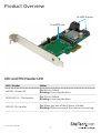
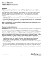
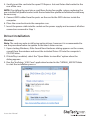
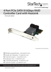
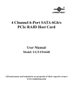
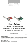
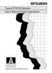
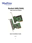
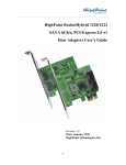
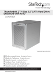
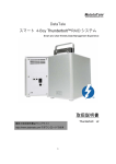
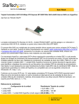
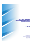
1x mSATA + 3x SATA PCIe SATA III 6Gbps
RAID Controller Card
PEXMSATA343
*actual product may vary from photos
DE: Bedienungsanleitung - de.startech.com
FR: Guide de l'utilisateur - fr.startech.com
ES: Guía del usuario - es.startech.com
IT: Guida per l'uso - it.startech.com
NL: Gebruiksaanwijzing - nl.startech.com
PT: Guia do usuário - pt.startech.com
For the most up-to-date information, please visit: www.startech.com
Manual Revision: 08/13/2014
FCC Compliance Statement
This equipment has been tested and found to comply with the limits for a Class B digital
device, pursuant to part 15 of the FCC Rules. These limits are designed to provide reasonable
protection against harmful interference in a residential installation. This equipment generates,
uses and can radiate radio frequency energy and, if not installed and used in accordance with
the instructions, may cause harmful interference to radio communications. However, there
is no guarantee that interference will not occur in a particular installation. If this equipment
does cause harmful interference to radio or television reception, which can be determined by
turning the equipment off and on, the user is encouraged to try to correct the interference by
one or more of the following measures:
• Reorient or relocate the receiving antenna.
• Increase the separation between the equipment and receiver.
• Connect the equipment into an outlet on a circuit different from that to which the receiver
is connected.
• Consult the dealer or an experienced radio/TV technician for help.
Use of Trademarks, Registered Trademarks, and other Protected Names and Symbols
This manual may make reference to trademarks, registered trademarks, and other
protected names and/or symbols of third-party companies not related in any way to
StarTech.com. Where they occur these references are for illustrative purposes only and do not
represent an endorsement of a product or service by StarTech.com, or an endorsement of the
product(s) to which this manual applies by the third-party company in question. Regardless
of any direct acknowledgement elsewhere in the body of this document, StarTech.com hereby
acknowledges that all trademarks, registered trademarks, service marks, and other protected
names and/or symbols contained in this manual and related documents are the property of
their respective holders.
Instruction Manual
Product Overview
3x SATA III ports
1x mSATA slot
LED and PIN Header LED
LED / Header
Status
mSATA - Green LED
On: Drive is linked
Blinking: Accessing the drive
SATA LED 0-3 - Pin Headers
On: Drive is linked
Blinking: Accessing the drive
LED All - Pin Header
On: When any one of the 4 drives is linked
Blinking: When any one of the 4 drives is accessing
Instruction Manual
1
Installation
mSATA SSD Installation
WARNING!
SSD Drives and storage adapters require careful handling. If you are not careful
with your SSD Drive, lost data may result. Always handle your drive with caution. Be
sure that you are properly grounded by wearing an anti-static strap when handling
computer components or discharge yourself of any static electricity build-up by
touching a large grounded metal surface (such as the computer case) for several
seconds.
1. Slide the mSATA connector on your SSD into the mSATA reciprocal connector on the
PEXMSATA343
2. Gently press the drive down toward the metal mounting bracket clip, until the drive
clicks into place. The SSD has now been installed.
Note: To remove your SSD pull upward on the metal tabs located near the top of the
drive, then slide the drive out.
Hardware Installation
WARNING! PCI Express cards, like all computer equipment, can be severely damaged
by static electricity. Be sure that you are properly grounded before opening your
computer case or touching your PCI Express card. StarTech.com recommends that you
wear an anti-static strap when installing any computer component. If an anti-static
strap is unavailable, discharge yourself of any static electricity build-up by touching a
large grounded metal surface (such as the computer case) for several seconds. Also be
careful to handle the PCI Express card by its edges and not the gold connectors.
1. Turn your computer off and any peripherals connected to the computer (i.e. Printers,
external hard drives, etc.). Unplug the power cable from the rear of the power
supply on the back of the computer and disconnect all peripheral devices.
2. Remove the cover from the computer case. See documentation for your computer
system for details.
3. Locate an open PCI Express x2 slot and remove the metal cover plate on the rear of
the computer case (Refer to documentation for your computer system for details).
NOTE: This card will work in PCI Express slots of additional lanes (i.e.x4, x8, or x16 slots).
Instruction Manual
2
4. Gently insert the card into the open PCI Express slot and fasten the bracket to the
rear of the case.
NOTE: If installing the card into a small form factor/low profile system, replacing the
pre-installed full profile bracket with the included low profile installation bracket may
be necessary.
5. Connect SATA cables from the ports on the card to the SATA devices inside the
computer.
6. Place the cover back onto the computer case.
7. Insert the power cable into the socket on the power supply and reconnect all other
connectors removed in Step 1.
Driver Installation
Windows
Note: The card may auto-install using native drivers, however it is recommended to
use the procedure below to update to the latest driver version.
1. Upon starting Windows, if the Found New Hardware dialog appears on the screen,
cancel/close the window and insert the included Driver CD into the computer’s
CD/DVD drive.
2. If AutoPlay is enabled, select the “Open folder to view files” option when the
dialog appears.
3. Run the “drvSetup_V1057.exe” application located in the “SATA6G_M9128” folder
to start the installation process.
Instruction Manual
3
4. If AutoPlay is disabled, browse to your CD/DVD drive and open the “drvSetup_
V1057.exe” application located in the “SATA6G_M9128” folder to start the installation
process.
5. Follow any on-screen instructions to complete the software installation.
Note: You may be prompted to restart your system.
Management Utility Installation
RAID and/or HyperDuo configuration can be accomplished either through the
integrated card-BIOS utility, or through the Marvell Storage Utility (MSU). Details for
installing the MSU are below.
To install the Marvell Storage Utility (MSU) in Windows:
1. Run the “MSUSetup.exe” application located in the “SATA6G_M9128\GUI” folder and
follow the on-screen instructions. Select “Next” and accept the license agreement
when prompted – the default installation options are recommended.
2. After installing the Apache2 HTTP Server (which is a built-in component of the
installation package), the installation may trigger a Windows Security Alert on some
versions of Windows, please allow access.
Instruction Manual
4
3. Before opening the MSU, verify that Active Scripting or JavaScript is enabled in
the browser.
a. Internet Explorer
i. From the menu bar, select Tools > Internet Options.
ii. Select the “Security” tab, then “Local Intranet”, then “Custom level”.
iii. In the list of settings, scroll down to Scripting > Active scripting.
iv. Select “Enable”, then click “OK” to confirm the selection.
b. Firefox
i. From the menu bar, select Tools > Options
ii. Select the “Content” tab and ensure that the “Enable Javascript” option is
checked (should be by default) – if it is not, select it and click “OK”
Instruction Manual
5
Verifying Installation
Windows
1. From the main desktop or start menu, right-click on “Computer” (“My Computer” in
XP), then select “Manage.”
2. In the new Computer Management window, select Device Manager from the left
window panel.
Instruction Manual
6
3. Under the “Storage Controllers” category (“SCSI and RAID Controllers” in XP) should
be a “Marvell 92xx” device. Right-click on the device and select “Properties” to make
sure it is installed and working correctly.
Note: After a successful installation, some users may notice a yellow icon next to
“Marvell Console ATA Device” under the “Other Devices” category within the Device
Manager. Device performance and operation is not affected by this notification. If you
wish to remove this to icon, run the “drv Setup _V 1017.exe” application located in the
“SATA6G_M9128” folder.
Hard Drive Initialization
If the mSATA SSD or SATA HDD is new or otherwise blank, it may need to be initialized
and formatted before use. Follow the steps below in a Windows interface to initialize
the drive.
1. From the main desktop or start menu, right-click on “Computer” (“My Computer” in
XP), then select “Manage.”
2. In the new Computer Management window, select Disk Management from the left
window panel.
3. A dialog window should automatically appear, asking you to initialize the drive.
Depending on the version of Windows, it will give you the option of either creating
an “MBR” or “GPT” disk. GPT (GUID partition) is not compatible with some older
operating systems, while MBR is supported by newer and older operating systems.
4. Once initialized, locate the Disk that says it is “Unallocated” (check the listed hard
drive capacity to confirm it’s the correct hard drive) and then right-click in the
section that says “Unallocated” and select “New Simple Volume” (“New Partition”
in XP).
Instruction Manual
7
5. Follow the on-screen prompts to initialize the drive in the format of your choice.
Port Multiplier
Port Multiplier (PM) allows for multiple SATA drives (up to 4) to be connected to a
single SATA host port. PM allows for easy, cost-effective storage scalability both inside
and outside the PC or server. It is commonly used to connect a multi-drive SATA/eSATA
hard drive enclosure/backplane using a single cable. This greatly expands the storage
capabilities of the SATA controller beyond its normal port count. Please visit StarTech.
com for more SATA controllers that support the Port Multiplier feature.
Note: Only the three SATA ports can use the Port Multiplier feature. Only one of these
SATA ports can use the Port Multiplier feature at a time. The card supports up to 4
drives connected via Port Multiplier, and 7 drives total (including a mSATA SSD).
Mac OS does not support Port Multiplier.
Instruction Manual
8
Operation
RAID Configuration
Card BIOS Method
WARNING! Creating a RAID virtual disk destroys all data on the physical disks included
in the virtual disk set. Make sure to back up all data before continuing.
1. When prompted on startup, press Ctrl+M to enter the card BIOS utility
Press <Ctrl>+<M> to enter BIOS Setup or <Space> to continue_
2. Using the arrow keys to navigate, move to “HBA0: Marvell 0” and press Enter to
select
3. Press Enter again to open the Configuration Wizard
4. Use the arrow keys to scroll through the list of free physical disks to select the drives
that will be part of the RAID set. Press Space to select/de-select a disk.
NOTE: When a disk is selected, an asterisk (*) appears to the left of the disk label.
5. After selecting the required disks, press Enter to continue.
Instruction Manual
9
1. The “Create Virtual Disk” configuration options appear in the “Information” pane
(right-side), here you are able to select the RAID level and other
configuration options:
a. Select 2 HDDs for RAID 0 or RAID 1
b. Select 3 HDDs for RAID 0
c. Select 4 HDDs for RAID 0 or RAID 10
2. After configuring the virtual disk, highlight “Next” and press Enter. Press Y to confirm
the creation of the virtual disk. It will now be listed in the Topology Pane (left).
Administration Console Method
WARNING! Creating a RAID virtual disk destroys all data on the physical disks included
in the virtual disk set. Make sure to back up all data before continuing.
1. From the left pane of main screen of the Marvell Storage Utility (MSU), select the
adapter and hover the mouse over the “Operation” tab.
2. Select “Create RAID”
Instruction Manual
10
3. From the “Create new VD” screen that appears, click the “Select RAID Level” dropdown to choose the appropriate RAID type
4. This will enable you to place a checkbox beside the disks that you would like to use
as part of the RAID set. Once you have selected, click “Next” to confirm
your selection.
5. You will now be presented with configuration options for your RAID set. Choose the
appropriate options and select “Submit” to confirm your changes. Your virtual disk
will then be visible in the left pane – the same properties can be accessed later by
selecting your virtual disk from the left pane.
HyperDuo Configuration
HyperDuo offers the following two modes that you can configure using either of the
procedures outlined in the following sections:
• Safe mode creates a virtual disk that is optimized for best fault tolerance – the
frequently accessed files copied to the SSD for performance are also stored on the
HDD. It is safe to use with hard drives that contain existing data. Virtual disks created
in safe mode can also be partially rebuilt if the SSD fails, but not if the HDD fails.
• Capacity mode creates a virtual disk that is optimized for maximum utilization of
the SSD – the frequently accessed files are moved to the SSD (not copied). Virtual
disks created in capacity mode have better read and write performance than those
created in safe mode. However, they cannot be rebuilt.
Instruction Manual
11
WARNING! Capacity mode is a data-destructive process. Please back up all data before
using capacity mode.
Card BIOS Method
1. When prompted on startup, press Ctrl+M to enter the card BIOS utility
Press <Ctrl>+<M> to enter BIOS Setup or <Space> to continue_
2. Using the arrow keys to navigate, move to “HBA0: Marvell 0” and press Enter
to select
3. Press Enter again to open the Configuration Wizard
4. Use the arrow keys to scroll through the list of free physical disks to select the drives
that will be part of the HyperDuo set. Press Space to select/de-select a disk.
NOTE: When a disk is selected, an asterisk (*) appears to the left of the disk label.
5. After selecting the required disks, press Enter to continue.
6. The “Create Virtual Disk” configuration options appear in the “Information” pane
(right-side), here you are able to select HyperDuo or RAID options
NOTE: The default HyperDuo mode is Safe mode.
Instruction Manual
12
7. Highlight “Keep original data” and press Enter to select. Select Yes or No and
press Enter.
WARNING! Selecting “No” will destroy all data on the disks included in the virtual
disk set. Make sure to back up all data before continuing. The “Keep original data”
option is disabled when you choose Capacity mode, as it is inherently datadestructive.
8. After configuring the virtual disk, highlight “Next” and press Enter. Press Y to confirm
the creation of the virtual disk. It will now be listed in the Topology Pane (left).
Administration Console Method
1. From the left pane of main screen of the Marvell Storage Utility (MSU), select the
adapter and hover the mouse over the “Operation” tab.
2. Select “Create HyperDuo”
3. Select either Safe mode or Capacity mode from the drop-down in the right pane.
Click the “Submit” button once you have selected the appropriate options for
your operation.
NOTE: If Safe mode is selected, you will have the option to select the checkbox
marked “Keep Original Data” – this option is NOT available in Capacity mode, as it is
inherently data-destructive.
Instruction Manual
13
The newly created HyperDuo drive will then appear in the left pane and begin
initializing. This can take up to 30 minutes to complete, and system performance may
be slow during this period.
HyperDuo Management
1. From the left pane of the MSU, select “HyperDuo Service”
2. The right pane will then display available programs and folder that you can
customize to one of the following optimization modes:
a. Check Auto to have the MSU manage the optimization of a folder or program
automatically.
b. Check Cache to manually select a folder or program for optimization.
c. Check neither to specify that a folder or program should never be optimized.
Instruction Manual
14
3. Select Submit to apply your changes, then select “OK” on the pop-up that follows.
4. If the folder you would like to optimize is not available, select “Advanced” from the
“HyperDuo Service” pane.
5. The “Customize Wizard” will pop-up and allow you to select the desired folders.
Instruction Manual
15
Specifications
PCI Express 2.0
Host Interface
SATA Revision 3.0
Card Profile
Standard Profile (LP bracket incl.)
Chipset ID
Marvell 9230
3x 7-pin SATA plug
Internal Connectors
1x 52 pin mSATA slot
Maximum Transfer Rate
SATA: 6Gbps
RAID Support
RAID 0, 1, 1+0
Port Multiplier
Yes
Operating Temperature
5°C to 50°C (41°F to 122°F)
Storage Temperature
-25°C to 70°C (-13°F to 158°F)
Humidity
20-80% RH
Dimensions (LxWxH)
115mm x 20mm x 120mm
Weight
55g
Compatible Operating Systems
Windows® 8.1 (32/64bit), 8 (32/64bit), 7
(32/64), Vista (32/64), XP (32/64), Windows®
Server 2012, 2008 R2, 2003, Mac OS 10.6
and up (Tested up to 10.9), Linux®
*Port Multiplier is not supported in Mac OS
Instruction Manual
16
Technical Support
StarTech.com’s lifetime technical support is an integral part of our commitment to
provide industry-leading solutions. If you ever need help with your product, visit
www.startech.com/support and access our comprehensive selection of online tools,
documentation, and downloads.
For the latest drivers/software, please visit www.startech.com/downloads
Warranty Information
This product is backed by a two year warranty.
In addition, StarTech.com warrants its products against defects in materials
and workmanship for the periods noted, following the initial date of purchase.
During this period, the products may be returned for repair, or replacement with
equivalent products at our discretion. The warranty covers parts and labor costs only.
StarTech.com does not warrant its products from defects or damages arising from
misuse, abuse, alteration, or normal wear and tear.
Limitation of Liability
In no event shall the liability of StarTech.com Ltd. and StarTech.com USA LLP (or their
officers, directors, employees or agents) for any damages (whether direct or indirect,
special, punitive, incidental, consequential, or otherwise), loss of profits, loss of business,
or any pecuniary loss, arising out of or related to the use of the product exceed the
actual price paid for the product. Some states do not allow the exclusion or limitation
of incidental or consequential damages. If such laws apply, the limitations or exclusions
contained in this statement may not apply to you.
Instruction Manual
17
Hard-to-find made easy. At StarTech.com, that isn’t a slogan. It’s a promise.
StarTech.com is your one-stop source for every connectivity part you need. From
the latest technology to legacy products — and all the parts that bridge the old and
new — we can help you find the parts that connect your solutions.
We make it easy to locate the parts, and we quickly deliver them wherever they need
to go. Just talk to one of our tech advisors or visit our website. You’ll be connected to
the products you need in no time.
Visit www.startech.com for complete information on all StarTech.com products and
to access exclusive resources and time-saving tools.
StarTech.com is an ISO 9001 Registered manufacturer of connectivity and technology
parts. StarTech.com was founded in 1985 and has operations in the United States,
Canada, the United Kingdom and Taiwan servicing a worldwide market.