1
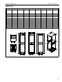
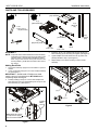
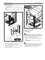
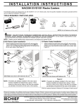
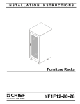
INSTALLATION INSTRUCTIONS
Knockdown Racks
Spanish Product Description
German Product Description
Portuguese Product Description
Italian Product Description
Dutch Product Description
French Product Description
NS1F12-20-28-36-41
NS1F12-20-28-36-41
Installation Instructions
DISCLAIMER
Milestone AV Technologies and its affiliated corporations and
subsidiaries (collectively "Milestone"), intend to make this
manual accurate and complete. However, Milestone makes no
claim that the information contained herein covers all details,
conditions or variations, nor does it provide for every possible
contingency in connection with the installation or use of this
product. The information contained in this document is subject
to change without notice or obligation of any kind. Milestone
makes no representation of warranty, expressed or implied,
regarding the information contained herein. Milestone assumes
no responsibility for accuracy, completeness or sufficiency of
the information contained in this document.
Chief® is a registered trademark of Milestone AV Technologies.
All rights reserved.
IMPORTANT WARNINGS AND
CAUTIONS!
WARNING: Failure to read, thoroughly understand, and
follow all instructions can result in serious personal injury,
damage to equipment, or voiding of factory warranty! It is the
installer’s responsibility to make sure all components are
properly assembled and installed using the instructions
provided.
WARNING: Exceeding the weight capacity can result in
serious personal injury or damage to equipment! It is the
installer’s responsibility to make sure the combined weight of
all components located within the rack does not exceed
500 lbs (226.8 kg). Use with products heavier than the
maximum weight indicated may result in instability or collapse
of the rack causing possible injury.
IMPORTANT ! : Minimum spacings between the Accessories
and components and the (ITC/AV) Rack Enclosure shall be
maintained for safe operation of the equipment when installed
in accordance with the National Electric Code, ANSI/NFPA 702008. Operating temperature inside rack shall not exceed
104° F.
WARNING: A WARNING alerts you to the possibility of
serious injury or death if you do not follow the instructions.
CAUTION: A CAUTION alerts you to the possibility of
damage or destruction of equipment if you do not follow the
corresponding instructions.
LEGEND
2
Tighten Fastener
Open-Ended Wrench
Apretar elemento de fijación
Llave de boca
Befestigungsteil festziehen
Gabelschlüssel
Apertar fixador
Chave de bocas
Serrare il fissaggio
Chiave a punte aperte
Bevestiging vastdraaien
Steeksleutel
Serrez les fixations
Clé à fourche
Loosen Fastener
Phillips Screwdriver
Aflojar elemento de fijación
Destornillador Phillips
Befestigungsteil lösen
Kreuzschlitzschraubendreher
Desapertar fixador
Chave de fendas Phillips
Allentare il fissaggio
Cacciavite a stella
Bevestiging losdraaien
Kruiskopschroevendraaier
Desserrez les fixations
Tournevis à pointe cruciforme
Installation Instructions
NS1F12-20-28-36-41
DIMENSIONS
MODEL
WEIGHT
CAPACITY LBS
(KG)
RACKING
HEIGHT UNITS
OVERALL DEPTH
(A) IN (MM)
USABLE DEPTH
(B) IN (MM)
WIDTH (C)
IN (MM)
HEIGHT (D)
IN (MM)
HEIGHT
W/CASTERS (E)
IN (MM)
HEIGHT W/MIN.
LEVELER (F)
IN (MM)
NS1F1223
500 LBS (226.8)
12
23 (584.2)
22.6 (574.0)
19.25 (489.0)
28.4 (720.3)
29.2 (742.4)
29.1 (741.7)
NS1F2023
500 LBS (226.8)
20
23 (584.2)
22.6 (574.0)
19.25 (489.0)
42.4 (1077)
43.2 (1097.3)
43.1 (1094.7)
NS1F2823
500 LBS (226.8)
28
23 (584.2)
22.6 (574.0)
19.25 (489.0)
56.4 (1432.6)
57.2 (1452.9)
57.1(1450.3)
NS1F3623
500 LBS (226.8)
36
23 (584.2)
22.6 (574.0)
19.25 (489.0)
70.4 (1788.2)
71.2 (1808.5)
71.1 (1805.9)
NS1F4123
500 LBS (226.8)
41
23 (584.2)
22.6 (574.0)
19.25 (489.0)
84.4 (2143.8)
85.2 (2164.1)
85.1 (2161.5)
NS1F1228
500 LBS (226.8)
12
28 (711.2)
27.6 (701.0)
19.25 (489.0)
28.4 (720.3)
29.2 (742.4)
29.1 (741.7)
NS1F2028
500 LBS (226.8)
20
28 (711.2)
27.6 (701.0)
19.25 (489.0)
42.4 (1077)
43.2 (1097.3)
43.1 (1094.7)
NS1F2828
500 LBS (226.8)
28
28 (711.2)
27.6 (701.0)
19.25 (489.0)
56.4 (1432.6)
57.2 (1452.9)
57.1(1450.3)
NS1F3628
500 LBS (226.8)
36
28 (711.2)
27.6 (701.0)
19.25 (489.0)
70.4 (1788.2)
71.2 (1808.5)
71.1 (1805.9)
NS1F4128
500 LBS (226.8)
41
28 (711.2)
27.6 (701.0)
19.25 (489.0)
84.4 (2143.8)
85.2 (2164.1)
85.1 (2161.5)
3
NS1F12-20-28-36-41
Installation Instructions
PARTS AND TOOLS REQUIRED
B (1)
[Top assembly]
A (1)
[Base assembly]
C (2)
[Rack rail,
left]
• 7/16"
• 13mm (use to
adjust levelers)
D (2)
[Rack rail,
right]
E (2)
[Cross brace]
F (2)
[Alignment panel]
#2
G (24)
10-32 x 3/4"
ASSEMBLY
4.
Install two 10-32 x 3/4" Phillips head screws (G) through
base assembly (A) into rack rail (C) and tighten. (See Figure 2)
5.
Tighten Phillips truss head machine screw (H) which was
partially installed in Step 3. (See Figure 2)
6.
Repeat Steps 2-5 for three remaining corners of base
assembly.
NOTE: If optional casters will be added to the base assembly,
install them now following instructions included with the
optional casters. Leave levelers installed and adjust
them using a 13mm wrench so they are as close to the
floor as possible, yet still allow movement of the rack on
the casters.
J (18)
1/4-20
H (22)
1/4-20 x 5/8"
Adding Rack Rails
1.
2.
Place base assembly upright onto foot levelers or optional
casters.
Lower one left rack rail (C) into one corner of base assembly
(A). (See Figure 1)
IMPORTANT ! : Partial install of Phillips truss head
machine screw (H) should be done BY HAND before
completing Steps 4 through 6.
3.
(C)
Partially install (by hand) one 1/4-20 x 5/8" Phillips truss
head machine screw (H) (approximately five turns) into the
base assembly (A). (See Figure 1)
2
(A)
(D)
1
L
FR
T
ON
5
(C)
Indicates
LEFT
rack rail
(A)
3
(H) x 1
NOTE: Rack rail indicator
(L or R) must be upright
when rack rail is installed.
Figure 1
4
(H) x 1
4
Figure 2
(G) x 2
Installation Instructions
NS1F12-20-28-36-41
Attaching Top Assembly
1.
2.
3.
Place top assembly (B) onto the four installed rack rails.
(See Figure 3)
Insert and tighten two 10-32 x 3/4" Phillips head screws (G)
through top assembly (B) into rack rail. (See Figure 3)
(H) x 4
2
Insert two 1/4-20 x 5/8" Phillips truss head machine screws
(H) through top assembly (B) and rail rack, into two
1/4-20 keps nuts (J). (See Figure 3)
(E)
(J) x 4
(E)
(B)
(J) x 2
(H) x 2
3
(J) x 4
FR
O
(C)
NT
1
(H) x 4
Figure 4
Attaching Alignment Panels
FR
ON
T
1.
Vertically center the alignment panel (F) on the rack rails,
and attach using four 10-32 x 3/4" Phillips head screws (G).
(See Figure 5)
2.
Repeat for back of S1 rack. (See Figure 5)
(D)
2
(G) x 2
2
(G) x 4
Figure 3
CAUTION: Install alignment panels and cross braces,
VERTICALLY CENTERED on the rack rails, BEFORE
loading components into the rack.
(F)
Attaching Cross Braces
1.
2.
Attach cross brace (E) to side of S1 rack using four
1/4-20 x 5/8" Phillips truss head machine screws (H) with
four 1/4-20 keps nuts (J). (See Figure 4)
Repeat for opposite side of S1 rack. (See Figure 4)
(F)
1
(G) x 4
Figure 5
5
NS1F12-20-28-36-41
Installation Instructions
Attaching Optional Side Panels, Optional Doors
IMPORTANT ! : If installing doors (not included) and side
panels (not included) on an S1 rack, the doors must be
installed before installing the side panels.
1.
If desired, add optional door(s) (not included) to the rack
following instructions included with the door(s).
IMPORTANT ! : If the door(s) are to be attached with the
pull-ring handle on the right side, the grounding screw,
washer and wire already installed on the door must be
removed and reinstalled on the opposite end of the door
before the door is installed. See instructions included
with the door(s).
2.
If desired, add optional side panels (not included) to the
rack following instructions included with the panel(s).
Locations of
grounding lugs
NOTE: If NOT adding door(s), proceed to Step 4 of
Completing Installation section.
(front view of rack)
Figure 7
DANGER: IMPROPER WIRING CAN LEAD TO DEATH
OR SEVERE PERSONAL INJURY! Grounding must be
installed by qualified personnel using a UL Recognized No.
12AWG Green and Yellow grounding wire connected to
grounding lug on rack.
Grounding screw and nut
installed at factory
Earthing symbol IEC 60417 No. 5019
affixed adjacent to grounding terminal.
Figure 6
6
Installation Instructions
NS1F12-20-28-36-41
Completing Installation
1.
Remove and save 1/4" nut from the grounding lug on rack
rail. (See Figure 8)
2.
Attach grounding wire from door to the grounding lug. (See
Figure 8)
3.
Replace and tighten nut onto grounding lug. (See Figure 8)
6
4
logo panel
(front view of rack)
Figure 9
LOADING THE RACK
Load Distribution
CAUTION: BEGIN PLACEMENT OF LOAD AT BOTTOM
OF RACK! Load rack, moving from bottom toward top of rack.
Loading rack incorrectly may result in instability causing
possibly injury and/or damage to components.
Add grounding wire
1
1.
Begin placement of components into the rack at the lowest
point.
2.
Continue placing items into the rack, moving from the
bottom upward.
3
Figure 8
4.
Change optional logo panel by removing and saving 4 nuts
from studs at inside top of front. (See Figure 9)
5.
Remove blank panel and replace with optional personalized
logo panel. (See Figure 9)
6.
Replace and tighten four nuts removed in Step 4.
CAUTION: DISTRIBUTE LOAD CORRECTLY! Load rack
with 2/3 total weight of components in the lower half of rack.
Loading rack incorrectly may result in instability causing
possible injury and/or damage to components.
7
NS1F12-20-28-36-41
Installation Instructions
USA/International
Europe
Chief Manufacturing, a products division
of Milestone AV Technologies
8800-002167 Rev00
2012 Milestone AV Technologies, a
Duchossois Group Company
www.chiefmfg.com
04/12
Asia Pacific
A
P
F
A
P
F
A
6436 City West Parkway, Eden Prairie, MN 55344
800.582.6480 / 952.225.6000
877.894.6918 / 952.894.6918
Franklinstraat 14, 6003 DK Weert, Netherlands
+31 (0) 495 580 852
+31 (0) 495 580 845
Office No. 1 on 12/F, Shatin Galleria
18-24 Shan Mei Street
Fotan, Shatin, Hong Kong
P 852 2145 4099
F 852 2145 4477