1
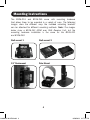
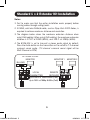
pr ch re R W
a
od an gis e
uc ce te gi rr
t— to r o st an
ww w nlin ra ty
w. in a e ti
t
tri
o
p p F R o da n
lit EE y f :
e . T or
co rip a
m p
/w Li
ar te
ra
nt
y
Owner’s Manual
HDMI Over Cat5
1x2 Extenders
Models: B126-2A1, B126-2A0
Package Contents 2
Product Features 2
Mounting Instructions 4
Standard 1 x 2 Extender Kit Installation 5
1 x 2 Extender Kit with Remote/Repeater Installation 7
Standard Extender/Splitter Installation 10
Extender/Splitter with Remote/Repeater Installation 13
Troubleshooting 17
Warranty & Warranty Registration 19
13-08-043 93-32D0.indd 1
1111 W. 35th Street, Chicago, IL 60609 USA
www.tripplite.com/support
Copyright © 2013 Tripp Lite. All rights reserved.
8/28/2013 2:17:35 PM
Package Contents
• B126-2A1 Kit or B126-2A0 Receiver Unit
• External Power Supply
(Input: 100-240V, 50/60Hz, 0.5A Output: 5V, 2A)
• Mounting Hardware
• Screwdriver for Equalization Adjustment
• Owner’s Manual
Product Features
• Extends an HDMI signal to 2 monitors up to 200 ft. from the source
over a single Cat5e/6 cable.
• A B126-002 or B126-004 extender/splitter transmitter unit is required
for use with the B126-1A0 1x2 receiver unit.
• Extends a 1080p (60Hz) signal up to 150 ft. from the source using
Cat6 cabling, or up to 125 ft. using Cat5 cabling.
• Extends a 1080i (60Hz) signal up to 200 ft. from the source using
Cat6 cabling, or up to 175 ft. using Cat5 cabling.
• Use 24 AWG, solid wire Cat5e/6 cable, such as Tripp Lite’s N202-Series,
to achieve maximum distance and resolution.
• Further expand the range and number of monitors by adding B126-110
repeater units.
• Add up to three repeaters on each Cat5e/6 channel, for a total of 4
displays per channel (An Active remote receiver should be the last unit
in a channel).
• A 1080p (60Hz) signal can be extended up to 125 ft. for each repeater
added into a channel (or up to 175 ft, for a 1080i (60Hz) signal when
using either Cat5e or Cat6 cabling).
• Supports 24-bit True Color (8-bits per channel).
• Built-in equalization control to adjust the video image.
13-08-043 93-32D0.indd 2
2
8/28/2013 2:17:35 PM
Product Features
• Supports both stereo and 7.1-channel surround sound audio
(7.1-channel surround sound signal will be Multi-Channel or PCM).
• HDCP and 3D compatible.
• Plug and play; No software or drivers required.
• Compatible with all operating systems.
• Mounting hardware included.
Optional Accessories:
• B126-110 – Remote Repeater Unit
• N202-Series Cat6 24 AWG, Solid Wire Patch Cables
• P568-Series High-Speed HDMI Cables
13-08-043 93-32D0.indd 3
3
8/28/2013 2:17:35 PM
Mounting Instructions
The B126-2A1 and B126-2A0 come with mounting hardware
that allows them to be mounted in a variety of ways. The following
images show the different ways the included mounting brackets
can be attached for different mounting methods. Note: The images
below show a B126-1A1 HDMI over Cat5 Receiver Unit, but the
mounting hardware installation is the same for the B126-2A1
and B126-2A0.
Wall-mount 1
Wall-mount 2
19” Rackmount
Pole Mount
13-08-043 93-32D0.indd 4
4
8/28/2013 2:17:37 PM
Standard 1 x 2 Extender Kit Installation
Notes:
1.Test to make sure that the entire installation works properly before
running cables through ceilings/walls.
2.24 AWG, solid wire Cat5e/6 cable, such as Tripp Lite’s N202-Series, is
required to achieve maximum distance and resolution.
3.The diagram below shows the maximum extension distance when
using Cat6 cabling. When using Cat5 cabling, the maximum extension
distance is 175 ft. at 1080i (60Hz), and 125 ft. at 1080p (60Hz).
4.The B126-2A1 is set to transmit a stereo audio signal by default.
Press the Audio button on the transmitter unit to switch to 7.1-channel
surround sound audio. (7.1-channel surround sound signal will be
Multi-Channel or PCM)
OPTIONAL LOCAL
MONITOR
MONITOR 1
MONITOR 2
BLU-RAY
13-08-043 93-32D0.indd 5
LOCAL
REMOTE
TRANSMITTER
RECEIVER
Up to 200 ft. at 1080i @ 60Hz (Cat6)
Up to 150 ft. at 1080p @ 60Hz (Cat6)
5
8/28/2013 2:17:38 PM
Standard 1 x 2 Extender Kit Installation
1 Make sure all devices being connected are powered OFF.
2 Connect the HDMI source to the INPUT port on the transmitter unit
using a Tripp Lite P568-Series High-Speed HDMI Cable.
3 Optional: Connect a monitor to the LOCAL port on the transmitter
unit using a Tripp Lite P568-Series High-Speed HDMI Cable.
4 Connect the external power supply to the transmitter unit and plug the
transmitter unit into a Tripp Lite Surge Suppressor, Power Distribution
Unit (PDU), or Uninterruptible Power Supply (UPS). The green RJ45 LED
illuminates to indicate that the unit is receiving power from the external
power supply.
5 Using Cat5e/6 cable, connect the RJ45 port on the transmitter unit
marked OUTPUT to the RJ45 port on the receiver unit marked INPUT.
6 Connect the external power supply to the receiver unit and plug the
receiver unit into a Tripp Lite Surge Suppressor, Power Distribution Unit
(PDU), or Uninterruptible Power Supply (UPS). The green RJ45 LED
illuminates to indicate that the unit is receiving power from the external
power supply.
7 Connect a monitor to the OUTPUT 1 port on the receiver unit using a
Tripp Lite P568-Series High-Speed HDMI cable.
8 Repeat step 7 for the OUTPUT 2 port on the receiver unit.
9 Turn on the power to the connected devices. The orange RJ45 LED’s
on the transmitter and receiver units illuminate to indicate that a
signal is being received from the HDMI source. The video image will
now be displayed on the connected monitors.
10 If necessary, use the Equalization control on the receiver unit to adjust
the video image. Note: An improper Equalization setting can cause
the monitor not to display an image at all. Try each setting until an
acceptable image is displayed.
13-08-043 93-32D0.indd 6
6
8/28/2013 2:17:38 PM
1 x 2 Extender Kit with
Remote/Repeater Installation
Notes:
1.Test to make sure that the entire installation works properly before
running cables through ceilings/walls.
2.The diagram below shows the maximum extension distance when using
either Cat5e or Cat6 cabling. 24 AWG, solid wire Cat5e/6 cable, such
as Tripp Lite’s N202-Series, is required to achieve maximum distance
and resolution.
3.The B126-2A1 is set to transmit a stereo audio signal by default.
Press the Audio button on the transmitter unit to switch to 7.1-channel
surround sound audio. (7.1-channel surround sound signal will be
Multi-Channel or PCM)
OPTIONAL LOCAL
MONITOR
Up to 175 ft. at 1080i (60Hz)
Up to 125 ft. at 1080p (60Hz)
Up to 175 ft. at 1080i (60Hz)
Up to 125 ft. at 1080p (60Hz)
Up to 175 ft. at 1080i (60Hz)
Up to 125 ft. at 1080p (60Hz)
BLU-RAY
B126-2A1 LOCAL
TRANSMITTER
Up to 175 ft. at 1080i (60Hz)
Up to 125 ft. at 1080p (60Hz)
MONITOR 1 MONITOR 2
B126-2A1 REMOTE
RECEIVER
B126-110 REMOTE
REPEATER
B126-110 REMOTE
REPEATER
B126-110 REMOTE
REPEATER
1 Make sure all devices being connected are powered OFF.
2 Connect the HDMI source to the INPUT port on the transmitter unit
using a Tripp Lite P568-Series High-Speed HDMI Cable.
3 Optional: Connect a monitor to the LOCAL port on the transmitter
unit using a Tripp Lite P568-Series High-Speed HDMI Cable.
13-08-043 93-32D0.indd 7
7
8/28/2013 2:17:39 PM
1 x 2 Extender Kit with
Remote/Repeater Installation
4 Connect the external power supply to the transmitter unit and plug the
transmitter unit into a Tripp Lite Surge Suppressor, Power Distribution
Unit (PDU), or Uninterruptible Power Supply (UPS). The green RJ45 LED
illuminates to indicate that the unit is receiving power from the external
power supply.
5 Using Cat5e/6 cable, connect the RJ45 port on the transmitter unit
marked OUTPUT to the RJ45 port on the B126-110 repeater unit
marked INPUT.
6 Connect a monitor to the HDMI OUTPUT port on the repeater unit
using a Tripp Lite P568-Series High-Speed HDMI Cable.
7 Connect the external power supply to the repeater unit and plug the
repeater unit into a Tripp Lite Surge Suppressor, Power Distribution
Unit (PDU), or Uninterruptible Power Supply (UPS). The green power
and the green RJ45 LEDs will illuminate to indicate that the unit is
receiving power from the external power supply.
Up to 4 units can be daisy-chained (3 repeaters and 1 active receiver). To
add additional repeater units, proceed to step 8. To finish your installation
with the B126-2A1 receiver unit, proceed to step 11.
8 Using Cat5e/6 cable, connect the RJ45 port on the repeater unit marked
OUTPUT to the RJ45 port on a second repeater unit marked INPUT.
9 Connect a monitor to the HDMI OUTPUT port on the repeater unit
using a Tripp Lite P568-Series High-Speed HDMI Cable.
10 Connect the external power supply to the repeater unit and plug the
repeater unit into a Tripp Lite Surge Suppressor, Power Distribution
Unit (PDU), or Uninterruptible Power Supply (UPS). The green power
and the green RJ45 LEDs will illuminate to indicate that the unit is
receiving power from the external power supply.
13-08-043 93-32D0.indd 8
8
8/28/2013 2:17:39 PM
1 x 2 Extender Kit with
Remote/Repeater Installation
To add a third remote/repeater unit, repeat steps 8 through 10. To finish
your installation with the B126-2A1 receiver unit, proceed to step 11.
11 Using Cat5e/6 cable, connect the RJ45 port on the repeater unit
marked OUTPUT to the RJ45 port on the receiver unit marked INPUT.
12 Connect a monitor to the OUTPUT 1 port on the receiver unit using a
Tripp Lite P568-Series High-Speed HDMI cable.
13 Repeat step 12 for the OUTPUT 2 port on the receiver unit.
14 Connect the external power supply to the receiver unit and plug the
receiver unit into a Tripp Lite Surge Suppressor, Power Distribution
Unit (PDU), or Uninterruptible Power Supply (UPS). The green RJ45
LED illuminates to indicate that it is receiving power from the external
power supply.
15 Turn on the power to the connected devices. The orange RJ45 LEDs
on all units will illuminate to indicate that a signal is being received
from the HDMI source. The video image will now be displayed on the
connected monitors.
16 If necessary, use the Equalization control on the repeater and receiver
units to adjust the video image. Note: An improper Equalization
setting can cause the monitor not to display an image at all. Try each
setting until an acceptable image is displayed.
13-08-043 93-32D0.indd 9
9
8/28/2013 2:17:40 PM
Standard Extender/Splitter Installation
Notes:
1.Test to make sure that the entire installation works properly before
running cables through ceilings/walls.
2.24 AWG, Solid Wire Cat5e/6 cable, such as Tripp Lite’s N202-Series,
is required to achieve maximum distance and resolution.
3.The diagram below shows the maximum extension distance when
using Cat6 cabling. When using Cat5 cabling, the maximum extension
distance is 175 ft. at 1080i (60Hz), and 125 ft. at 1080p (60Hz).
4.The B126-002 and B126-004 are set to transmit a stereo audio
signal by default. Press the Audio button on the transmitter unit to
switch to 7.1-channel surround sound audio. (7.1-channel surround
sound signal will be Multi-Channel or PCM)
5.The diagram below shows the B126-004 transmitter unit. Installation
is the same for the B126-002, except that there are only two output
ports and no local monitor port.
6.Although the installation instructions below mention the B126-2A0 1x2
receiver unit only, Tripp Lite offers several standard receiver units that
can be used in the event that only one monitor is required on the remote
end: B126-1A0, B126-1A0-WP-1, B126-1P0, and B126-1P0-WP-1.
13-08-043 93-32D0.indd 10
10
8/28/2013 2:17:40 PM
Standard Extender/Splitter Installation
REMOTE UNIT
MODEL: B126-2A0
HDMI OVER Cat5
1 x 2 EXTENDER
B126-2A0
REMOTE UNIT
HDMI OVER Cat5
1 x 2 EXTENDER
REMOTE UNIT
B126-2A0
MODEL: B126-2A0
HDMI OVER Cat5
1 x 2 EXTENDER
B126-2A0
MODEL: B126-2A0
REMOTE UNIT
MODEL: B126-2A0
HDMI OVER Cat5
1 x 2 EXTENDER
Up to 200 ft. at 1080i @ 60Hz (Cat6)
Up to 150 ft. at 1080p @ 60Hz (Cat6)
B126-2A0
B126-004
BLU-RAY
OPTIONAL LOCAL
MONITOR
1 Make sure all devices being connected are powered OFF.
2 Connect the HDMI source to the INPUT port on a B126-002 or
B126-004 transmitter unit using a Tripp Lite P568-Series High-Speed
HDMI Cable.
3 Optional for B126-004: Connect a monitor to the LOCAL port on the
transmitter unit using a Tripp Lite P568-Series High-Speed HDMI Cable.
4 Connect the external power supply to the transmitter unit and plug the
transmitter unit into a Tripp Lite Surge Suppressor, Power Distribution
Unit (PDU), or Uninterruptible Power Supply (UPS). The green RJ45
LEDs on the B126-002 and B126-004, and the red power LED on
the B126-004 will illuminate to indicate that the unit is receiving
power from the external power supply.
5 Using Cat5e/6 cable, connect a RJ45 OUTPUT port on the transmitter
unit to the RJ45 INPUT port on the B126-2A0 1x2 receiver unit.
6 Repeat step 5 to add receiver units to the remaining RJ45 OUTPUT
ports on the transmitter unit.
13-08-043 93-32D0.indd 11
11
8/28/2013 2:17:40 PM
Standard Extender/Splitter Installation
7 Connect the external power supply to the receiver unit and plug the
receiver unit into a Tripp Lite Surge Suppressor, Power Distribution Unit
(PDU), or Uninterruptible Power Supply (UPS). The green RJ45 LED
illuminates to indicate that the unit is receiving power from the external
power supply.
8 Connect a monitor to the OUTPUT 1 port on the receiver unit using a
Tripp Lite P568-Series High-Speed HDMI Cable.
9 Repeat step 8 for the OUTPUT 2 port on the receiver unit.
10 Turn on the power to the connected devices. The orange RJ45 LEDs
on the transmitter and receiver units will illuminate to indicate that
a signal is being received from the HDMI source. The video image
should now be displayed on the connected monitors.
11 If necessary, use the Equalization control on the receiver unit to adjust
the video image. Note: An improper Equalization setting can cause
the monitor not to display an image at all. Try each setting until an
acceptable image is displayed.
13-08-043 93-32D0.indd 12
12
8/28/2013 2:17:40 PM
Extender/Splitter with
Remote/Repeater Installation
Notes:
1.Test to make sure that the entire installation works properly before
running cables through ceilings/walls.
2.The diagram below shows the maximum extension distance when using
either Cat5e or Cat6 cabling. 24 AWG, solid wire Cat5e/6 cable, such
as Tripp Lite’s N202-Series, is required to achieve maximum distance
and resolution.
3.The B126-002 and B126-004 are set to transmit a stereo audio
signal by default. Press the Audio button on the transmitter unit to
switch to 7.1-channel surround sound audio. (7.1-channel surround
sound signal will be Multi-Channel or PCM)
4.The diagram below shows the B126-004 transmitter unit. Installation
is the same for the B126-002, except that there are only two output
ports and no local monitor port.
5.Although the installation instructions below mention the B126-2A0
1x2 receiver unit only, Tripp Lite offers two additional active receivers
that can be used in the event that only one monitor is needed at the
end of a repeater chain: B126-1A0 and B126-1A0-WP-1.
13-08-043 93-32D0.indd 13
13
8/28/2013 2:17:40 PM
Extender/Splitter with
Remote/Repeater Installation
REMOTE UNIT
B126-2A0
REMOTE RECEIVER
B126-110 REMOTE/
REPEATER
B126-110 REMOTE/
REPEATER
B126-110 REMOTE/
REPEATER
B126-2A0
REMOTE RECEIVER
B126-110 REMOTE/
REPEATER
B126-110 REMOTE/
REPEATER
B126-110 REMOTE/
REPEATER
B126-2A0
REMOTE RECEIVER
B126-110 REMOTE/
REPEATER
B126-110 REMOTE/
REPEATER
B126-110 REMOTE/
REPEATER
B126-2A0
REMOTE RECEIVER
MODEL: B126-2A0
HDMI OVER Cat5
1 x 2 EXTENDER
REMOTE UNIT
REMOTE UNIT
MODEL: B126-2A0
HDMI OVER Cat5
1 x 2 EXTENDER
OPTIONAL LOCAL
MONITOR
REMOTE UNIT
B126-110 REMOTE/
REPEATER
MODEL: B126-2A0
B126-110 REMOTE/
REPEATER
HDMI OVER Cat5
1 x 2 EXTENDER
B126-110 REMOTE/
REPEATER
B126-004 LOCAL
TRANSMITTER
BLU-RAY
MODEL: B126-2A0
Up to 175 ft. at 1080i (60Hz)
Up to 125 ft. at 1080p (60Hz)
HDMI OVER Cat5
1 x 2 EXTENDER
Up to 175 ft. at 1080i (60Hz)
Up to 125 ft. at 1080p (60Hz)
1 Make sure all devices being connected are powered OFF.
2 Connect the HDMI source to the INPUT port on a B126-002 or
B126-004 transmitter unit using a Tripp Lite P568-Series High-Speed
HDMI Cable.
3 Optional for B126-004: Connect a monitor to the LOCAL port on
the transmitter unit using a Tripp Lite P568-Series High-Speed HDMI
Cable.
4 Connect the external power supply to the transmitter unit and plug the
transmitter unit into a Tripp Lite Surge Suppressor, Power Distribution
Unit (PDU), or Uninterruptible Power Supply (UPS). The green RJ45
LEDs on the B126-002 and B126-004, and the red LED on the
B126-004 will illuminate to indicate that the unit is receiving power
from the external power supply.
14
13-08-043 93-32D0.indd 14
8/28/2013 2:17:41 PM
Extender/Splitter with
Remote/Repeater Installation
5 Using Cat5e/6 cable, connect a RJ45 OUTPUT port on the transmitter
unit to the RJ45 INPUT port on the B126-110 repeater unit.
6 Connect a monitor to the HDMI OUTPUT port on the repeater unit
using a Tripp Lite P568-Series High-Speed HDMI Cable.
7 Connect the external power supply to the remote/repeater unit and
plug the remote/repeater unit into a Tripp Lite Surge Suppressor,
Power Distribution Unit (PDU), or Uninterruptible Power Supply (UPS).
The green power and RJ45 LEDs will illuminate to indicate that the
unit is receiving power from the external power supply.
Up to 4 units can be daisy-chained (3 repeaters and 1 active receiver). To
add additional repeater units, proceed to step 8. To finish your installation
with a B126-2A0 1x2 receiver unit, proceed to step 11.
8 Using Cat5e/6 cable, connect the RJ45 port on the repeater unit marked
OUTPUT to the RJ45 port on a second repeater unit marked INPUT.
9 Connect a monitor to the HDMI OUTPUT port on the repeater unit
using a Tripp Lite P568-Series High-Speed HDMI Cable.
10 Connect the external power supply to the remote/repeater unit and
plug the remote/repeater unit into a Tripp Lite Surge Suppressor,
Power Distribution Unit (PDU), or Uninterruptible Power Supply (UPS).
The green power and green RJ45 LEDs will illuminate to indicate that
the unit is receiving power from the external power supply.
To add a third remote/repeater unit, repeat steps 8 through 10. To finish
your installation with a B126-2A0 1x2 receiver unit, proceed to step 11.
13-08-043 93-32D0.indd 15
15
8/28/2013 2:17:41 PM
Extender/Splitter with
Remote/Repeater Installation
11 Using Cat5e/6 cable, connect the RJ45 port on the repeater unit
marked OUTPUT to the RJ45 port on the B126-2A0 receiver unit
marked INPUT.
12 Connect a monitor to the OUTPUT 1 port on the receiver unit using a
Tripp Lite P568-Series High-Speed HDMI Cable.
13 Repeat step 12 for the OUTPUT 2 port on the receiver unit.
14 Connect the external power supply to the receiver unit and plug the
receiver unit into a Tripp Lite Surge Suppressor, Power Distribution
Unit (PDU), or Uninterruptible Power Supply (UPS). The green RJ45
LED illuminates to indicate that it is receiving power from the external
power supply.
15 Repeat steps 5 through 14 for each additional RJ45 OUTPUT port on
the transmitter unit.
16 Turn on the power to the connected devices. The orange RJ45 LEDs
on all units will illuminate to indicate that a signal is being received
from the HDMI source. The video image should now be displayed on
the connected monitors.
17 If necessary, use the Equalization control on the repeater and receiver
units to adjust the video image. Note: An improper Equalization
setting can cause the monitor not to display an image at all. Try each
setting until an acceptable image is displayed.
13-08-043 93-32D0.indd 16
16
8/28/2013 2:17:41 PM
Troubleshooting
If you are unable to get an acceptable image after following the installation
instructions, try these troubleshooting tips:
1 Are the external power supplies that came with the product
connected and plugged into a working power source? For the
product to function properly, it must be connected to and receiving
power from the external power supply.
2 Was the power to the connected devices turned off prior to
installation? If not, restart them.
3 Have you adjusted the Equalization setting on the repeater and/
or receiver units? There are built-in Equalization adjustment knobs on
every repeater and active receiver that can be adjusted to obtain the
best picture quality. Use the mini screwdriver included with the product
to adjust this setting until an acceptable image is displayed. Note: An
improper Equalization setting can cause the monitor not to display an
image at all. Try each setting until an acceptable image is displayed.
4 What resolution are you trying to reach? Tripp Lite’s HDMI over
Cat5 extenders are tested to support up to 1080p (60Hz) video
resolution (See the Product Features section or the installation
diagrams in this manual for details on the maximum distance and
resolution when using the repeater and the different receivers). The
shorter the extension distance, the higher the resolution you will be
able to obtain. If you are not able to get an acceptable image after
adjusting the Equalization setting, try lowering your computer’s video
resolution or adjusting the refresh rate.
13-08-043 93-32D0.indd 17
17
8/28/2013 2:17:41 PM
Troubleshooting
5 What type of cabling are you using? Inferior cabling can result in poor
performance, so it is important that you use cables that support the video
resolution you are trying to obtain. To achieve maximum distance and
resolution, 24 AWG solid wire UTP cable must be used. Tripp Lite’s N202Series Cat6 Cables are made with 24 AWG solid wire, as are the N02201K-GY (Cat5) and N222-01K-GY Bulk Cables. Also, the HDMI cables you
are using must support the resolution you are trying to obtain. Inexpensive,
low quality HDMI cables may not support the maximum resolution. It is
recommended that you use Tripp Lite’s P568-Series High-Speed HDMI
Cables that are pre-tested to work with all B126-Series extender products.
6 Test your cables to ensure they are working properly. Try
connecting your HDMI cables between a source and monitor that
you know works to see if the cable is functioning. For Cat5e/6
cabling, connect it between a computer and a network to verify that it
establishes a network connection.
7 Do you have any patch panels or other devices in between
the transmitter, repeater, and receiver units? Tripp Lite’s HDMI
over Cat5 extender products are designed to be connected directly
from the transmitter to the repeater and/or receiver via UTP cable.
The more connection points that are in between the source and the
remote monitor, the more likely signal degradation will occur, causing
poor performance. If you have a patch panel or if another device is
being used, it should be removed from the installation.
8 Check your cabling for any damages that may have occurred
during installation. If a cable connector is loosened as a result of being
pulled through ceilings/walls, or the cable jacket is damaged, causing the
wiring to be exposed, you will not achieve maximum performance.
9 Are the transmitter, repeater, and/or receiver located in an area
that exposes them to higher temperatures? If the product is
overheated, it will not function properly.
13-08-043 93-32D0.indd 18
18
8/28/2013 2:17:41 PM
Warranty & Warranty Registration
1-Year Limited Warranty
TRIPP LITE warrants its products to be free from defects in materials and workmanship for a
period of one (1) year from the date of initial purchase. TRIPP LITE’s obligation under this warranty
is limited to repairing or replacing (at its sole option) any such defective products. To obtain
service under this warranty, you must obtain a Returned Material Authorization (RMA) number
from TRIPP LITE or an authorized TRIPP LITE service center. Products must be returned to TRIPP
LITE or an authorized TRIPP LITE service center with transportation charges prepaid and must
be accompanied by a brief description of the problem encountered and proof of date and place
of purchase. This warranty does not apply to equipment which has been damaged by accident,
negligence or misapplication or has been altered or modified in any way.
EXCEPT AS PROVIDED HEREIN, TRIPP LITE MAKES NO WARRANTIES, EXPRESS OR IMPLIED,
INCLUDING WARRANTIES OF MERCHANTABILITY AND FITNESS FOR A PARTICULAR PURPOSE.
Some states do not permit limitation or exclusion of implied warranties; therefore, the aforesaid
limitation(s) or exclusion(s) may not apply to the purchaser.
EXCEPT AS PROVIDED ABOVE, IN NO EVENT WILL TRIPP LITE BE LIABLE FOR DIRECT, INDIRECT,
SPECIAL, INCIDENTAL OR CONSEQUENTIAL DAMAGES ARISING OUT OF THE USE OF THIS
PRODUCT, EVEN IF ADVISED OF THE POSSIBILITY OF SUCH DAMAGE. Specifically, TRIPP LITE
is not liable for any costs, such as lost profits or revenue, loss of equipment, loss of use of
equipment, loss of software, loss of data, costs of substitutes, claims by third parties, or otherwise.
WARRANTY REGISTRATION
Visit www.tripplite.com/warranty today to register the warranty for your new Tripp Lite product.
You’ll be automatically entered into a drawing for a chance to win a FREE Tripp Lite product!*
* No purchase necessary. Void where prohibited. Some restrictions apply. See website for details.
13-08-043 93-32D0.indd 19
WEEE Compliance Information for Tripp Lite Customers and Recyclers
(European Union)
Under the Waste Electrical and Electronic Equipment (WEEE) Directive and
implementing regulations, when customers buy new electrical and electronic
equipment from Tripp Lite they are entitled to:
• Send old equipment for recycling on a one-for-one, like-for-like basis (this varies
depending on the country)
• Send the new equipment back for recycling when this ultimately becomes waste
19
8/28/2013 2:17:42 PM
FCC Notice, Class B
This device complies with part 15 of the FCC Rules. Operation is subject to the following two
conditions: (1) This device may not cause harmful interference, and (2) this device must accept
any interference received, including interference that may cause undesired operation.
Note: This equipment has been tested and found to comply with the limits for a Class B digital
device, pursuant to part 15 of the FCC Rules. These limits are designed to provide reasonable
protection against harmful interference in a residential installation. This equipment generates,
uses and can radiate radio frequency energy and, if not installed and used in accordance with
the instructions, may cause harmful interference to radio communications. However, there is no
guarantee that interference will not occur in a particular installation. If this equipment does cause
harmful interference to radio or television reception, which can be determined by turning the
equipment off and on, the user is encouraged to try to correct the interference by one or more of
the following measures:
• Reorient or relocate the receiving antenna.
• Increase the separation between the equipment and receiver.
• Connect the equipment into an outlet on a circuit different from that to which the receiver is
connected.
• Consult the dealer or an experienced radio/TV technician for help.
Any changes or modifications to this equipment not expressly approved by Tripp Lite could void the
user’s authority to operate this equipment.
WARNING
Use of this equipment in life support applications where failure of this equipment can reasonably
be expected to cause the failure of the life support equipment or to significantly affect its safety
or effectiveness is not recommended. Do not use this equipment in the presence of a flammable
anesthetic mixture with air, oxygen or nitrous oxide.
Tripp Lite follows a policy of continuous improvement. Product specifications are subject to change
without notice.
13-08-043 93-32D0.indd 20
1111 W. 35th Street, Chicago, IL 60609 USA
www.tripplite.com/support
13-08-043 • 9332D0_RevA
8/28/2013 2:17:42 PM